0 500 1000m Scale - WAFA Agency · H N W E S H 0 500 Scale 1000m. a-....1....33-...\}
10/100/1000M Industrial Switching HUB
NZ2EHG-T8N User’s Manual
MODEL NZ2EHG-T8N-U
MODEL
CODE 13J026
IB(NA)-0800554-A(1601)MEE
© 2016 MITSUBISHI ELECTRIC CORPORATION
Powered by CONTEC
This product was jointly developed and manufactured by Mitsubishi and CONTEC. Note that some of the warranty on this product differs from that on other products (MELSEC iQ-R/Q/L series). (Refer to "Terms of Warranty”.)

1
Precautions regarding Warranty and Specifications
This product was jointly developed and manufactured by Mitsubishi and CONTEC.
Note that there are some precautions regarding warranty and specifications of the product.
<Warranty>
- The gratis warranty term of the product shall be for one (1) year after the date of delivery or for eighteen (18)
months after manufacturing, whichever is less.
- The onerous repair term after discontinuation of production shall be for six (6) years.
- Mitsubishi shall mainly replace products that need repair.
- It may take some time to respond to the problem or repair the product depending on the condition and timing.
<Specifications>
- General specifications are different.
NZ2EHG-T8N MELSEC-Q Series
Operating ambient temperature 0 to 50C 0 to 55C
Operating ambient humidity 10 to 90%RH 5 to 95%RH
Storage ambient temperature -10 to 60C -25 to 75C
Storage ambient humidity 10 to 90%RH 5 to 95%RH
- EMC standards that are applicable to the products differ.
NZ2EHG-T8N MELSEC-Q Series
EMC standards EN55022, EN61000-6-2
EN61000-3-2, EN61000-3-3 EN61131-2

2
Safety Precautions Review the following definitions and precautions to use the product safely.
Safety Information
This document provides safety information using the following symbols to prevent accidents resulting in injury or death and the destruction of equipment and resources. Review the meanings of these labels to operate the equipment safely.
WARNING indicates a potentially hazardous situation which, if not avoided, could result in death or serious injury.
CAUTION indicates a potentially hazardous situation which, if not avoided, may result in minor or moderate injury or in property damage.
Handling Precautions
- Do not use the product where it is exposed to flammable or corrosive gas. Failure to do so may result in an
explosion, fire, electric shock, or failure.
- The product could be very hot in the operation. Please do not touch with hands or body. It may cause burns.
- To avoid electric shock, please do not touch the system with a wet hand.
- The link speed value (e.g., 1000Mbps) of the transmission rate used in this manual is the theoretical maximum value
of the wired LAN standard and does not indicate the actual data transmission speed.
- Frame loss could occur depending on the connection destination or installed environment.
- When attempt is made to perform communication for devices that are not Jumbo Frame compatible,
communication efficiency may drop extremely. There are also cases where communication is disconnected.
- As this product contains precision electronic components, do not use or store it in a place subject to shock or
vibration. Doing so may cause malfunction, heat generation, fault, or damage.
- Ground the FG terminal to a protective ground conductor.
- Place the cables in a duct or clamp them. If not, dangling cable may swing or inadvertently be pulled, resulting in
damage to the module or cables or malfunction due to poor contact.
- When disconnecting the communication cable or power cable from the module, do not pull the cable by the cable
part.
- Correctly connect the power cables to the HUB unit.
- Do not install control lines or communication cables together with the main circuit lines or power cables. Keep a
distance of 100mm or more between them. Failure to do so may result in malfunction due to noise.
- Prevent foreign matter such as dust or wire chips from entering the module. Such foreign matter can cause a fire,
failure, or malfunction.
WARNING
CAUTION
WARNING
CAUTION

3
- Do not use or store the product in a hot or cold place, or in a place that is subject to severe temperature changes.
Doing so may cause malfunction, heat generation, fault, or damage.
- Do not use or store the product in a place subject to direct sunlight or near a heating device, such as a stove. And
do not use or store the product near equipment generating a strong magnetic field or radio waves. Doing so may
cause malfunction, heat generation, fault, or damage.
- Do not use or store this product in the presence of chemicals.
- Do not use this product in extremely humid or dusty locations. It is extremely dangerous to use this product in
locations where water, other fluid, or conductive dust may enter the interior of the unit. To use this product in
such an environment, install it in a dust-proof control panel, for example.
- If you notice abnormal odor or overheating, please disconnect the power cable immediately.
- If you find a fault or other abnormality (bad smell or excessive heat), unplug the power terminal connector and
then contact the distributor.
- Do not open the product casing. Mitsubishi will disclaim any responsibility for products whose casing has been
opened.
- Do not modify the product. Mitsubishi will bear no responsibility for any problems, etc., resulting from modifying the
product.
- To clean this product, gently wipe it with a soft cloth soaked with water or a neutral detergent. Do not use
benzene, paint thinner, or other volatile solvents as they can cause the coating to discolor or peel off.
- The specifications of this product are subject to change without notice because of function addition and quality
improvement.
Even when using the product continuously, read the user's manual and check the contents.
- If you move or transfer the product, make sure to provide this manual with the product.
- To use the product in places affected by overcurrent or overvoltage (lightning surge, etc.), select appropriate surge
protection device (SPD) for all entry paths (power line, LAN, ground, etc.). For selection/introduction/installation
of SPD, please consult a specialist.
- Regardless of the foregoing statements, Mitsubishi is not liable for any damages whatsoever (including damages
for loss of business profits) arising out of the use or inability to use this Mitsubishi product or the information
contained herein.
FCC PART15 class A Notice
This equipment has been tested and found to comply with the limits for a Class A digital device,pursuant to part 15 of the FCC Rules. These limits are designed to provide reasonable protectionagainst harmful interference when the equipment is operated in commercial environment.This equipment generates, uses, and can radiate radio frequency energy and, if not installed andused in accordance with the instruction manual, may cause harmful interference to radiocommunications. Operation of this equipment in a residential area is likely to cause harmfulinterference at his own expense.
NOTE
Change or modifications not expressly approved the manufacturer can void the user's authority tooperate this equipment.
WARNING TO USER

4
CONDITIONS OF USE FOR THE PRODUCT (1) Mitsubishi programmable controller ("the PRODUCT") shall be used in conditions;
i) where any problem, fault or failure occurring in the PRODUCT, if any, shall not lead to any major or serious accident; and
ii) where the backup and fail-safe function are systematically or automatically provided outside of the PRODUCT for the case of any problem, fault or failure occurring in the PRODUCT.
(2) The PRODUCT has been designed and manufactured for the purpose of being used in general industries. MITSUBISHI SHALL HAVE NO RESPONSIBILITY OR LIABILITY (INCLUDING, BUT NOT LIMITED TO ANY AND ALL RESPONSIBILITY OR LIABILITY BASED ON CONTRACT, WARRANTY, TORT, PRODUCT LIABILITY) FOR ANY INJURY OR DEATH TO PERSONS OR LOSS OR DAMAGE TO PROPERTY CAUSED BY the PRODUCT THAT ARE OPERATED OR USED IN APPLICATION NOT INTENDED OR EXCLUDED BY INSTRUCTIONS, PRECAUTIONS, OR WARNING CONTAINED IN MITSUBISHI'S USER, INSTRUCTION AND/OR SAFETY MANUALS, TECHNICAL BULLETINS AND GUIDELINES FOR the PRODUCT. ("Prohibited Application") Prohibited Applications include, but not limited to, the use of the PRODUCT in;
- Nuclear Power Plants and any other power plants operated by Power companies, and/or any other cases in which the public could be affected if any problem or fault occurs in the PRODUCT.
- Railway companies or Public service purposes, and/or any other cases in which establishment of a special quality assurance system is required by the Purchaser or End User.
- Aircraft or Aerospace, Medical applications, Train equipment, transport equipment such as Elevator and Escalator, Incineration and Fuel devices, Vehicles, Manned transportation, Equipment for Recreation and Amusement, and Safety devices, handling of Nuclear or Hazardous Materials or Chemicals, Mining and Drilling, and/or other applications where there is a significant risk of injury to the public or property.

5
Packing List Thank you for purchasing this Mitsubishi product. The product package contains the items listed below. Check the contents of the product package. If you discover any damaged or missing items, contact the distributor.
Contents Name Pcs.
Industrial switching HUB unit (NZ2EHG-T8N) 1
User’s Manual 1
Power terminal connector 1
Retention bracket 1
Mounting bracket 2
Bracket screw M3x6 5
Safety Precautions (Chinese version) 1
To operate this product, a power supply (12-24VDC5%) is required separately. For power supply, see Chapter 2,
Part Names and Settings, “Power Supply”.
- This document, in whole or in part, may not be reproduced without permission.
- This document is subject to change without notice at any time.
- While we are doing our best to ensure this document has no error, should you have any questions or find any omissions or similar, consult the distributor.
Unit
Mounting bracket
x2
Power terminal Retention bracket
Bracket screw
x58
6
4
2
7
5
3
1
ii-+
VV
POWER
12-24VDC
FG( )
NZ2EHG-T8N
Safety Precautions(Chinese version)
connector
User’s Manual
CAUTION
6
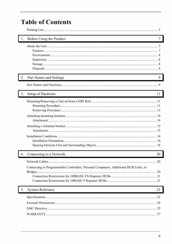
Table of Contents
Packing List ......................................................................................................................................... 5
1. Before Using the Product 7
About the Unit ..................................................................................................................................... 7 Features ........................................................................................................................................ 7 Environment ................................................................................................................................. 8 Inspection ..................................................................................................................................... 8 Storage ......................................................................................................................................... 8 Disposal ........................................................................................................................................ 8
2. Part Names and Settings 9
Part Names and Functions ................................................................................................................... 9
3. Setup of Hardware 11
Mounting/Removing a Unit on/from a DIN Rail .............................................................................. 11 Mounting Procedure ................................................................................................................... 11 Removing Procedure .................................................................................................................. 12
Attaching mounting brackets ............................................................................................................ 14 Attachment ................................................................................................................................. 14
Attaching a retention bracket ............................................................................................................ 15 Attachment ................................................................................................................................. 15
Installation Conditions ...................................................................................................................... 16 Installation Orientation ............................................................................................................... 16 Spacing between Unit and Surrounding Objects ........................................................................ 18
4. Connecting to a Network 20
Network Cables ................................................................................................................................. 20
Connecting to Programmable Controllers, Personal Computers, Additional HUB Units, or Bridges .............................................................................................................................................. 20
Connection Restrictions for 100BASE-TX Repeater HUBs ...................................................... 21 Connection Restrictions for 10BASE-T Repeater HUBs ........................................................... 21
5. System Reference 22
Specifications .................................................................................................................................... 22
External Dimensions ......................................................................................................................... 24
EMC Directive .................................................................................................................................. 25
WARRANTY .................................................................................................................................... 27
1. Before Using the Product
7
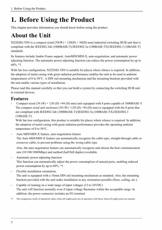
1. Before Using the Product This chapter provides information you should know before using the product.
About the Unit NZ2EHG-T8N is a compact-sized [39(W) × 120(D) × 94(H) mm] industrial switching HUB unit that is compliant with the IEEE802.3ab (1000BASE-T)/IEEE802.3u (100BASE-TX)/IEEE802.3 (10BASE-T) standards.
Its features include Jumbo Frame support, AutoMDI/MDI-X, auto-negotiation, and automatic power adjusting function. The automatic power adjusting function can reduce the power consumption by up to 60%. *1
With fan less configuration, NZ2EHG-T8N is suitable for places where silence is required. In addition, the adoption of metal casing with great radiation performance enables the unit to be used in ambient temperatures of 0 to 50°C. A DIN rail mounting mechanism and the mounting brackets provided with the unit enable various types of installation.
Please read this manual carefully so that you can build a system by connecting the switching HUB unit to external devices.
Features - Compact-sized (39 (W) × 120 (D) ×94 (H) mm) unit equipped with 8 ports capable of 1000BASE-T
The compact-sized unit enclosure (39 (W) ×120 (D) ×94 (H) mm) is equipped with the 8 ports that are compliant with IEEE802.3ab (1000BASE-T)/IEEE802.3u (100BASE-TX)/IEEE802.3 (10BASE-T). With fan less configuration, this product is suitable for places where silence is required. In addition, the adoption of metal casing with great radiation performance provides the operating ambient temperature of 0 to 50°C.
- Auto MDI/MDI-X feature, auto-negotiation feature The Auto MDI/MDI-X feature can automatically recognize the cable type, straight-through cable or crossover cable, to prevent problems using the wrong cable type.
Also, the auto-negotiation feature can automatically recognize and choose the best communication rate (10/100/1000Mbps) and method (half/full duplex) available.
- Automatic power adjusting function This function can automatically adjust the power consumption of unused ports, enabling reduced power consumption by up to 60%. *1
- Flexible installation orientation. The unit is equipped with a 35mm DIN rail mounting mechanism as standard. Also, the mounting brackets provided with the unit make installation in any orientation possible (floor, ceiling, etc.).
- Capable of running on a wide range of input voltages (12 to 24VDC) The unit will function normally even if input voltage fluctuates within the acceptable range. In addition, the power connector includes an FG terminal.
*1 The comparison result of measured values when all (eight) ports are in operation with those when all (eight) ports are unused.

1. Before Using the Product
8
Environment Use this product in the following environment. If used under environmental conditions exceeding these ranges, the board may overheat, malfunction, or cause a failure.
Operating temperature
0 to 50C
Operating humidity
10 to 90%RH (No condensation)
Corrosive gases
None
Floating dust particles
Small amounts (Non excessive)
Inspection
Inspect the product periodically as follows to use it safely.
Storage When storing this product, keep it in its original packing form.
(1) Put the unit in the storage bag.
(2) Wrap it in the packing material, then put it in the box.
(3) Store the package at room temperature at a place free from direct sunlight, moisture, shock, vibration, magnetism, and static electricity.
Disposal When disposing of the product, follow the disposal procedures stipulated under the relevant laws and municipal ordinances.
1
3
5
7
2
4
6
8
ii-+
VV
POWER
FG( )
12-24VDC
NZ2EHG-T8N
nor alien substance is attached to the ventilation slits.- The ventilation slits are not covered, and neither dust

2. Part Names and Settings
9
2. Part Names and Settings
Part Names and Functions
Figure 2.1. Part names
Table 2.1. LED indicators Name Status Color Display
POWER LED POWER Green OFF : Power off ON : Power on LED:A 10Mbps Yellow OFF : No LINK 100Mbps Green ON : LINK LED:B 1000Mbps Green Flashing : ACT (Data send/receive)
Table 2.2. Connectors Name Function
Power connector Power terminal connector (included in the package): MC1,5/3-ST-3,5 (made by Phoenix Contact Inc.) The applicable cable is AWG28-16. (The cable length must meet the power supply specifications.) Secure the connector with a retention bracket. Connect the power cable to the power terminal connector by screw connection. The fastening torque range is 0.22 to 0.25Nm. Power connector MC1,5/3-G-3,5 (Phoenix Contact)
Pin number Signal Description
1 Vi+ Power (12-24VDC5%)
2 Vi- Power (GND)
3 FG Frame Grand
Power supply
10BASE-T/100BASE-TX/
1000BASE- T port
POWER LED
LED : A
LED : B
LED : A
LED : B1
3
5
7
2
4
6
8
ii-+
VV
POWER
(FG)
12-24VDC
NZ2EHG-T8N
connector
Vi+
Vi-
FG
12-24VDC

2. Part Names and Settings
10
Table 2.3. 10BASE-T/100BASE-TX/1000BASE-T port Name Function
10BASE-T/ 100BASE-TX/ 1000BASE-T port
Ports 1 to 8 Use these ports to connect personal computers, additional HUB units, bridges, or other devices. Communication rate (10/100/1000Mbps) and communication method (half/full duplex) can be automatically recognized. Using the Auto MDI/MDI-X function, the cable type (straight-through or crossover cable) can be automatically recognized.
Used connector JC0-0182NL (Pulse)
Pin name Signal Description
1 TRD+ (0) Data0 transmit and receive (+) 2 TRD- (0) Data0 transmit and receive (-) 3 TRD+ (1) Data1 transmit and receive (+) 4 TRD+ (2) Data2 transmit and receive (+) 5 TRD- (2) Data2 transmit and receive (-) 6 TRD- (1) Data1 transmit and receive (-) 7 TRD+ (3) Data3 transmit and receive (+) 8 TRD- (3) Data3 transmit and receive (-)
Power Supply
First, power on this module.
If there is much noise, install a noise filter on power cables.
Use a power supply capable of establishing 11.6VDC or higher within 50ms. Power supplies that can not meet this requirement may cause device failures or accidents.
Figure 2.2. Time required to establish certain voltage
1
8
Time (ms)
Input voltage (V)
25.2
24
12
11.6
50
3. Setup of Hardware
11
3. Setup of Hardware
Mounting/Removing a Unit on/from a DIN Rail
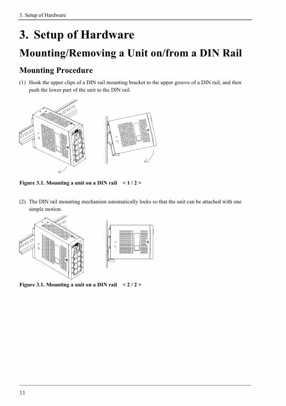
Mounting Procedure (1) Hook the upper clips of a DIN rail mounting bracket to the upper groove of a DIN rail, and then
push the lower part of the unit to the DIN rail.
Figure 3.1. Mounting a unit on a DIN rail < 1 / 2 >
(2) The DIN rail mounting mechanism automatically locks so that the unit can be attached with one simple motion.
Figure 3.1. Mounting a unit on a DIN rail < 2 / 2 >
8
6
4
2
7
5
3
1i
i-+
V
V
FG( )
POWER
12-24V
DC
NZ2EHG-T8N
8
6
4
2
7
5
3
1
i
i-
+
V
V
FG( )
POWER
12-24V
DC
NZ2EHG-T8N
3. Setup of Hardware
12
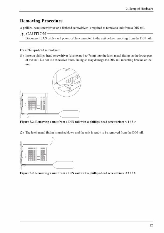
Removing Procedure A phillips-head screwdriver or a flathead screwdriver is required to remove a unit from a DIN rail.
Disconnect LAN cables and power cables connected to the unit before removing from the DIN rail.
For a Phillips-head screwdriver
(1) Insert a phillips-head screwdriver (diameter: 6 to 7mm) into the latch metal fitting on the lower part of the unit. Do not use excessive force. Doing so may damage the DIN rail mounting bracket or the unit.
Figure 3.2. Removing a unit from a DIN rail with a phillips-head screwdriver < 1 / 3 >
(2) The latch metal fitting is pushed down and the unit is ready to be removed from the DIN rail.
Figure 3.2. Removing a unit from a DIN rail with a phillips-head screwdriver < 2 / 3 >
CAUTION

3. Setup of Hardware
13
(3) By lifting the unit, you can easily remove it from the DIN rail.
Figure 3.2. Removing a unit from a DIN rail with a phillips-head screwdriver < 3 / 3 >
For a flathead screwdriver
(1) Insert a flathead screwdriver (tooth width 5.5 to 7mm) into the latch metal fitting on the lower part of the unit, and push the tip of the screwdriver down vertically.
Do not use excessive force. Doing so may damage the DIN rail mounting bracket or the unit.
Figure 3.3. Removing a unit from a DIN rail with a flathead screwdriver < 1 / 3 >
(2) The latch metal fitting is pushed down and the unit is ready to be removed from the DIN rail.
Figure 3.3. Removing a unit from a DIN rail with a flathead screwdriver < 2 / 3 >

3. Setup of Hardware
14
(3) By lifting the unit, you can easily remove it from the DIN rail.
Figure 3.3. Removing a unit from a DIN rail with a flathead screwdriver < 3 / 3 >
Attaching mounting brackets
Attachment Remove the four screws and separate the DIN rail mounting bracket from the unit.
Figure 3.4. Separating the DIN rail mounting bracket
Mounting brackets
Attach mounting brackets to the unit using bracket screws.
Figure 3.5. Attaching mounting brackets
8
6
4
2
7
5
3
1
ii-+
VV
FG
( )
POW
ER
12-24VDC
NZ2E
HG-T
8N

3. Setup of Hardware
15
Attaching a retention bracket
Attachment (1) Plug in the power terminal connector to the power connector and attach the retention bracket using
a bracket screw.
Figure 3.6. Attaching a retention bracket
8
6
4
2
7
5
3
1
i
i
-
+
V
V
FG( )
POWER
12-24VDC
NZ2EHG-T8N8
6
4
2
7
5
3
1
i
i
-
+
V
V
FG( )
POWER
12-24VDC
NZ2EHG-T8N

3. Setup of Hardware
16
Installation Conditions
When used in applications with high environmental temperatures, even if the unit is operated within the temperature range specification, make sure that heat generated by the unit has an adequate dissipation path.
Installation Orientation
When a DIN rail mounting bracket is used
Avoid installation in an unsuitable installation orientation as insufficient heat dissipation may occur.
Figure 3.7. Installation orientation (with a DIN rail mounting bracket)
CAUTION

3. Setup of Hardware
17
When mounting brackets are used
Installation in any orientation is possible.
Figure 3.8. Installation orientations (with mounting brackets)

3. Setup of Hardware
18
Spacing between Unit and Surrounding Objects
Do not install the unit in a sealed housing.
When installed using a DIN rail mounting bracket
Ensure the distance between the unit and any surrounding objects as follows: Above and below the unit: 50mm or more Sides of the unit: 50mm or more (At least 5.8mm on the rating plate side).
Figure 3.9. Spacing between the unit and any surrounding objects when installed using a
DIN rail mounting bracket
CAUTION

3. Setup of Hardware
19
When installed using mounting brackets
Ensure the distance between the unit and any surrounding objects as follows: Above and below the unit: 50mm or more Under the rating plate side of the unit: 5.8mm or more On each side of the unit: 50mm or more
Figure 3.10. Spacing between the unit and any surrounding objects when installed using mounting brackets

4. Connecting to a Network
20
4. Connecting to a Network
Network Cables Cables meeting the following specifications should be used:
- 10BASE-T : Category 3 or higher UTP, STP cable 100m or less
- 100BASE-TX : Category 5 or higher UPT, STP cable 100m or less
- 1000BASE-T : Category 5e or higher UTP, STP cable 100m or less
- There are two types for UTP and STP cables: a straight-through cable and a crossover cable. The Auto MDI/MDI-X feature allows connections using either type of a cable.
Connecting to Programmable Controllers, Personal Computers, Additional HUB Units, or Bridges When connecting a programmable controller, personal computer, additional HUB unit, bridge, or other device, connect it to any 10BASE-T/100BASE-TX/1000BASE-T port of the switching HUB unit using either a straight-through or crossover cable.
To use Jumbo Frame, it is necessary for other network devices of the communication target, such as
LAN adapters, to be Jumbo Frame compatible.
Figure 4.1. Connection example
CAUTION
NZ2EHG-T8N Q06UDEHCPU .,etc
Straight or cross cables

4. Connecting to a Network
21
Connection Restrictions for 100BASE-TX Repeater HUBs Using Class I 100BASE-TX repeater HUBs, cascade connections are not possible. Up to two stages of cascade connections are possible with Class II 100BASE-TX repeater HUBs. In addition, the maximum total length of cables (1) (2) (3) is 205m or less. For details, refer to the user's manual for the 100BASE-TX repeater HUB used.
Figure 4.2. Connection restrictions for 100BASE-TX repeater HUBs (Class II)
Connection Restrictions for 10BASE-T Repeater HUBs As many as four stages of 10BASE-T repeater HUBs can be connected using cascade connection. In addition, the length of UTP or STP cable between cascaded HUBs is 100m or less. For details, refer to the user's manual for the 10BASE-T repeater HUB used.
Figure 4.3. Connection restrictions for 10BASE-T repeater HUBs
NZ2EHG-T8N
(1) (2)
- Use UTP and STP cables with category 5 or higher for cables (1)(2)(3).
100BASE-TX HUB(Class II)
(3)- The total length of cables (1)(2)(3) should be set to 205m or less.
100BASE-TX HUB(Class II)
- The length of cable (2) should be 5m or less.
NZ2EHG-T8N 10BASE-T HUB

5. System Reference
22
5. System Reference
Specifications
Table 5.1. Specifications
Item Specifications
Ethernet standards IEEE802.3/IEEE802.3u /IEEE802.3ab –compliant
Data communication rate 10/100/1000Mbps (auto-recognition)
Access method CSMA/CD
Communication method All ports: Full/Half duplex (auto-recognition)
Topology Star topology
Flow control Full Duplex : IEEE802.3x compliant flow control
Half Duplex :Back pressure
Number of effective ports 8
Switching method Store and forward
Address table 8,192 entries
Jumbo frame*1 9.6Kbyte
Buffer capacity 512Kbyte
Aging time 300s (Max.)
LED indicator POWER (Green), LINK/ACT 10M (Yellow), LINK/ACT 100M (Green), LINK/ACT 1000M (Green)
Power supply voltage 12V - 24VDC5%
FG terminal The power connector is equipped with FG terminal.
Power consumption (Max.) 0.65A at 12VDC, 0.35A at 24VDC
Physical dimensions (mm) 39 (W) x 120 (D) x 94 (H) (excluding protrusions)
Weight 360g (410g with a DIN rail mounting bracket or two mounting brackets)
Installation method Onto a DIN rail or on the wall
*1 To use Jumbo Frame, it is necessary for other network devices on the communication route to be Jumbo Frame compatible.

5. System Reference
23
Table 5.2. Installation environment requirements
Item Specification
Operating ambient temperature 0 to 50C
Storage ambient temperature -10 to 60C
Ambient humidity 10 to 90%RH (No condensation)
Floating dust particles Tolerant of small amounts (non excessive)
Corrosive gases None
Noise immunity
Line-noise AC line/2kV, Signal line/1kV (JIS C61000-4-4 Level 3, IEC61000-4-4 Level 3)
Electrostatic discharge immunity
Contact discharge/4kV (JIS C61000-4-2 Level 2, IEC61000-4-2 Level 2) Air discharge/8kV (JIS C61000-4-2 Level 3, IEC61000-4-2 Level 3)
Vibration
resistance Sweep resistance
10 to 57Hz/ half amplitude 0.15mm,57 to 150Hz/2.0G 40minutes each in X, Y, and Z directions
(JIS C60068-2-6-compliant, IEC60068-2-6-compliant)
Shock resistance 15G, sine half-wave pulse for 11ms each in X, Y, and Z directions
(JIS C60068-2-27-compliant, IEC60068-2-27-compliant)
Grounding Ground the FG terminal to the protective ground conductor.
Installation location Inside a control panel

5. System Reference
24
External Dimensions
Figure 5.1. External dimensions with a DIN rail mounting bracket (standard)
Figure 5.2. External dimensions with mounting brackets

5. System Reference
25
EMC Directive Compliance with the EMC Directive, which is one of the EU directives, has been mandatory for the products sold within EU member states since 1996.
To prove the compliance with the EMC Directive, manufactures must issue an EC Declaration of Conformity and the products must bear a CE marking.
This product is compliant to with EN55022, EN55024, and EN61000-6-2.
(1) Authorized representative in EU member states
The authorized representative in EU member states will be:
Company name : Mitsubishi Electric Europe BV
Address : Gothaer strasse 8, 40880 Ratingen, Germany

26
MEMO

27
WARRANTY Please confirm the following product warranty details before using this product.
1. Gratis Warranty Term and Gratis Warranty Range
If any faults or defects (hereinafter "Failure") found to be the responsibility of Mitsubishi occurs during use of the product within the gratis warranty term, the product shall be repaired at no cost via the sales representative or Mitsubishi Service Company.
However, if repairs are required onsite at domestic or overseas location, expenses to send an engineer will be solely at the customer’s discretion. Mitsubishi shall not be held responsible for any re-commissioning, maintenance, or testing on-site that involves replacement of the failed module.
[Gratis Warranty Term]
The gratis warranty term of the product shall be for one year after the date of purchase or delivery to a designated place.
Note that after manufacture and shipment from Mitsubishi, the maximum distribution period shall be six (6) months, and the longest gratis warranty term after manufacturing shall be eighteen (18) months. The gratis warranty term of repair parts shall not exceed the gratis warranty term before repairs.
[Gratis Warranty Range]
(1) The range shall be limited to normal use within the usage state, usage methods and usage environment, etc., which follow the conditions and precautions, etc., given in the instruction manual, user's manual and caution labels on the product.
(2) Even within the gratis warranty term, repairs shall be charged for in the following cases.
1. Failure occurring from inappropriate storage or handling, carelessness or negligence by the user. Failure caused by the user's hardware or software design.
2. Failure caused by unapproved modifications, etc., to the product by the user.
3. When the Mitsubishi product is assembled into a user's device, Failure that could have been avoided if functions or structures, judged as necessary in the legal safety measures the user's device is subject to or as necessary by industry standards, had been provided.
4. Failure that could have been avoided if consumable parts (battery, backlight, fuse, etc.) designated in the instruction manual had been correctly serviced or replaced.
5. Failure caused by external irresistible forces such as fires or abnormal voltages, and Failure caused by force majeure such as earthquakes, lightning, wind and water damage.
6. Failure caused by reasons unpredictable by scientific technology standards at time of shipment from Mitsubishi.
7. Any other failure found not to be the responsibility of Mitsubishi or that admitted not to be so by the user.

28
2. Onerous repair term after discontinuation of production
(1) Mitsubishi shall accept onerous product repairs for six (6) years after production of the product is discontinued.
Discontinuation of production shall be notified with Mitsubishi Technical Bulletins, etc.
(2) Product supply (including repair parts) is not available after production is discontinued.
3. Overseas service
Overseas, repairs shall be accepted by Mitsubishi's local overseas FA Center. Note that the repair conditions at each FA Center may differ.
4. Exclusion of loss in opportunity and secondary loss from warranty
liability
Regardless of the gratis warranty term, Mitsubishi shall not be liable for compensation to:
(1) Damages caused by any cause found not to be the responsibility of Mitsubishi.
(2) Loss in opportunity, lost profits incurred to the user by Failures of Mitsubishi products.
(3) Special damages and secondary damages whether foreseeable or not, compensation for accidents, and compensation for damages to products other than Mitsubishi products.
(4) Replacement by the user, maintenance of on-site equipment, start-up test run and other tasks.
5. Changes in product specifications
The specifications given in the catalogs, manuals or technical documents are subject to change without prior notice.
Major differences in after-sales service compared to MELSEC iQ-R/Q/L Series, and others
(1) The gratis warranty term of the product shall be for one (1) year after the date of delivery or for eighteen (18) months after manufacturing, whichever is less.
(2) The onerous repair term after discontinuation of production shall be for six (6) years. (3) Mitsubishi shall mainly replace products that need repair. (4) It may take some time to respond to the problem or repair the product depending on the condition
and timing.
29
Revisions *The manual number is given on the bottom right of the cover.
Print Date *Manual Number Revision
January 2016 IB(NA)-0800554-A First edition