100Gbps CFP4 SR4 Optical Transceiver Module …€¦ · Optech Technology Co., Ltd. Version: 16V.A...
16
Optech Technology Co., Ltd. 2F., No.41, Ln. 221, Gangqian Rd., Neihu Dist., Taipei City 114, Taiwan, R.O.C. Tel: +886-2-2656-0588 Fax: +886-2-2656-0599 http://www.optech.com.tw e-mail: [email protected] Version: 16V.A Page 1 of 16 100Gbps CFP4 SR4 Optical Transceiver Module OPHW-MX1-85-CB datasheet Features Hot pluggable CFP4 MSA form factor Compliant to IEEE 802.3bm 100GBASE-SR4 Supports 103.1Gb/s aggregate bit rate Up to 100m OM4 MMF transmission Single +3.3V power supply Operating case temperature: 0 to 70℃ 4x25G electrical interface (CEI-28G-VSR) MDIO management interface with digital diagnostic monitoring Maximum power consumption 3.5W MTP/MPO optical connector RoHS-6 compliant Applications 100GBASE-SR4 Ethernet Absolute Maximum Ratings Notes: 1. PIN receiver. Parameter Symbol Min. Max. Units Note Storage Temperature Ts -40 85 ℃ Relative Humidity (non-condensation) RH 0 85 % Operating Case Temperature Top 0 70 ℃ Supply Voltage Vcc -0.5 3.6 V Voltage on LVTTL Input Vilvttl -0.5 VCC3+0.3 V LVTTL Output Current Iolvttl 15 mA Voltage on Open Collector Output Voco 0 6 V Damage Threshold, each Lane THd 3.4 dBm 1
-
Upload
phungkhanh -
Category
Documents
-
view
220 -
download
0
Transcript of 100Gbps CFP4 SR4 Optical Transceiver Module …€¦ · Optech Technology Co., Ltd. Version: 16V.A...

Optech Technology Co., Ltd.
2F., No.41, Ln. 221, Gangqian Rd., Neihu Dist., Taipei City 114, Taiwan, R.O.C. Tel: +886-2-2656-0588 Fax: +886-2-2656-0599 http://www.optech.com.tw e-mail: [email protected]
Version: 16V.A Page 1 of 16
100Gbps CFP4 SR4 Optical Transceiver Module
OPHW-MX1-85-CB datasheet
Features
Hot pluggable CFP4 MSA form factor
Compliant to IEEE 802.3bm 100GBASE-SR4
Supports 103.1Gb/s aggregate bit rate
Up to 100m OM4 MMF transmission
Single +3.3V power supply
Operating case temperature: 0 to 70℃
4x25G electrical interface (CEI-28G-VSR)
MDIO management interface with digital
diagnostic monitoring
Maximum power consumption 3.5W
MTP/MPO optical connector
RoHS-6 compliant
Applications
100GBASE-SR4 Ethernet
Absolute Maximum Ratings
Notes:
1. PIN receiver.
Parameter Symbol Min. Max. Units Note
Storage Temperature Ts -40 85 ℃
Relative Humidity (non-condensation) RH 0 85 %
Operating Case Temperature Top 0 70 ℃
Supply Voltage Vcc -0.5 3.6 V
Voltage on LVTTL Input Vilvttl -0.5 VCC3+0.3 V
LVTTL Output Current Iolvttl 15 mA
Voltage on Open Collector Output Voco 0 6 V
Damage Threshold, each Lane THd 3.4 dBm 1

Optech Technology Co., Ltd.
2F., No.41, Ln. 221, Gangqian Rd., Neihu Dist., Taipei City 114, Taiwan, R.O.C. Tel: +886-2-2656-0588 Fax: +886-2-2656-0599 http://www.optech.com.tw e-mail: [email protected]
Version: 16V.A Page 2 of 16
100Gbps CFP4 SR4 Optical Transceiver Module
OPHW-MX1-85-CB datasheet
Recommended Operating Conditions
Diagnostics Monitoring
Parameter Symbol Accuracy Unit Notes
Temperature monitor absolute error DMI_Temp ± 3 C
Over operating
temperature range
Supply voltage monitor absolute error DMI_VCC ± 0.15 V Over full operating range
Channel RX power monitor absolute error DMI_RX_Ch ± 2 dB 1
Channel Bias current monitor
DMI_Ibias_Ch ± 10% mA Ch1~Ch4
Channel TX power monitor absolute error
DMI_TX_Ch ± 2 dB 1
Notes:
1. Due to measurement accuracy of different single mode fibers, there could be an additional +/-1 dB fluctuation,
or a +/- 3 dB total accuracy.
Parameter Symbol Min. Typ. Max. Units Note
Operating Case Temperature Top 0 70 ℃
Power Supply Voltage Vcc 3.135 3.3 3.465 V
Data Rate, each Lane 25.78125 Gb/s
Data Rate Accuracy -100 100 ppm
Control Input Voltage High 2 Vcc V
Control Input Voltage Low 0 0.8 V
Power Supply Noise Vrip
2 % DC-1MHz
3 % 1-10MHz
Link Distance (OM3 MMF) D1 70 m
Link Distance (OM4 MMF) D2 100 m

Optech Technology Co., Ltd.
2F., No.41, Ln. 221, Gangqian Rd., Neihu Dist., Taipei City 114, Taiwan, R.O.C. Tel: +886-2-2656-0588 Fax: +886-2-2656-0599 http://www.optech.com.tw e-mail: [email protected]
Version: 16V.A Page 3 of 16
100Gbps CFP4 SR4 Optical Transceiver Module
OPHW-MX1-85-CB datasheet
Transmitter Electro-Optical Characteristics (each Lane)
Parameter Test Point Min Typ. Max Units Notes
Power Consumption 3.5 W
Supply Current Icc 1.06 A
Low Power Mode Power Dissipation 1.0 W
Overload Differential Voltage pk-pk TP1a 900 mV
Common Mode Voltage (Vcm) TP1 -350 2850 mV 1
Differential Termination Resistance
Mismatch TP1 10 % At 1MHz
Differential Return Loss (SDD11) TP1
See CEI-
28G-VSR
Equation
13-19
dB
Common Mode to Differential
conversion and Differential to
Common Mode conversion
(SDC11, SCD11)
TP1
See CEI-
28G-VSR
Equation
13-20
dB
Stressed Input Test TP1a
See CEI-
28G-VSR
Section
13.3.11.2.1
Center Wavelength λc 840 850 860 nm
RMS Spectral Width △λrms 0.6 nm
Average Launch Power, each Lane PAVG -8.4 2.4 dBm
Optical Modulation Amplitude (OMA),
each Lane POMA -6.4 3.0 dBm 2
Launch Power in OMA minus TDEC,
each Lane -7.3 dBm
Transmitter and Dispersion Eye
Closure (TDEC), each Lane 4.3 dB
Extinction Ratio ER 2.0 dB
Optical Return Loss Tolerance TOL 12 dB
Average Launch Power OFF
Transmitter, each Lane Poff -30 dBm
Encircled Flux ≧86% at 19μm
≦30% at 4.5μm
Optech Technology Co., Ltd.
2F., No.41, Ln. 221, Gangqian Rd., Neihu Dist., Taipei City 114, Taiwan, R.O.C. Tel: +886-2-2656-0588 Fax: +886-2-2656-0599 http://www.optech.com.tw e-mail: [email protected]
Version: 16V.A Page 4 of 16
100Gbps CFP4 SR4 Optical Transceiver Module
OPHW-MX1-85-CB datasheet
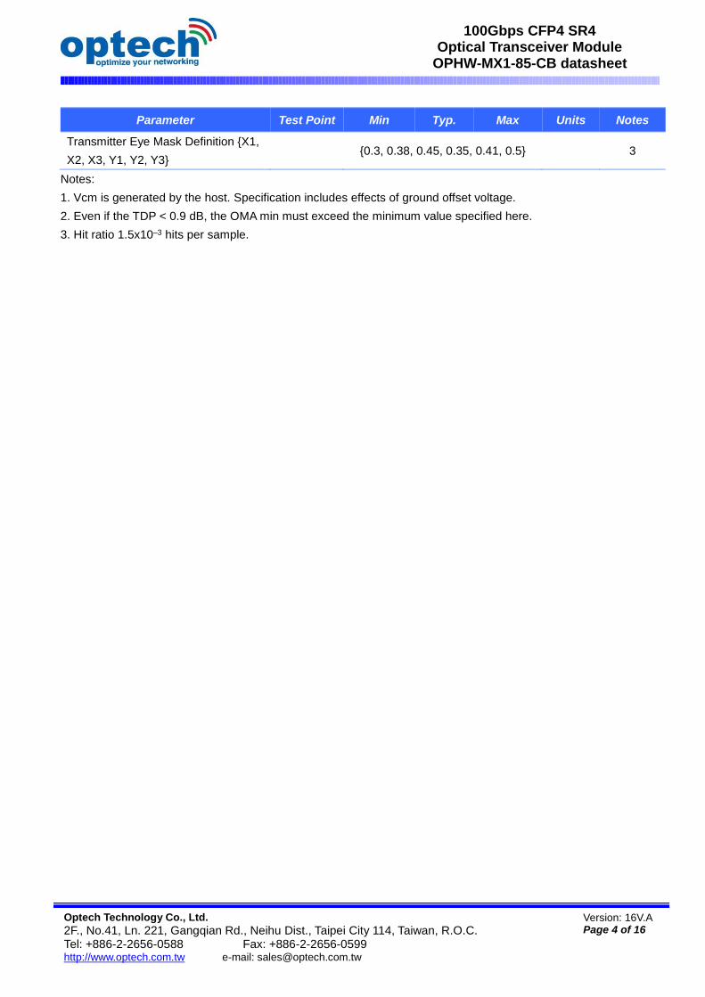
Parameter Test Point Min Typ. Max Units Notes
Transmitter Eye Mask Definition {X1,
X2, X3, Y1, Y2, Y3} {0.3, 0.38, 0.45, 0.35, 0.41, 0.5} 3
Notes:
1. Vcm is generated by the host. Specification includes effects of ground offset voltage.
2. Even if the TDP < 0.9 dB, the OMA min must exceed the minimum value specified here.
3. Hit ratio 1.5x10⁻³ hits per sample.

Optech Technology Co., Ltd.
2F., No.41, Ln. 221, Gangqian Rd., Neihu Dist., Taipei City 114, Taiwan, R.O.C. Tel: +886-2-2656-0588 Fax: +886-2-2656-0599 http://www.optech.com.tw e-mail: [email protected]
Version: 16V.A Page 5 of 16
100Gbps CFP4 SR4 Optical Transceiver Module
OPHW-MX1-85-CB datasheet
Receiver Electro-Optical Characteristics (each Lane)
Parameter Test Point Min Typ. Max Units Notes
Differential Voltage, pk-pk TP4 900 mV
Common Mode Voltage (Vcm) TP4 -350 2850 mV 1
Common Mode Noise, RMS TP4 17.5 mV
Differential Termination Resistance
Mismatch TP4 10 % At 1MHz
Differential Return Loss (SDD22) TP4
See CEI-
28G-VSR
Equation
13-19
dB
Common Mode to Differential
conversion and Differential to
Common Mode conversion
(SDC22, SCD22)
TP4
See CEI-
28G-VSR
Equation
13-21
dB
Common Mode Return Loss
(SCC22) TP4 -2 dB 2
Transition Time, 20 to 80% TP4 9.5 ps
Vertical Eye Closure (VEC) TP4 5.5 dB
Eye Width at 10-15 probability
(EW15) TP4 0.57 UI
Eye Height at 10-15 probability
(EH15) TP4 228 mV
Center Wavelength λc 840 850 860 nm
Damage Threshold, each Lane THd 3.4 dBm 3
Average Receive Power, each
Lane -10.3 2.4 dBm
Receive Power (OMA), each Lane 3.0 dBm
Receiver Sensitivity (OMA), each
Lane SEN -9.2 dBm
For
BER=5x10⁻⁵
Stressed Receiver Sensitivity
(OMA), each Lane -5.2 dBm 4
Receiver Reflectance RR -12 dB
LOS Assert LOSA -30 dBm
LOS Deassert LOSD -12 dBm
LOS Hysteresis LOSH 0.5 dB

Optech Technology Co., Ltd.
2F., No.41, Ln. 221, Gangqian Rd., Neihu Dist., Taipei City 114, Taiwan, R.O.C. Tel: +886-2-2656-0588 Fax: +886-2-2656-0599 http://www.optech.com.tw e-mail: [email protected]
Version: 16V.A Page 6 of 16
100Gbps CFP4 SR4 Optical Transceiver Module
OPHW-MX1-85-CB datasheet
Conditions of Stress Receiver Sensitivity Test (Note 5)
Stressed Eye Closure (SEC), Lane
under Test 4.3 dB
Stressed Eye J2 Jitter, Lane under
Test 0.39 UI
Stressed Eye J4 Jitter, Lane under
Test 0.53 UI
OMA of each Aggressor Lane 3 dBm
Stressed Receiver Eye Mask
Definition {X1, X2, X3, Y1, Y2, Y3},
Hit ratio 5x10⁻⁵ hits per sample
{0.28, 0.5, 0.5, 0.33, 0.33, 0.4}
Notes:
1. Vcm is generated by the host. Specification includes effects of ground offset voltage.
2. From 250MHz to 30GHz.
3. The receiver shall be able to tolerate, without damage, continuous exposure to a modulated optical input signal
having this power level on one lane. The receiver does not have to operate correctly at this input power.
4. Measured with conformance test signal at receiver input for BER = 5x10⁻⁵
5. Vertical eye closure penalty, stressed eye J2 jitter, stressed eye J4 jitter, and stressed receiver eye mask
definition are test conditions for measuring stressed receiver sensitivity. They are not characteristics of the
receiver.

Optech Technology Co., Ltd.
2F., No.41, Ln. 221, Gangqian Rd., Neihu Dist., Taipei City 114, Taiwan, R.O.C. Tel: +886-2-2656-0588 Fax: +886-2-2656-0599 http://www.optech.com.tw e-mail: [email protected]
Version: 16V.A Page 7 of 16
100Gbps CFP4 SR4 Optical Transceiver Module
OPHW-MX1-85-CB datasheet
Block Diagram of Transceiver
This product is a 100Gb/s transceiver module for optical communication applications compliant to 100GBASE-
SR4 of the IEEE P802.3bm standard. The module converts 4 input channels of 25Gb/s electrical data to 4
channels of VCSEL optical signals over 4 multimode fibers for 100Gb/s optical transmission. Reversely, on the
receiver side, the module receives 4 channels of VCSEL optical signals over 4 multimode fibers and then
converts them to 4 output channels of 25Gb/s electrical data.
The high speed VCSEL transmitters and high sensitivity PIN receivers provide superior performance for
100Gigabit Ethernet applications up to 100m links over OM4 multimode fibers and compliant to optical interface
with IEEE802.3bm Clause 95 100GBASE-SR4 requirements.
The product is designed with form factor, optical/electrical connection and MDIO interface according to the CFP4
Multi-Source Agreement (MSA). The innovative design has all the fibers inside the CFP4 package configured
without any splicing or non-permanent connector. Also, fiber routines are neatly organized and fixed inside a
stainless steel container.
This product contains an MTP/MPO optical connector for the optical interface and a 56-pin connector for the
electrical interface. Figure 1 in Section 3 shows the functional block diagram of this product.
Transmitter Operation
The transceiver module receives 4 channels of 25Gb/s electrical data, which are processed by a 4-channel Clock
and Data Recovery (CDR) IC that reshapes and reduces the jitter of each electrical signal. Subsequently, each of
4 EML laser driver IC's converts one of the 4 channels of electrical signals to an optical signal that is transmitted
from one of the 4 VCSEL lasers which are packaged in the Transmitter Optical Sub-Assembly (TOSA). Each
laser launches an optical signal whose characteristics are compliant to IEEE802.3bm 100GBASE-SR4
requirements. The optical output power of each channel is maintained constant by an automatic power control
(APC) circuit. The transmitter output can be turned off by TX_DIS hardware signal and/or through MDIO module
management interface.
Optech Technology Co., Ltd.
2F., No.41, Ln. 221, Gangqian Rd., Neihu Dist., Taipei City 114, Taiwan, R.O.C. Tel: +886-2-2656-0588 Fax: +886-2-2656-0599 http://www.optech.com.tw e-mail: [email protected]
Version: 16V.A Page 8 of 16
100Gbps CFP4 SR4 Optical Transceiver Module
OPHW-MX1-85-CB datasheet
Receiver Operation
The receiver receives 4 channels of VCSEL optical signals over 4 multimode fibers and each of the 4 channels of
optical signals is fed into one of the 4 receivers that are packaged into the Receiver Optical Sub-Assembly
(ROSA). Each receiver converts the optical signal to an electrical signal. The regenerated electrical signals are
retimed and de-jittered and amplified by the RX portion of the 4-channel CDR. The retimed 4-lane output
electrical signals are compliant with IEEE CAUI-4 interface requirements. In addition, each received optical signal
is monitored by the DOM section. The monitored value is reported through the MDIO section. If one or more
received optical signal is weaker than the threshold level, RX_LOS hardware alarm will be triggered.
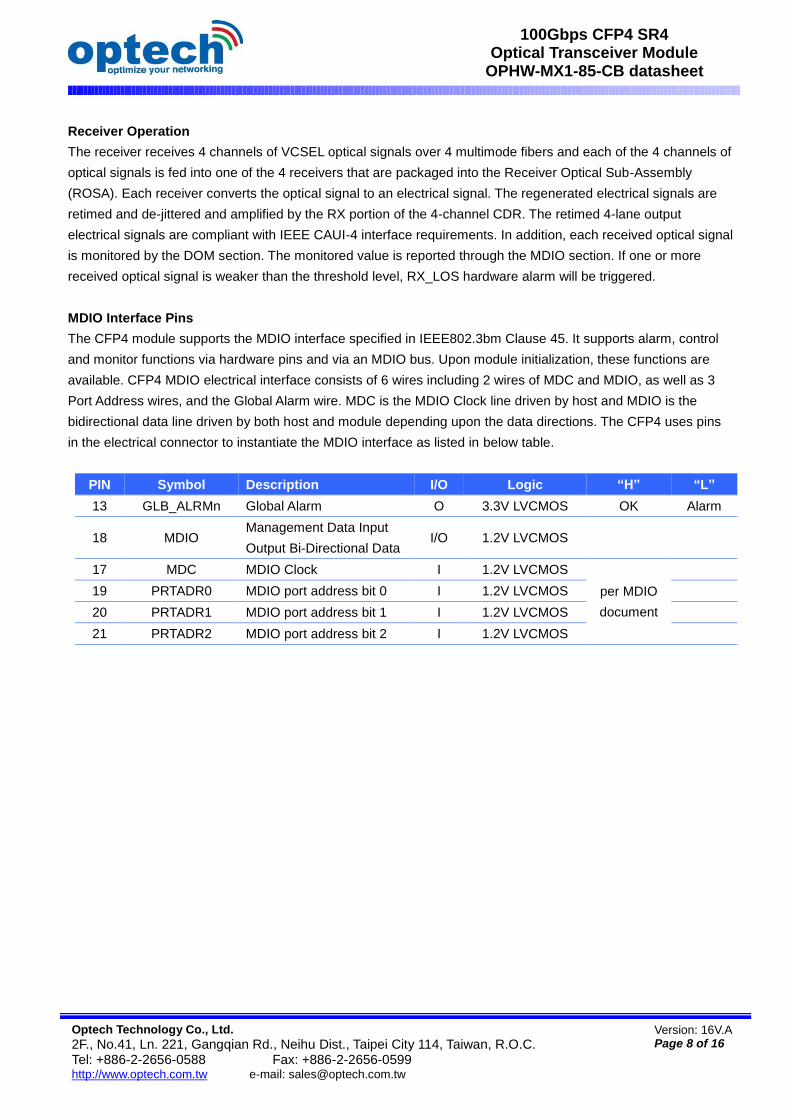
MDIO Interface Pins
The CFP4 module supports the MDIO interface specified in IEEE802.3bm Clause 45. It supports alarm, control
and monitor functions via hardware pins and via an MDIO bus. Upon module initialization, these functions are
available. CFP4 MDIO electrical interface consists of 6 wires including 2 wires of MDC and MDIO, as well as 3
Port Address wires, and the Global Alarm wire. MDC is the MDIO Clock line driven by host and MDIO is the
bidirectional data line driven by both host and module depending upon the data directions. The CFP4 uses pins
in the electrical connector to instantiate the MDIO interface as listed in below table.
PIN Symbol Description I/O Logic “H” “L”
13 GLB_ALRMn Global Alarm O 3.3V LVCMOS OK Alarm
18 MDIO Management Data Input
Output Bi-Directional Data I/O 1.2V LVCMOS
17 MDC MDIO Clock I 1.2V LVCMOS
per MDIO
document
19 PRTADR0 MDIO port address bit 0 I 1.2V LVCMOS
20 PRTADR1 MDIO port address bit 1 I 1.2V LVCMOS
21 PRTADR2 MDIO port address bit 2 I 1.2V LVCMOS

Optech Technology Co., Ltd.
2F., No.41, Ln. 221, Gangqian Rd., Neihu Dist., Taipei City 114, Taiwan, R.O.C. Tel: +886-2-2656-0588 Fax: +886-2-2656-0599 http://www.optech.com.tw e-mail: [email protected]
Version: 16V.A Page 9 of 16
100Gbps CFP4 SR4 Optical Transceiver Module
OPHW-MX1-85-CB datasheet
Pin Orientation

Optech Technology Co., Ltd.
2F., No.41, Ln. 221, Gangqian Rd., Neihu Dist., Taipei City 114, Taiwan, R.O.C. Tel: +886-2-2656-0588 Fax: +886-2-2656-0599 http://www.optech.com.tw e-mail: [email protected]
Version: 16V.A Page 10 of 16
100Gbps CFP4 SR4 Optical Transceiver Module
OPHW-MX1-85-CB datasheet
Pin Map

Optech Technology Co., Ltd.
2F., No.41, Ln. 221, Gangqian Rd., Neihu Dist., Taipei City 114, Taiwan, R.O.C. Tel: +886-2-2656-0588 Fax: +886-2-2656-0599 http://www.optech.com.tw e-mail: [email protected]
Version: 16V.A Page 11 of 16
100Gbps CFP4 SR4 Optical Transceiver Module
OPHW-MX1-85-CB datasheet
Definition of the Bottom Side Pins from Pin 1 through Pin 28
PIN Name I/O Logic Description
1 3.3V_GND 3.3V Module Supply Voltage Return Ground, can be separated
or tied together with Signal Ground
2 3.3V_GND
3 3.3V
4 3.3V
5 3.3V
6 3.3V 3.3V Module Supply Voltage
7 3.3V_GND
8 3.3V_GND
9 VIND_IO_A I/O Module Vendor I/O A. Do Not Connect
10 VIND_IO_B I/O Module Vendor I/O B. Do Not Connect
11 TX_DIS
(PRG_CNTL1) I
LVCMOS
w/PUR
Transmitter Disable for all lanes. "1" or NC: Transmitter
disabled; "0": transmitter enabled. (Optionally configurable as
Programmable Control1 after Reset)
12 RX_LOS
(PRG_ALRM1) O
LVCMOS
w/PUR
Receiver Loss of Optical Signal. "1": low optical signal; "0":
normal condition (Optionally configurable as Programmable
Alarm1 after Reset)
13 GLB_ALRMn O LVCMOS Global Alarm. "0": alarm condition in any MDIO Alarm register;
"1": no alarm condition, Open Drain, Pull up Resistor on Host
14 MOD_LOPWR I LVCMOS
w/PUR
Module Low Power Mode. "1" or NC: module in low power
(safe) mode; "0": power-on enabled
15 MOD_ABS O GND Module Absent. "1" or NC: module absent; "0": module
present, Pull up resistor on Host
16 MOD_RSTn I LVCMOS
w/PDR
Module Reset. "0": resets the module; "1" or NC: module
enabled, Pull down Resistor in Module
17 MDC I 1.2V CMOS Management Data Clock (electrical specs as per IEEE Std
802.3-2012)
18 MDIO I/O 1.2V CMOS Management Data I/O bi-directional data (electrical specs as
per IEEE Std 802.3ae-2008 and ba-2010)
19 PRTADR0 I 1.2V CMOS MDIO Physical Port address bit 0
20 PRTADR1 I 1.2V CMOS MDIO Physical Port address bit 1
21 PRTADR2 I 1.2V CMOS MDIO Physical Port address bit 2
22 VND_IO_C I/O Module Vendor I/O C. Do Not Connect
23 VND_IO_D I/O Module Vendor I/O D. Do Not Connect
24 VND_IO_E I/O Module Vendor I/O E. Do Not Connect
25 GND
26 (MCLKn) O CML For optical waveform testing. Not for normal use
27 (MCLKp) O CML For optical waveform testing. Not for normal use
28 GND

Optech Technology Co., Ltd.
2F., No.41, Ln. 221, Gangqian Rd., Neihu Dist., Taipei City 114, Taiwan, R.O.C. Tel: +886-2-2656-0588 Fax: +886-2-2656-0599 http://www.optech.com.tw e-mail: [email protected]
Version: 16V.A Page 12 of 16
100Gbps CFP4 SR4 Optical Transceiver Module
OPHW-MX1-85-CB datasheet
Definition of Top Side Pins
PIN Name PIN Name
29 GND 43 (REFCLKp)
30 RX0p 44 GND
31 RX0n 45 TX0p
32 GND 46 TX0n
33 RX1p 47 GND
34 RX1n 48 TX1p
35 GND 49 TX1n
36 RX2p 50 GND
37 RX2n 51 TX2p
38 GND 52 TX2n
39 RX3p 53 GND
40 RX3n 54 TX3p
41 GND 55 TX3n
42 (REFCLKn) 56 GND

Optech Technology Co., Ltd.
2F., No.41, Ln. 221, Gangqian Rd., Neihu Dist., Taipei City 114, Taiwan, R.O.C. Tel: +886-2-2656-0588 Fax: +886-2-2656-0599 http://www.optech.com.tw e-mail: [email protected]
Version: 16V.A Page 13 of 16
100Gbps CFP4 SR4 Optical Transceiver Module
OPHW-MX1-85-CB datasheet
Optical Interface Lanes and Assignment
Figure below shows the orientation of the multi-mode fiber facets of the optical connector. Table below provides
the lane assignment.
Outside View of the CFP4 Module MPO Receptacle
Table: Lane assignment
Fiber # Lane Assignment
1 RX0
2 RX1
3 RX2
4 RX3
5 Not used
6 Not used
7 Not used
8 Not used
9 TX3
10 TX2
11 TX1
12 TX0

Optech Technology Co., Ltd.
2F., No.41, Ln. 221, Gangqian Rd., Neihu Dist., Taipei City 114, Taiwan, R.O.C. Tel: +886-2-2656-0588 Fax: +886-2-2656-0599 http://www.optech.com.tw e-mail: [email protected]
Version: 16V.A Page 14 of 16
100Gbps CFP4 SR4 Optical Transceiver Module
OPHW-MX1-85-CB datasheet
Dimensions

Optech Technology Co., Ltd.
2F., No.41, Ln. 221, Gangqian Rd., Neihu Dist., Taipei City 114, Taiwan, R.O.C. Tel: +886-2-2656-0588 Fax: +886-2-2656-0599 http://www.optech.com.tw e-mail: [email protected]
Version: 16V.A Page 15 of 16
100Gbps CFP4 SR4 Optical Transceiver Module
OPHW-MX1-85-CB datasheet
Optical Receptacle Cleaning Recommendations :
All fiber stubs inside the receptacle portions were cleaned before shipment. In the event of contamination
of the optical ports, the recommended cleaning process is the use of forced nitrogen. If contamination is
thought to have remained, the optical ports can be cleaned using a NTT international Cletop® stick type and
HFE7100 cleaning fluid. Before the mating of patch-cord, the fiber end should be cleaned up by using
Cletop® cleaning cassette.

Optech Technology Co., Ltd.
2F., No.41, Ln. 221, Gangqian Rd., Neihu Dist., Taipei City 114, Taiwan, R.O.C. Tel: +886-2-2656-0588 Fax: +886-2-2656-0599 http://www.optech.com.tw e-mail: [email protected]
Version: 16V.A Page 16 of 16
100Gbps CFP4 SR4 Optical Transceiver Module
OPHW-MX1-85-CB datasheet
Ordering Information
OP - - -
Model Number Part Number Voltage Temperature
CFP4-100G-SR4 OPHW-MX1-85-CB 3.3V 0C to 70 C
Note: All information contained in this document is subject to change without notice.
6 C S 10 13 C M
Product Code:
5=GBIC;
6=SFP-LC;
7=XFP;
8=XENPAK;
9=X2;
A=SFP+ (SFP28);
C=QSFP+ (QSFP28);
F=CFP;
G=CFP2;
H=CFP4;
P=SFP-SC; Q=SFP-
MTRJ
Data Rate:
A=155Mb/s;
B=622Mb/s;
C=1.25Gb/s;
D=2.125Gb/s;
E=2.5Gb/s;
F=4.25Gb/s;
G=3.1Gb/s;
J=2.97G
P=6.144G:
Q=7.37G;
H=8.5Gb/s;
K=10Gb/s;
T=1/10Gb/s
L=16Gb/s;
R=20Gb/s;
X=25Gb/s;
S=40Gb/s;
W=100Gb/s (4x25G or 10x10G);
M=100Base-X SGMII;
N=100/1000Base-X SGMII;
Type: S=Single-
mode; M=Multi-
mode; W=BWDM;
B=DUAL-BWDM;
C=CWDM;
D=DWDM;
T=Copper-T (RJ-45)
E=GEPON ONU;
F=GEPON OLT;
G=GPON ONU;
H=GPON OLT
X=MMF/SMF
Wavelength:
Normal:
85=850nm;
13=1310nm;
15=1550nm;
00=Copper T (RJ-45) CWDM:
27=1270nm;
47=1470nm;
61=1610nm BWDM:
B3=Tx1310/Rx1550; B5=Tx1550/Rx1310;
B4=Tx1310/Rx1490; B9=Tx1490/Rx1310;
51=Tx1510/Rx1570; 57=Tx1570/Rx1510;
27=Tx1270/Rx1330; 33=Tx1330/Rx1270;
B2=Tx1270/Rx1577; B7=Tx1577/Rx1270
T2=2TX1310nm; T3=TX1310nm;
T5=TX1550nm
DWDM:
17=Channel 17
34= Channel 34
00=Channel 17~61 Tunable
Reach:
Normal:
X1=Under 150m;
X2=220m;
X3=300m;
X5=550m;
02=2km,
10=10km;
70=70km;
A0=100km;
C0=120km CWDM:
20=20dB;
24=24dB;
28=28dB
Operating Temperature:
C=Commercial Purpose
(0~70℃);
I= Industrial Purpose
(Extended Range)
Additional Feature:
M=Digital Optical Monitoring
(DOM)
(RX_LOS for Copper TX);
F=with Fiber Stub;
I=with Isolator;
S=Customized Style
![advcloudfiles.advantech.com · Certificate Ml 7/00399.00 The management system of Advantech Co Ltd] Advanixs Corp. No. 1, Alley 20, Lane 26, Rueiguang Rd., Neihu District, Taipei](https://static.fdocuments.in/doc/165x107/5f0682817e708231d41858c7/certificate-ml-70039900-the-management-system-of-advantech-co-ltd-advanixs-corp.jpg)