
1009_mt
8
7/17/2019 1009_mt http://slidepdf.com/reader/full/1009mt 1/8 Machine Tool October 2009 Did You Know... Contents... U nd erstand ing ch allen ge s to accu racy and b eing a ble to jud ge m easu rem en t con cep ts he lp in g aining an insight into m ea suring techno log y an d m ach ine too ls. Th at can be im po rtan t,for exa m ple,w he n se lecting a suitab le m ach ine too lfor you r ow n ap plication s, esp ecially if prod uction quality has a high priority. In this article,w e are p lacing em phasis on the accu racy of rotary axe s. In co ntrast to co nve ntional3-axis m achine s,5-axis m achining has com pletely new dem ands in term s of axis accuracy. It is n ot only a question of the precision of individualaxes h ere, but of their accuracy in the w orking space.A s a result,how ever,the num ber of error so urce s is significantly increase d b y the high er nu m be r of m echanicalcom pon ents in the m achine de sign .D ep en ding on the specific m achine design, angle m easurem ent is of particu lar im portan ce here. What sources of error exist? Th e m any m echanicalcom po ne nts of a m achine are allpo ssible so urces o f errors. Th ese are allstresse d b y the en orm ou s dyn am ics of the w orking proce sse s. 5-Axis Machining: Getting a Grip on the Accuracy of Rotary Axes continued on next page P a g e 2 P a g e 3 Distributor Profile: Automation & Metrology, Inc. P a g e 4 Chris Weber on Long Length Scales P a g e P a g e P a g e 6 8 7 Leine & Linde 800 Series Rotary Encoders Dear Abbe: What is a PWM 9? 1Dplus Encoder Cover story continued ND200 Digital Readout Technical Tidbit Torque in Servo Motors P a g e 5 Increase CNC Accuracy with KinematicsOpt S tone C ontour System s’C on tou rjet 51 0 w ith H EID EN H A IN ’s iTN C 530 controland scales,and E TE L’s linear m otor. Typ ical cau se s for inacc uracies are: •W ear caused by high m ech anicalload s,for exam ple,or co llisions d uring m ach ining •E lasticities in tran sfer elem ents, e.g.,the w orm sh aft,or instabilities o f the bearings •G eom etric errors e.g.rad ialeccentricity of m ech an icaltran sfer elem ents or inco rrectly installed com po ne nts How can sources of error be avoided or reduced? D uring the de sign of a m achine,sources of error in connection w ith the rotary axes sh ould be ruled out as far as p ossible.A s a p art of the kinem atic influence s, different m ech an ical an d co ntrol-oriented designs o f rotary axe s should be com pared. R otary axes feature com plex m echanics w ith variou s co m po ne nts su bjected to po ssible sou rces o f error.O ptim alcom pe nsa tion w ou ld have as a p rerequisite the reco gnition of all …that m ultiple H EID EN H AIN com ponents and system s,includ ing H EID EN H AIN ’ s iTN C 530 co ntouring co ntrol,are c ritical co m po ne nts of inn ovative ultra-precise w aterjet cutting m achine s? B ecau se an ultra high-pressu re w aterjet m ach ine’ s ab ility to e rod e an d cu t through ston e or m etalis high ly de pe nd en t on a sm oo th, co nsisten t veloc ity,its m easu rem en t an d feedback com po nen ts m ust be reliable and in syn c.Th is is w hy S ton e C on tou r System s in C olorado uses H EID EN H AIN com po ne nts for the ir cus tom er solution s se rving the tile an d stone indus try. B esides using the H EIDEN H AIN con trol,the se S ton e C on tou r m achine s also includ e the LID A 48 7 e xpo sed linear scales that provide the precision po sition alfeedb ack to the iTN C 53 0. Th e 20 m icron sign alpe riod of the 1vp p sign alen ables so m e ve ry precise tuning an d the resu ltan t tight con trol loop is ap plied to line ar m otors from ETE L a H EID EN H A IN sister com pany providing d irect drive linear m otors that are inherently co ntam inan t toleran t). Th is system translates to sup er sm oo th ve locity p ro les w ith dram atically h igher fee drates an d b etter nish es b eing easily attaina ble w he n the w aterjet’ s m otion can be controlled w ith such precision . S ton e C on tou r w aterjet cutting m achine s are h igh ly reg arde d a nd also un iqu e in the leve lof p ositionalaccu racy ap plied to w hat is com m only regarded as a crude proce ss. P artacc uracies of + /-.000 5” are read ily attainab le w ith no sacri ce in cutting spe ed s. Frequ en tly m ulti-axis saw s are c om bine d w ith w aterjets to allow alm ost lim itless sh apec utting w ith h igh through pu t. continue d o n n ext page
-
Upload
iskandar-zulkarnain -
Category
Documents
-
view
214 -
download
0
description
1009
Transcript of 1009_mt
7/17/2019 1009_mt
http://slidepdf.com/reader/full/1009mt 1/8
Machine ToolOctober 2009
Did You Know...
Contents...
U nderstanding challenges to accuracy and being able to judge m easurem ent concepts
help in gaining an insight into m easuring technology and m achine tools. That can be
im portant, for exam ple, w hen selecting a suitable m achine tool for your ow n applications,
especially if production quality has a high priority. In this article, w e are placing em phasis
on the accuracy of rotary axes.
In contrast to conventional 3-axis
m achines, 5-axis m achining has
com pletely new dem ands in term s ofaxis accuracy. It is not only a question
of the precision of individual axes here,
but of their accuracy in the w orking
space. A s a result, how ever, the
num ber of error sources is significantly
increased by the higher num ber of
m echanical com ponents in the m achine
design. D epending on the specific
m achine design, angle m easurem ent
is of particular im portance here.
What sources of error exist?
The m any m echanical com ponents of a m achine are all possible sources of errors.These are all stressed by the enorm ous dynam ics of the w orking processes.
5-Axis M achining: Gett ing a Gripon the Accuracy of Rotary Axes
continued on next page
P a g e
2
P a g e
3 Distributor Profile:Automation & Metrology, Inc.
P a g e
4 Chris Weber on LongLength Scales
P a g e
P a g e
P a g e
6
8
7
Leine & Linde 800 SeriesRotary Encoders
Dear Abbe:What is a PWM 9?
1Dplus Encoder
Cover story continued
ND200 Digital Readout
Technical TidbitTorque in Servo Motors
P a g e
5 Increase CNC Accuracywith KinematicsOpt
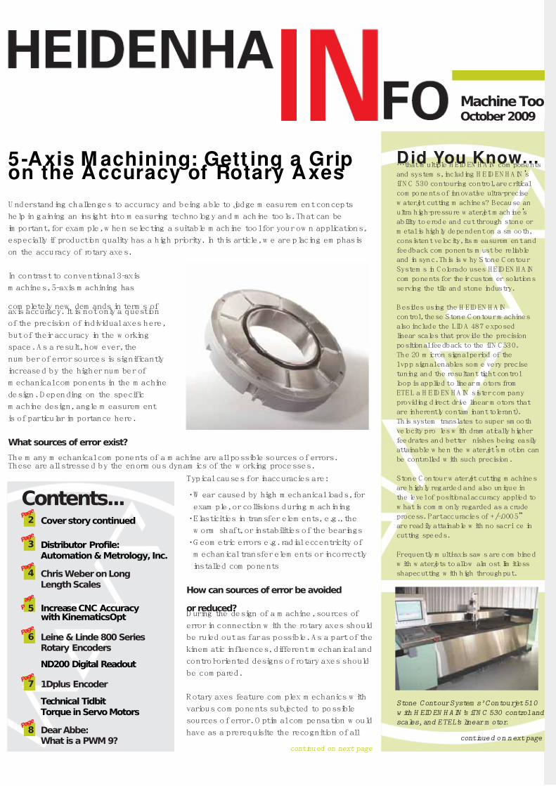
Stone Contour System s’ Contourjet 510
w ith H EID EN H AIN ’s iTN C 530 control and
scales, and ETEL’s linear m otor.
Typical causes for inaccuracies are:
•W ear caused by high m echanical loads, for
exam ple, or collisions during m achining
•Elasticities in transfer elem ents, e.g., the
w orm shaft, or instabilities of the bearings
•G eom etric errors e.g. radial eccentricity of
m echanical transfer elem ents or incorrectly
installed com ponents
How can sources of error be avoided
or reduced?D uring the design of a m achine, sources of
error in connection w ith the rotary axes should
be ruled out as far as possible. A s a part of the
kinem atic influences, different m echanical and
control-oriented designs of rotary axes should
be com pared.
R otary axes feature com plex m echanics w ith
various com ponents subjected to possible
sources of error. O ptim al com pensation w ould
have as a prerequisite the recognition of all
…that m ultiple H EID EN H A IN com ponents
and system s, including H EID EN H A IN’s
iTN C 530 contouring control, are critical
com ponents of innovative ultra-precise
w aterjet cutting m achines? Because an
ultra high-pressure w aterjet m achine’s
ability to erode and cut through stone or
m etal is highly dependent on a sm ooth,
consistent velocity, its m easurem ent and
feedback com ponents m ust be reliable
and in sync. This is w hy S tone C ontour
System s in C olorado uses HEID EN H A IN
com ponents for their custom er solutions
serving the tile and stone industry.
B esides using the H EID EN H AIN
control, these Stone C ontour m achines
also include the LID A 487 exposed
linear scales that provide the precision
positional feedback to the iTN C 530.
The 20 m icron signal period of the
1vpp signal enables som e very precise
tuning and the resultant tight control
loop is applied to linear m otors from
ETEL a H EID EN H A IN sister com pany
providing direct drive linear m otors that
are inherently contam inant tolerant).
This system translates to super sm ooth
velocity pro les w ith dram atically higher
feedrates and better nishes being easily
attainable w hen the w aterjet’s m otion can
be controlled w ith such precision.
Stone C ontour w aterjet cutting m achines
are highly regarded and also unique in
the level of positional accuracy applied to
w hat is com m only regarded as a crude
process. Part accuracies of +/-.0005”
are readily attainable w ith no sacri ce in
cutting speeds.
Frequently m ulti-axis saw s are com bined
w ith w aterjets to allow alm ost lim itless
shapecutting w ith high throughput.
continued on next page

7/17/2019 1009_mt
http://slidepdf.com/reader/full/1009mt 2/8
possible error sources for every
situation. A nd exactly that is not
possible.
A possibility for getting a grip
on position deviations of rotary
axes is the use of a suitable
H EID EN H A IN angle encoder. For
better understanding of the effect,
here are tw o basic strategies for
the design of rotary axes in control
loops:
–“Sem i-C losed Loop”
If the position of the rotary axis is
m easured solely via the rotary encoder on the m otor, then w e
refer to a “sem i-closed loop”. N ot only is the lack of accuracy ofthe m otor encoder significant w ith this arrangem ent, but m any
other errors also play a part such as w ear, elasticity deviations
and geom etric errors of the m echanical transfer elem ents.
–“Closed Loop”
If an angle encoder m ounted directly on the rotary axis is used
for position m easurem ent, m ost sources of error can be avoided.
This m ethod is know n as the “closed loop”m ethod. U se of
an angle encoder w ith integral bearing is recom m ended in this
respect so that the previously described elasticity deviations
do not lead to additional angle deviation. W hen using an angle
encoder w ith integral bearing, it is presum ed that the m inim al
angle error of an axis lies w ithin the system accuracy of the angle
encoder (the accuracy of an angle encoder of ± 2’’corresponds
to a deviation of ± 5 µm for a table diam eter of 1 m ).
O f course spatial deviations also accum ulate due to elasticity
of the axes. A ngle encoders w ith integral bearing and a hollow
shaft have an additional advantage: an integrated coupling that
com pensates for shifts of the axis m idpoints w ithout additional
angle errors. O n the other hand, angle encoders w ithout integral
bearing w ould lead to eccentric deviations and w ould therefore
provoke additional angle errors.
Are direct drives a
positive trend?
W ith respect to accuracy, direct
drives have several advantagesand hardly any disadvantages.
In the m id-term , an extensive
transition from m echanical
transfer elem ents w ith servo
m otors to direct drives (torque
m otors) can be expected. The
decisive advantage is the very
stiff coupling of the drive to
the feed com ponent w ithout
any other m echanical transfer
elem ents. This is of true
significance for a high level of contour constancy and optim al
surface quality.
W ith the use of direct drives, an additional rotary encoder
for speed definition is required. Position and shaft speed are
defined by the angle encoder m ounted directly to the rotary
axis: a “closed loop”. Since there is no m echanical transm ission
betw een the speed encoder and the feed unit, the angle encoder
m ust have a correspondingly high resolution and signal quality in
order to allow exact speed control, particularly at slow speeds.
Conclusion
System errors can be avoided w ith the selection of suitable
m easuring technology. That applies in particular to rotary axes.
B ecause of their com plexity, accuracy is a m ajor challenge.
Especially w ith interpolated 5-axis m achining and direct drive
technology, encoders that do not convert unavoidable spatial
deviations into large-scale angle errors are recom m ended.
This challenge can be m astered w ith angle encoders (w ith
integral bearing, integrated coupling and absolute position
m easurem ent) directly m ounted on the rotary axis (such as
the RC N m odel).
continued on page 3
Did you know continued from Page 1
2
Because of this, the iTN C 530 w as a natural
control choice for these m ultiprocess system s.
“The iTN C 530 adapts easily to com plicated
pallet and toolchanging system s allow ing
m any processes to be com bined in a singlecoordinate system ,”said C raig Lally, President
of Stone C ontour System s. “This includes W et
Routers utilizing diam ond tooling, as polishing
tooling w ears quickly and often necessitates
very dynam ic tool m anagem ent.”
The organized and ef cient interface of the
iTN C 530 control allow s m ultiprocess
system s to be operated m ore gracefully than
PC controls that are m ore com m on in the
industry. The exibility of program m ing inH EID EN H A IN conversational (.h) or ISO G code
(.i) accom m odates any operational situation.
Shops new to C N C can easily program in this
m ethod w ith FK (free contouring) function
being especially useful in countertop design.
Those w ith existing C A D /CA M can quickly
be adapted to the iTN C 530 w ith de nable
M codes and cycles to m atch their other
equipm ent. The N C interface is clean enough to
be foisted upon even the m ost novice operator.O EM de nable soft keys can com m and any
system process or cycle allow ing com plicated
operations to be reduced to a single, graphical
soft key.
5-axis machining continued from Page 1
HEIDENHAINangle encoder
Rotary axis
Rotary tableof the toolmachine
7/17/2019 1009_mt
http://slidepdf.com/reader/full/1009mt 3/8
continued on page 43
The best solution is angle encoders w ith integral bearing,
integrated coupling and absolute position m easurem ent,
directly m ounted to the rotary axis.
Angle encoders
The term angle encoder is typically used to describe
encoders that have an accuracy better than ± 5”.
In contrast, rotary encoders are encoders that typically
have an accuracy w orse than ± 12”. A ngle encoders
are found in applications requiring precision angular
m easurem ent to accuracy w ithin several arc seconds.
These include rotary tables and sw ivel heads on m achine tools,
C axes of lathes, m easuring m achines for gears, printing units
of printing m achines, spectrom eters, telescopes, etc.
The follow ing m echanical design principles can be defined:
•Angle encoders w ith integral bearing, hollow shaft
and integrated stator coupling
•Angle encoders w ith integral bearing for separate
shaft coupling
•Angle encoders w ithout integral bearing
5-axis machining continued from Page 2
Focusing on high technology
in both product offering
and m arketing has givenH EID EN H AIN distributor
Autom ation & M etrology Inc.
(AM I), headquartered in the
Cleveland, O hio area, a leg up
in the industry. O riginating in
1987 by a form er H EID EN H A IN
em ployee, AM I has grow n to
becom e a key distributor for
H EID EN H AIN in a relatively
short period of tim e, w ith
tw o current O hio locations,
Cleveland and Cincinnati.
“W e pride ourselves on
providing high quality
H EID EN H AIN product,
installation and service for all types of m achines in not only the
M idw est or tri-state area, but also outside of our im m ediate
geographic,”said A M I partner, M ark C ontorno, w ho purchased
the business in 2003 w ith D ave D enm an. “O ur business has
grow n ve-fold since joining the rm a decade ago. D ave and I
have strong strategies in place and have operated consistently
w ith double-digit grow th.”AM I’s custom er base –w hile in
m achine tool, aerospace, bearing
m anufacturing and m edical
equipm ent –varies in theirrequirem ents, they have all com e t
expect the com m itm ent to integrit
and service exhibited by A M I.
B oth currently in their 30s,
M ark and D ave em brace new
technologies and are alw ays
nding w ays in w hich to w ork w ith
them . “Besides the regular use
of online m arketing opportunities
using the H EID EN H AIN nam e to
reach prospects, w e also are rm
believers in regular com m unication
to our existing custom ers,”said
M ark, “O ur custom ers are alw ays
being updated on the latest
H EID EN H AIN technology being offered. W e invest in regular visits
to our custom ers w hich keeps our nam e fresh in their m inds w he
a new application com es up.”
Although A M I approaches the m arket w ith young eyes, they are
w ell rooted in w ays of the past. “Richard W alsh, the previous
Distributor Profi le: AM I Finds Ways to GrowCleveland, OH
For comparison: Accuracy of linear axes
A s w ith angle encoders, linear encoders can also significantly
increase the accuracy of feed axes. A nd here as w ell –as
is often the case w ith H EID EN H A IN –m any influences arerendered unim portant by the design: If a linear encoder is
used for m easurem ent of the slide position, the position
control loop covers the com plete feed com ponent.
Play and inaccuracies in the transfer elem ents of the
m achine have no influence in this case on the accuracy of
the position m easurem ent. M easurem ent accuracy reallyonly depends upon the precision and installation location
of the linear encoder.
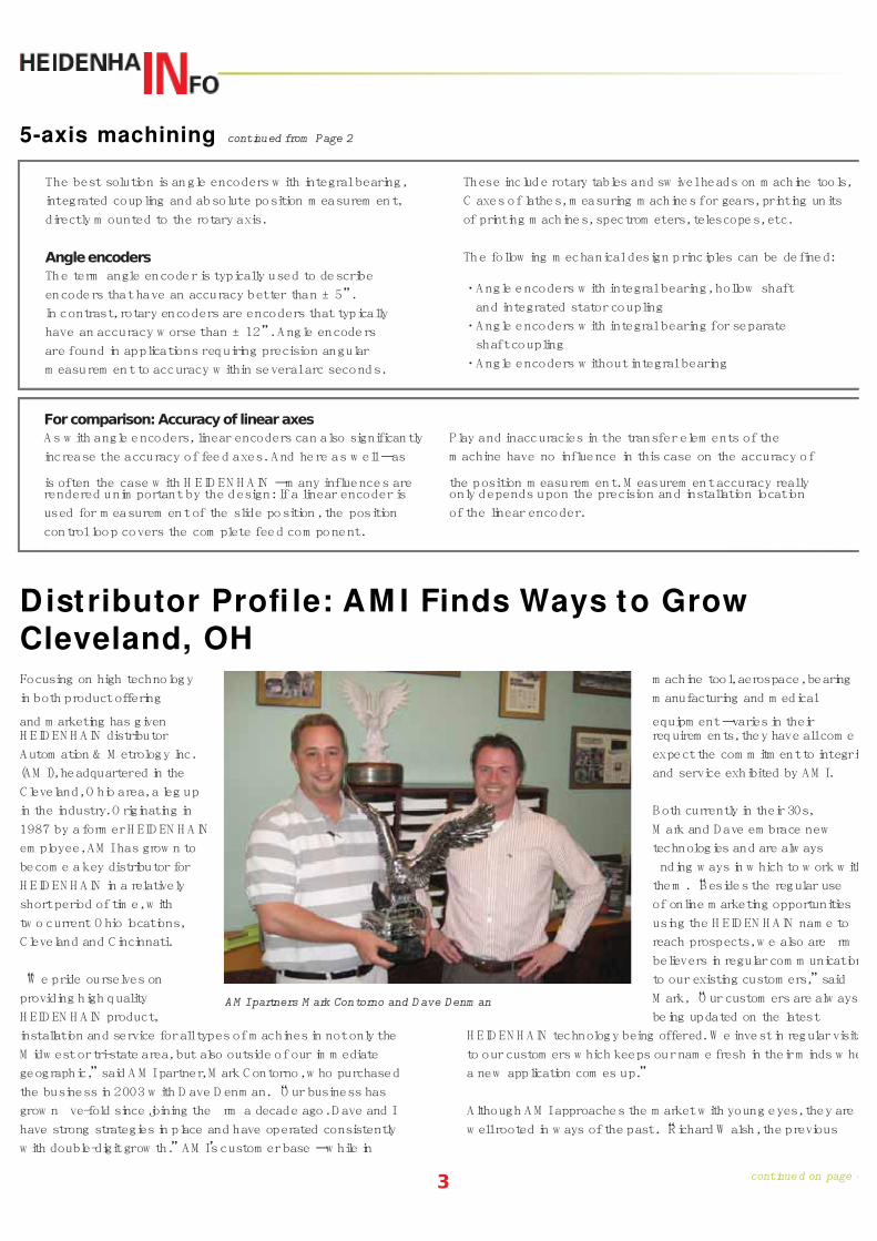
AM I partners M ark Contorno and D ave Denm an

7/17/2019 1009_mt
http://slidepdf.com/reader/full/1009mt 4/8
continued on page 54
ow ner, helped us understand w hat it takes to run a successfulsm all business,”said M ark. “This is truly paying off during
these dif cult econom ic tim es. And Rick G los (now retired
H EID EN H AIN vice president) w as a great infl uence to m e as I
started out representing H EID EN H AIN .”
W hat m akes A utom ation and M etrology successful? “W e believe
that our ‘claim to fam e’is our know ledge and ability to handle
repairs w ithin 24 hours,”said M ark. “For exam ple, because
of our full stock and in-house equipm ent in our Cleveland and
Cincinnati of ces, a custom er can com e in w ith an encoder issue
and w e can rebuild it w hile he w aits. For jobs further aw ay, w e
pride ourselves on the ability to be on site on any national job
w ithin 24 hours, and x the problem quickly.”
N ot going unnoticed, AM I has received m ultiple aw ards from
H EID EN H AIN , including tw o H EID EN H AIN D istributor of Year
President aw ards (2007 and 2003), as w ell as ten H EID EN H AIN
D istributor of the M onth aw ards over the years. “W e are thrilledto w ork w ith H EID EN H A IN and it is our rst choice w hen w e
retro t any m achine. A M I has offered other brands in the past
but over the past num ber of years, w e have m igrated to the
H EID EN H AIN brand exclusively”said M ark. “The product is
alw ays being developed and this has given us a com petitive edge
in our m arket.”
N ot only does A M I have great con dence in the product, they
also believe in the m anagem ent. “The m anagem ent and the
support are outstanding. O ur com pany know s w e can pick up
the phone and get our problem s solved, w hether it is a technical,
delivery or support issue. Just for these reasons alone, it has
m ade it easy for us not to offer any alternative to H EID EN H AIN .”
Because of AM I’s dedicated focus on m otion control technology,
they cite strong know ledge of the H EID EN H AIN product line,
w hich often saves their custom ers m oney. “W ithout this
know ledge, you are just a quoting m achine,”said M ark. “W e
specify the right com ponents for the job and get the installation
or repairs right the rst tim e. W e are strong believers in
exam ining old technology and enhancing it w ith new and all that
that has to offer.”
For more information about AMI, visit www.auto-met.com
Distributor Profile continued from Page 3
W hen it com es to big
m achines, and I m ean really
big m achines, feedback
requirem ents can be
challenging. Traditional
feedback m ethods includedsystem s such as “rack
& pinion”, low accuracy
m agnetic tapes, draw
w ire encoders, and glass
butted to glass, but all of
those system s involved
com prom ises, typically w ith regards to accuracy and long
term stability. For over 20 years, H EID EN H A IN has been
m aking sealed linear encoders for lengths of up to 100 ft
and beyond, and doing so w ithout com prom ise.
H EID EN H A IN’s longest scale system s are the LB s w hich
utilize a reflective stainless steel tape w ith a gold graduation
(currently 40 µm ) as the m easuring standard providing a
one-piece m easuring system w ith 5 µm /m eter accuracy.
A series of alum inum extrusions are used to house this
tape providing protection from contam ination and anaccurate m ounting surface. Tw o end caps secure the tape
and provide a pre-determ ined tension factor. The beauty of
stainless steel is that it has a sim ilar coefficient of expansion
as the m achine itself and in m any cases the w orkpiece thus
m itigating therm ally induced errors.
The LB system is available in standard version and m irror
im age version (for gantry applications), and w ith its distance-
coded reference m arks, a very short traverse w ill re-establish
By Chris W eber, Product M anager, M achine Tool
Going to Great Lengths with HEIDENHAIN Scales

7/17/2019 1009_mt
http://slidepdf.com/reader/full/1009mt 5/8
5
reference position. G one are the days of m oving long axes to
one end of the m achine to reestablish hom e position.
The aircraft industry has been the chief recipient of the
benefits of this system in recent years in applications from
w ing spar m anufacturing,
to drilling/riveting, carbon
fiber placem ent and
w aterjet cutting. W ith
aircraft getting larger
(A 340 and 787), the LB
382 scales system has gained in popularity and m arket share.
H EID EN H A IN C orporation recently sold and installed tw o of
these LB system s in M ichigan, each w ith a travel of over 240’
(look for a feature article on this application in a future issue of
H eidenhaIN FO ).
In fact, in the last 20 years, H EID EN H A IN has sold over 130
m iles of LB scale system s around the w orld, w hich is roughly
equivalent to driving from Los A ngeles to San D iego or
W ashington D C to P hiladelphia.
So w hat does the
future hold? C urrently
under developm ent is
the absolute version
of this scale w hich w ill
feature the purely serial
EnD at 2.2 interface providing not only long m easuring ranges
but also no requirem ent to reference, as w ell as the ability to
transm it not only position but also additional data betw een the
m easuring and control system s. Stay tuned.
Great Lengths continued from Page 4
H EID EN H AIN LB scale
C om m itted to providing continuous advancem ents in the area
of user-friendly CN C s, H EID EN H A IN C orporation now offers
a new option to its already versatile iTN C 530 contouring
control, m aking possible the autom atic
m easurem ent and com pensation
of m achine angular axes. C alled
Kinem aticsO pt, this new softw are option,
coupled w ith a m ounted H EID EN H A IN
touch probe into the C N C m achine
spindle, increases the accuracy of this
already high functioning control. The
iTN C 530 can control up to 13 axes
and a spindle.
The introduction of Kinem aticsO pt
is the answ er to C N C accuracy
requirem ents becom ing increasingly
stringent, particularly in the area of 5-axis
m achining. W ith Kinem aticsO pt, it does
not m atter w hether the individual axis
being m easured is a rotary table, tilting
table or sw ivel head. The m easurem ent
process is the sam e.
The procedure begins after having defined the m easurem ent
resolution and the area of each rotary axis that is to be
m easured. The operator then initiates probing of a calibration
ball fixed at any position on the m achine table.
From the m easured values, the iTN C 530
calculates the statistical tilting accuracy, w ith the
Kinem aticsO pt softw are m inim izing the spatial
error arising from the tilting m ovem ents.
A t the end of the m easurem ent cycle, the m achine
geom etry is saved in the respective m achine
constants of the kinem atic table. A com prehensive
log file is also saved, recording the actual
m easured cycles and the optim ized dispersion
(m easure of the statistical tilting accuracy) as
w ell as actual com pensation values.
This softw are developm ent follow s other
H EID EN H A IN productivity-enhancing control
additions such as the follow ing:
•Adaptive Feedrate C ontrol (A FC )
•D ynam ic C ollision M onitoring (D C M )
•D XF C onverter
HEIDENHAIN Increases CNC Accuracy w ithNew KinematicsOpt
Kinem aticsO pt-TS740

7/17/2019 1009_mt
http://slidepdf.com/reader/full/1009mt 6/8
6
W ith the introduction of the Leine &
Linde 800 Series rotary encoders, parent
com pany H EID EN H A IN C orporation now
offers a line of encoders that are regarded
am ong the m ost robust, m aintenance-free
and cost effective encoder solutions on
the m arket today. In addition, this series
can optionally be offered w ith A D STM
(A dvanced D iagnostics S ystem ), a built-
in system used for condition-based or
preventative m aintenance, guaranteeing
the reliability of the intended application.
The Leine & Linde 800 Series encodersare w idely used for m otor feedback in the
paper & pulp, steel and m ining industries
w orldw ide. They have also becom e the
m arket’s leading choice for generator feedback in
w ind turbines.
The 800 Series com es in shafted and hollow -
shafted versions, w ith the ceram ic bearing
option m axim izing encoder lifetim e. The series
is characterized by a dynam ic and flexible range
of pulse rates and electrical output com binations
including a dual encoder solution. For hazardous
applications, explosion-proof ATEX-certified
encoder options are offered.
The 800 Series is one of the cornerstones in
the Leine & Linde product portfolio w here highquality flexible encoder solutions that m ake use
of state-of-the-art technology are the essence of
the business.
A nsw ering the dem and for a single-axis position display that
could be m ore fully integrated into a m achine data transfer
netw ork, H EID EN H A IN introduces the N D 200 S eries D igital
R eadouts (D R O s). This display series hosts m ultiple inputs, is
flexible in its configuration, is suitable
for future absolute length gauges and
features com prehensive functions.
These new est single-axis N D 200 D R O s
com e in tw o variants: the N D 280
featuring standard functions (w ith
m onochrom e flat screen) to fulfill
m any m easuring tasks and the N D 287
(w ith color flat screen) w hich is m odularin design and allow s up to four inputs.
This feature allow s toggling betw een m ultiple gauges,
sensors and encoders to be done easily.
W ithin the H EID EN H A IN N D 287, three additional axis
m odules are incorporated. Tw o of them are analog, w hich
perm it the connection of analog sensors (such as tem perature
and pressure) and purely serial EnD at 2.2 units, w hich allow s
for the connection and full use of absolute encoders. A lso,
this D R O can be integrated into the Ethernet facilitating
rem ote m onitoring.
SPC (Statistical Process C ontrol) is now also available on
the H EID EN H A IN N D 287, allow ing the ability to w rite up to
10,000 m easured values to an internal m em ory and evaluate
them statistically.
B oth the N D 200s com e equipped w ith
a card for gauge hookup (com m on use)
and are an im provem ent over past
H EID EN H A IN single-axis D R O s as they
sport new features. A m ong these are
the ability to design functional equations
to m anage interconnected operations of
m ultiple axes and soft keys, w hich provide
m any benefits w ith regard to operationand param eter setting. These units can
display both linear and angle/rotary encoders, as w ell reading
distance-coded reference m arks. Encoders w ith E nD at 2.2 can
be connected to both.
The height and w idth of the both units result from the
requirem ent that they be suitable for installation in a 19-inch
rack. This m akes it possible to m ount tw o position displays
side by side in an electrical cabinet of this standard.
Heavy Duty 800 Series Encoders fromL& L Hold Tough in Rough Environments
Leine & Linde m odel 862, a robust
increm ental encoder solution and a
top choice for harsh environm ents
New HEIDENHAIN DRO Systems for GaugingGive More Opt ions to Netw ork
Single-Axis N D 200 D RO s

7/17/2019 1009_mt
http://slidepdf.com/reader/full/1009mt 7/8
continued on page 57
HEIDENHAIN’s Revolutionary2-Dimensional Encoder
Introducing an exciting new
dim ension to m easurem ent,H EID EN H A IN C orporation presents
the 1D plus encoder. A fter m uch
R & D , this uniquely innovative tw o-
dim ensional encoder w as designed
in order to allow m easurem ent
of linear guiding and therm al
drift errors during m ovem ents
of a stage or m achine, allow ing
the processing and im m ediate
com pensation of these errors. This
results in a system w ith very high
accuracies w ith jobs done right the
first tim e.
The m ost likely current applications for the 1D plus include use
in stacked stages, precise gantries, w afer processing, and in
large flat panel display production and tests, though any m otion
stage user w ho w ants to increase perform ance w ould benefit.
These truly revolutionary 1D plus encoders are frictionless
and have gratings in tw o dim ensions, w ith m odels featuring
tw o or three scanning units for sim ultaneous m easurem ent
of both the X and Y directions. Three scanning units allow
the calculation of the angle
of rotation of the bracket thathouses the scanning units.
These orthogonal encoder
graduations provide an exciting
new dim ension in precision as
the encoder system m easures
left and right (X axis), the up-
and-dow n (Y axis) m otion is
m easured (and com pensated for
by the control) as w ell.
H EID EN H A IN ’s early and current
1D plus encoders are in use as
the H EID EN H A IN interferential-
type linear encoder, the LIF 400 w ith 1D plus (see im age).
The m easuring standard is D IA D U R w ith a therm al expansion
coefficient of 0 ppm /K. C urrent m easuring length is 300 x 2
m m , w ith plans to increase that dram atically. The 1D plus scale
itself is 20 x 4.9 m m .
The X-axis m easurem ent of the1D plus has a current accuracy
grade of ± 1 µm and includes a reference m ark. The grating
period of the encoder is 8 µm ; the signal period is 4 µm .
Technical Tidbit:
Torque in Servo Motors
W hen specifying servo m otors for a new m achine or C N C
retrofit, there are m any specifications regarding servo
m otor perform ance. O ne of the m ost confusing is the
differing torque specifications of the m otor. Torque can be
specified in N ew ton m eters (N m ) or m ore com m only foot
pounds (lb-ft) or inch pounds (lbf-in).
1N m = 0.74 lbf-ft = 8.85 lbf-in
Torque (also called m om ent of force) can be defined as:
The m echanical w ork generated by the turning effect
produced w hen force is applied to a rotational axis. O r the
m easure of how m uch a force acting on an object causes
that object to rotate.
R ated Torque (M N ) - The m axim um continuous torque
available at the rated speed that allow s the m otor to do
the w ork w ithout overheating (typically specified at a
tem perature). This is the w orking range of the m otor.
Stall Torque (M O ) - The torque, w hich is produced by
a device w hen the output rotational speed is zero or
the torque load that causes the output rotational speed
of a device to becom e zero –i.e. to cause stalling.
M ax. Torque (M m ax) - A lso know n as peak torque, the
greatest am ount of torque the m otor can generate for
a very short tim e period (typically specified in m s).
W hen specifying servo m otors for a m achine tool
application, the com m only accepted specification is
the R ated Torque.
7/17/2019 1009_mt
http://slidepdf.com/reader/full/1009mt 8/8
8
Answer: The P W M 9 is a com plete universal m easuring unit
for inspecting and adjusting H EID EN H A IN increm ental linear
and angle encoders. Instead of offering just a series of LE D s
on the encoder for installation w hich
can lead to a green light that could
just be m arginally green and cause
issues after the m achine has shipped
to the custom er, H EID EN H A IN offers
tw o devices that provide detailed
inform ation on the encoder signals
and allow s the user to install correctly,thereby increasing the safety m argin
and quality of the m achine overall.
First, the sm all low cost handheld
device that displays am plitude
inform ation to a resolution of 0.1V and
the quality of the hom e pulse is called
the P W T. There are various PW Ts for
the various electrical interfaces and
are dedicated to that interface, such
as 1Vpp or TTL. The other device, a
PW M 9, how ever has this PW T m ode
as w ell as m uch m ore detail about
the encoder signals, such as phase
angle of sine and cos w aves, encoder current consum ption
and encoder voltage and offsets. The PW M 9 has a slot w here
various electrical interface cards can be inserted, such as Endat
(increm ental analog signals only), TTL, and 1V pp. PW M 9 is
G erm an for Phasen W inkel M essung w hich translates to P hase
A ngle M easurem ent, and it is the 9th iteration of this device.
The PW M 9 is also valuable for safe
inline usage so that a user can look at
the detailed encoder signal param eters
w hile the m achine axis is put to m otion
This helps the users to determ ine if
the encoder is installed correctly and
w ith enough safety m argin throughthe w hole range of m otion of that
particular axis. Encoders w ith LED s
cannot com pare as one does not know
if certain areas of the m otion axis are
m arginally “green”or not. Encoders
using just a U SB interface for setup also
cannot be run inline w ith the m achine
axis in m otion.
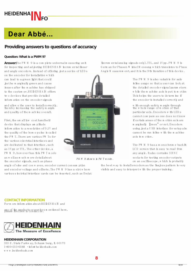
The PW M 9 has a m onochrom e backlit
LC D screen that is easy to read from
any angle. It also contains 3 B N C
sockets for testing encoder outputs
on an oscilloscope, w hich is probably
the best w ay to install encoders as the lisajous pattern is very
visible and easy to interpret w ith the proper training.
Dear Abbé...
PW M 9 show n in PW T m ode.
Providing answers to questions of accuracy
Question: What is a PWM 9?
HEIDENHAIN CORPORATION333 E. State P arkw ay, Schaum burg, IL 60173
1-800-233-0388 •info@ heidenhain.com
w w w .heidenhain.com
CONTACT INFORMATIONFor m ore inform ation about H EID EN H AIN and
any of the products or services m entioned here,please feel free to contact us.


