10.0000@@generic-FCE0E5A81EDA.pdf
13
Journal of Environmental Protection, 2014, 5, 1630-1640 Published Online December 2014 in SciRes. http://www.scirp.org/journal/jep http://dx.doi.org/10.4236/jep.2014.517154 How to cite this paper: Wahyuningsih, S., Purnawan, C., Saraswati, T.E., Pramono, E., Ramelan, A.H., Pramono, S. and Wis- nugroho, A. (2014) Visible Light Photoelectrocatalytic Degradation of Rhodamine B Using Ti/TiO 2 -NiO Photoanode. Journal of Environmental Protection, 5, 1630-1640. http://dx.doi.org/10.4236/jep.2014.517154 Visible Light Photoelectrocatalytic Degradation of Rhodamine B Using Ti/TiO 2 -NiO Photoanode Sayekti Wahyuningsih, Candra Purnawan, Teguh E ndah Saraswati, Edi Pramono, Ari Handono Ramelan, Setyo Pramono, Ari Wisnugroho Inorganic Material Research Group, Department of Chemistry, Faculty Mathematics and Natural Science, Sebelas Maret University, Surakarta, Indonesia Email: [email protected] Received 22 September 2014; revised 18 October 2014; accepted 12 November 2014 Copyright © 2014 by authors and Scientific Resear ch Publishing Inc. This work is licensed under the Creative Commons Attributi on International License (CC BY). http://creativecommons.org/licenses/by/4.0/ Abstract The method of Ti/TiO 2 -NiO photoelectrode prepared by using sol-gel method continued by calci- nation process was introduced. The prepared TiO 2 -NiO film was observed with XRD and TEM. The anatase-rutile TiO 2 was mainly on the prepared TiO 2 -NiO composite surface electrode. In addition to NiO, the composite also formed NiTiO 3 that increased with increasing calcination temperature. Photoelectrocatalytic degradation of Rhodamine B (RB) using this electrode was investigated, and anodic potential and pH were optimized. RB degradation was investigated under different condi- tions, and it showed that photoelectrocatalytic degradation could achieve efficient and complete mineralization of organic pollutant. Through comparison of the photoelectrocatalytic oxidation using the Ti/TiO 2 -NiO electrode operated by single photoanode with the Ti/TiO 2 -NiO electrode operated by several photoanode, it was found that the photoelectrocatalytic efficiency of that by series photoanodes was higher. Additionally, photoelectrocatalytic system was performed at the several different photoelectrodes, which verified the higher photocatalytic activity compared with the single photoelectrode. Keywords Ti/TiO 2 -NiO Photoelectrode, Visible Light, Photoelectrocatalysis Degradation, Rhodamine B 1. Introduction Titanium dioxide (TiO 2 ) was widely used in photocatalytic degradation of the organic pollutants that could not
-
Upload
ari-wisnugroho -
Category
Documents
-
view
227 -
download
0
Transcript of 10.0000@@generic-FCE0E5A81EDA.pdf
8/9/2019 [email protected]@generic-FCE0E5A81EDA.pdf
http://slidepdf.com/reader/full/100000wwwscirporggeneric-fce0e5a81edapdf 1/12
Journal of Environmental Protection, 2014, 5, 1630-1640
Published Online December 2014 in SciRes. http://www.scirp.org/journal/jep
http://dx.doi.org/10.4236/jep.2014.517154
How to cite this paper: Wahyuningsih, S., Purnawan, C., Saraswati, T.E., Pramono, E., Ramelan, A.H., Pramono, S. and Wis-
nugroho, A. (2014) Visible Light Photoelectrocatalytic Degradation of Rhodamine B Using Ti/TiO2-NiO Photoanode. Journal
of Environmental Protection, 5, 1630-1640. http://dx.doi.org/10.4236/jep.2014.517154
Visible Light PhotoelectrocatalyticDegradation of Rhodamine B Using
Ti/TiO2-NiO Photoanode
Sayekti Wahyuningsih, Candra Purnawan, Teguh Endah Saraswati, Edi Pramono,
Ari Handono Ramelan, Setyo Pramono, Ari Wisnugroho
Inorganic Material Research Group, Department of Chemistry, Faculty Mathematics and Natural Science,
Sebelas Maret University, Surakarta, Indonesia
Email: [email protected]
Received 22 September 2014; revised 18 October 2014; accepted 12 November 2014
Copyright © 2014 by authors and Scientific Research Publishing Inc.
This work is licensed under the Creative Commons Attribution International License (CC BY).
http://creativecommons.org/licenses/by/4.0/
AbstractThe method of Ti/TiO2-NiO photoelectrode prepared by using sol-gel method continued by calci-
nation process was introduced. The prepared TiO2-NiO film was observed with XRD and TEM. The
anatase-rutile TiO2 was mainly on the prepared TiO2-NiO composite surface electrode. In addition
to NiO, the composite also formed NiTiO3 that increased with increasing calcination temperature.
Photoelectrocatalytic degradation of Rhodamine B (RB) using this electrode was investigated, and
anodic potential and pH were optimized. RB degradation was investigated under different condi-
tions, and it showed that photoelectrocatalytic degradation could achieve efficient and complete
mineralization of organic pollutant. Through comparison of the photoelectrocatalytic oxidation
using the Ti/TiO2-NiO electrode operated by single photoanode with the Ti/TiO2-NiO electrode
operated by several photoanode, it was found that the photoelectrocatalytic efficiency of that by
series photoanodes was higher. Additionally, photoelectrocatalytic system was performed at the
several different photoelectrodes, which verified the higher photocatalytic activity compared with
the single photoelectrode.
Keywords
Ti/TiO2-NiO Photoelectrode, Visible Light, Photoelectrocatalysis Degradation, Rhodamine B
1. Introduction
Titanium dioxide (TiO2) was widely used in photocatalytic degradation of the organic pollutants that could not
8/9/2019 [email protected]@generic-FCE0E5A81EDA.pdf
http://slidepdf.com/reader/full/100000wwwscirporggeneric-fce0e5a81edapdf 2/12
S. Wahyuningsih et al .
1631
be degraded easily such as dyes because of its favorable physical, chemical and photocatalytic properties andhigh stability [1]-[8]. This photocatalytic method was based on the reactive properties of photogenerated elec-tron-hole pairs. They were generated in the semiconductor (TiO2) particles under irradiation at suitable wave-lengths ( λ ≤ 400 nm). These electrons and holes could also recombine. Since the hole was a powerful oxidizingagent, it could decompose contaminants adsorbed on the TiO2 surface. Meanwhile, it could also oxidize water to
produce hydroxyl radicals that could decompose organic pollutants in water [9]-[12]. There were many reportson photoelectrocatalytic degradation of organic pollutants by using TiO2 electrodes which were prepared bycoating the surfaces of electrically conducting sub-strates (ITO, Ti) with TiO 2 film. In this method, positive po-tential was applied on the working electrode (Ti/TiO2 electrode), which could inhibit the recombination of elec-trons and holes and enhance the efficiency of photocatalytic degradation of organic compounds [5] [6] [13]-[18].
In order to improve the photoelectrocatalytic capability of TiO2 film, preparation of TiO2 film was extensivelystudied. TiO2 films were often prepared by using either sol-gel method [19]-[25], pray pyrolysis [26] or sputter-ing [27]. Metal oxides, such as CuO, Cu2O, Fe2O3, WO3, MoO3, ZnO, NiO, SnO2, and so on, have been consi-dered for band-gap engineering of TiO2 as these oxides have compatible processing strategies with TiO2 [28]-[37]. Among these oxides, low band-gap CuO or NiO is used as sensitizers to use visible radiation, whereasother large band-gap oxides (e.g., ZnO, SnO2) are coupled with TiO2 for extrinsic trapping of photogeneratedcharge carriers to enhance photoactivity. Among these, coupling TiO2 with NiO still attracts less attention. The
band gaps of SnO2 and TiO2 are 3.80 and 3.2 eV [38], respectively, and the CB edge of NiO is 0.5 V above thatof TiO2 [39]. When the two semiconductor particles are coupled, the CB of NiO acts as a sink for photogene-rated electrons. Since the photogenerated holes move in the opposite direction, they accumulate in the VB of theTiO2 particle, which increases the efficiency of charge separation.
In this paper, Ti/TiO2-NiO electrode was prepared by using sol-gel method. The crystalline structure and sur-face morphology of TiO2 film were evaluated by using X-ray diffraction (XRD) and TEM. The effect of crystal-line size and structure was discussed. The photoelectrocatalytic ability of this electrode for degradation of Rho-damine B (RB) (Figure 1) and the effect of anodic potential and pH on this photoelectrocatalytic reaction wereinvestigated. The photoelectrocatalytic oxidation using the Ti/TiO2-NiO electrode calcinated by furnace wascompared. Additionally, photoelectrocatalytic oxidation measurements were performed at the variously counterelectrodes of Ti (commercial), Ti/TiO2, which indicated the higher photocatalytic activity of the Ti/TiO2 elec-trode further.
The mechanism of the RB photodegradation may include the following possible steps [40]:
2RB O 2 rhodamine products−•
+ → → (1)
2RB TiO (e ) 2 rhodamine products−
+ → → (2)
RB OH RB OH• +• −
+ → + (3)
2RB O 2 rhodamine products+• −•
+ → → (4)
The cationic dye radical of RB is degraded into carbon dioxide, water, and mineral acids through a rhodamineintermediate. The rhodamine intermediate could be detected by UV-VIS spectroscopy from approximately 240nm to 360 nm. In principle, the degradation process of RB decreases the absorption peak at 543 nm, but in-creases absorption peaks at approximately 240 - 360 nm. Qu et al. (1998) [28] reported that OOH• and OH• arenecessary for the N -de-ethylation of RB, which, in turn, is necessary for complete degradation of the dye.
Figure 1. Structure of Rhodamine B.

8/9/2019 [email protected]@generic-FCE0E5A81EDA.pdf
http://slidepdf.com/reader/full/100000wwwscirporggeneric-fce0e5a81edapdf 3/12
S. Wahyuningsih et al .
1632
2. Experiment
2.1. Reagent
Titanium (99.7%, in area 10 cm × 3 cm) was purchased from the Far East Ti Equipment Co., Shanghai, China.RB, titanium tetraisopropoxide (TTIP), ethanol, acetic acid, nickel chloride and other chemical reagents were
purchased from E. Merck (Indonesia). All reagents were of analytical reagent grade quality. All solutions were prepared with doubly distilled water.
2.2. Device
X-ray data were collected by using a D8ADVANCE X-ray diffractometer (Bruker axs Co., Germany) based onCuK α radiation. The 2θ (two-theta) angle of the diffractometer was stepped from 10˚ to 80˚ by 0.03˚ increments.Transmission Electron microscope (TEM) was obtained by a JOEL JEM 1400 (Japan) with an in-column energyfilter. Electrochemical experiments were performed with a Potentiostat (Jiangsu Electroanalytical Co., China).The two electrode system consisted of a Ti/TiO2-NiO electrode as the working electrode, electrode and aTi/TiO2 as the counter electrode. The radiation source was a halogen lamp (300 W, Osram).
2.3. TiO2 Film Preparation
The TiO2 film has been synthesized by procedures that have been published previously [40]. A 10 mL solutionof TTIP was hydrolysed in the 100 mL acetic acid glacial solution and mixed under vigorous stirring in an icewater- bath (10˚C - 15˚C) until a clear yellow solution of TiO2 nanocrystals was formed. The solution was heatedat 90˚C for 2 h when it became a gel , which was then placed in an oven at 150˚C for 24 h to undergo an aging
process. Next, the TiO2 xerogel was ground and pulverized into a fine powder and calcined in a muffle furnaceat 400˚C for 2 h at a heating rate of 10˚C∙min
−1. Then, ethanol was added to the TiO2 powder before dip-coatingto the Ti mesh. The TiO2-coated Ti mesh was then dried at 100˚C for 5 min. The coating and drying treatmentswas repeated three times.
2.4. TiO2-NiO Films Preparation
1.145 grams of synthesized xerogel TiO2 (previous procedure) was added in 0.81 grams of NiNO3∙6H2O that has
dissolved in 25 ml of distilled water. The mixed solution was stirred with magnetic stirrer to fuse. Then, theuniform mixture was dried at 110˚C for 3 h. To improve the crystalline TiO2-NiO after the green suspension wasformed, it was calcinated at various temperature of 150˚C, 300˚C, 400˚C, 500˚C, 600˚C, and 700˚C for 4 hours at10˚C/min. The crystalline TiO2-NiO composite was superimposed onto a SnO2F conductive glass and was driedat 110˚C for 3 h. The coating and drying treatments was repeated three times.
2.5. Photoelectrodegradation Experiment
In order to investigate the photoelectrocatalytic (PEC) activity of the prepared sensitized TiO 2 thin film, a seriesof degradation experiments of Rhodamine B in aqueous solutions were performed. The initial concentration ofRhodamine B was 5 mg∙L−1, with 0.05 mol∙L−1 of NaCl used as the supporting electrolyte. The total volume ofthe solution was 10 mL. Experiments were carried out in an optical quality quartz cell equipped with a two-electrode system. A copper wire as well as Ti plate was used as the counter electrode. The front of the working
electrode was irradiated with a 300 W visible light lamp (Halogen lamp, Osram) and the progress of the photoe-lectrocatalytic degradation was recorded at defined intervals by UV-VIS spectroscopy. The PEC degradation ofRB was performed at voltages of 1.0 V to +10.0 V and at various pH values.
3. Results and Discussions
3.1. The Characteristics of TiO2 Film
The TiO2 films prepared by sol-gel from titanium tetraisopropoxide precursor were characterized by XRD, asshown in Figure 2. The present work, the sol-gel method was carried out under acidic conditions with aceticacid as solvent. The use of acetic acid as the solvent, as well as activating the formation of Ti(OCOCH 3)(O
iPr)2 complexes, permits control of both the degree of condensation and the oligomerisation and induces preferential
8/9/2019 [email protected]@generic-FCE0E5A81EDA.pdf
http://slidepdf.com/reader/full/100000wwwscirporggeneric-fce0e5a81edapdf 4/12
S. Wahyuningsih et al .
1633
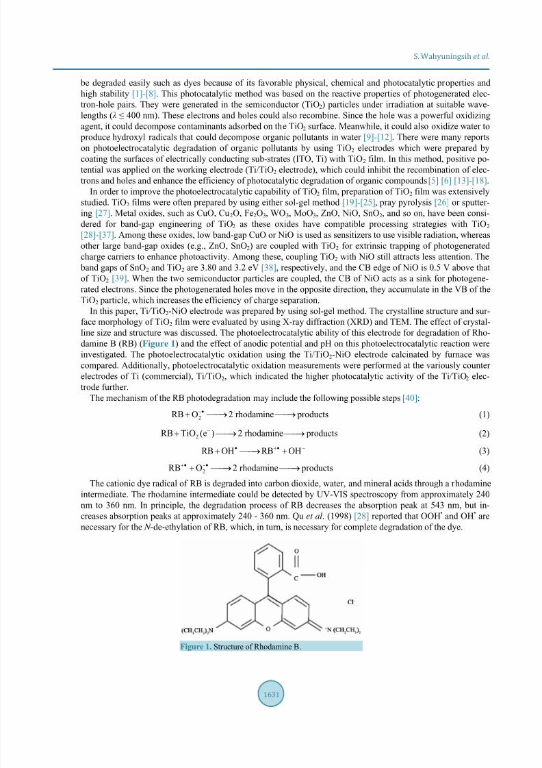
Figure 2. XRD pattern of prepared anatase TiO2.
crystallisation of TiO2 in the anatase phase. In the first case, a spherical and relatively monodisperse aggregatesof nanocrystallites could be obtained. The growth kinetics of the aggregates is determined by the stability of thecolloid. The TiO2 particles formed are relatively stable and a white suspension is gradually formed due to the precipitation of large aggregates.
However, under the acetic acid conditions using the Ti(OiPr)4 precursor, the complexes formation was occuras described in the equation below [40].
H
3 4 3 2CH COO Ti(O Pr) Ti(OCOCH )(O Pr)i i+
−
+ →
In further hydrolysis and condensation steps, the Ti(OCOCH3)(OiPr)2 product will produce nanotitania. In this
research, nano-TiO2 was prepared from stock solutions of 110 mL solution containing titanium tetraisopropox-ide and acetic acid solution in a volume ratio of 1:10 in a water bath (10 ˚C - 15˚C). The anatase of TiO2 was ob-tained after an annealing process at 400˚C (annealing rate of 10˚C min). Figure 2 shows that the XRD pattern ofthe TiO2 thus prepared exhibits strong diffraction peaks at 2θ = 25.35˚ (d 101 = 3.51 Å), 2θ = 37.90˚ (d 004 = 2.37
Å), 2θ = 48.11˚ (d 200 = 1.89 Å), 2θ = 54.16˚ (d 105 = 1.69 Å), and 2θ = 54.96˚ (d 211 = 1.67 Å), indicating that TiO2 is formed by the anatase phase. All peaks are in good agreement with the standard spectrum (JCPDS No.:JCPDS # 782-484). This result suggested that the nano-TiO2 powder was irregularly polycrystalline. The XDR pattern shows that only the anatase phase is formed.
In addition, TEM was used to further examine the crystallite/particle size, crystallinity, and morphology of thesamples. Clear spherical and non-homogeneous structures can be seen in Figure 3(a), with the average size ofthe primary particle approximately 10 nm, which is in good agreement with the value determined by XRD. The particle of TiO2 in the anatase phase has a mostly spherical morphology (Figure 2(a)). The area selected forelectron diffraction pattern analysis (SAED), confirming that the TiO2 nanoparticles are highly crystalline in theanatase phase, in good agreement with the standard JCPDS # 782-484 and XRD result.
3.2. The Characteristics of TiO2-NiO Film
The composite of TiO2-NiO was obtained after an annealing process at 700˚C (annealing rate of 10˚C min).Figure 4 shows that the XRD pattern of the TiO2-NiO thus prepared exhibits strong diffraction peaks at 2θ =27.45˚ (d 110 = 3.2452 Å ), 2θ = 36.10˚ (d 101 = 2.4849 Å ), 2θ = 39.20˚ (d 200 = 2.2952 Å), 2θ = 41.25˚ (d 111 =2.1858 Å), 2θ = 44.05˚ (d 210 = 2.0531 Å ), 2θ = 54.36˚ (d 211 = 1.6858), and 2θ = 56.66˚ (d 220 = 1.6227 Å) whichare the characterization of rutile TiO2 according to the standard JCPDS No. 870-710. There are also several peaks indicates the anatase phase at 2θ = 25.40˚ (d 101 = 3.5023 Å), 2θ = 37.90˚ (d 004 = 2.3709 Å), and 2θ =48.15˚ (d 200 = 1.8874 Å) according to the standard JCPDS No. 782-486. Peaks characteristic of NiTiO 3 are peaks at the 2θ = 24˚ (d012 = 3.6584 Å), 2θ = 33˚ (d110 = 2.6911 Å), 2θ = 49˚ (d024 = 1.8356 Å), and 2θ = 57˚ (d018 = 1.5969 Å). All peaks are in good agreement with the standard spectrums JCPDS No. 753-757.
TEM was used to further examine the crystallite/particle size, and morphology of the TiO2-NiO compositessamples. Clear spherical and non-homogeneous structures can be seen in Figure 5(a), with the average size of

8/9/2019 [email protected]@generic-FCE0E5A81EDA.pdf
http://slidepdf.com/reader/full/100000wwwscirporggeneric-fce0e5a81edapdf 5/12
S. Wahyuningsih et al .
1634
Figure 3. Images of anatase phase. (a) TEM image of nano-TiO2 powder; (b) SAED pattern of nano-TiO2 powde.
Figure 4. XRD pattern of TiO2-NiO thin film.
Figure 5. TEM Image of TiO2-NiO nanoparticle were used for photoanode preparation (a) 500 nm bar; (b) 50 nm bar.
the primary particle approximately 20 - 30 nm, which is in good agreement with the value determined by XRD.
The particle of TiO2 in the anatase phase has a mostly spherical morphology (Figure 5(a)). The area selected forelectron diffraction pattern analysis (SAED) (Figure 5(b)), confirming that the TiO2-NiO nanoparticles are alsohighly crystalline in the anatase phase, rutile phase and TiNiO3.
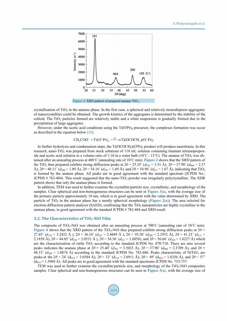
While the part of photoanoda TiO2-NiO composite shows that TiO2-NiO materials were deposited on the Ticontained on porous amorphous silica (Figure 6). The conductivity character of those composite is shown inFigure 7. The profile shows that the composite photoanoda Ti/TiO2-NiO quite well as electron generation.Based on the bar graph in Figure 8, that shows the percentage of formation of NiO in a variety of temperatures,as well as the byproducts NiTiO3. NiTiO3 arises due to the formation of NiO and TiO2. Percentage of NiO in thecomposite achieving optimum condition at 500˚C reached 22.78%. Another product is a composite of NiTiO3 that appears on composite roasted at 600˚C and roasted at 700˚C composite. Increased temperature and additionof NiO dopants were affecting the TiO2 crystalization. Increased temperature and the addition of NiO dopants
(a) (b)
8/9/2019 [email protected]@generic-FCE0E5A81EDA.pdf
http://slidepdf.com/reader/full/100000wwwscirporggeneric-fce0e5a81edapdf 6/12
S. Wahyuningsih et al .
1635
Figure 6. XRD Pattern of Ti/TiO2-NiO electrode material.
Figure 7. Voltage applied-current profile of the Ti/TiO2-NiOelectrode. Counter electrode: Ti/TiO2 electrode.
Figure 8. Relative abundance of anatase phase, rutile phase, NiO, and NiTiO3 on TiO2-NiO composite result of annealing at
300˚C (1), 400˚C (2), 500˚C (3), 600˚C (4), and 700˚C (5).
were affecting TiO2 crystal structure transformation. The addition of these dopants was found to suppress thetransformation of anatase into rutile (compared with no addition of dopand, Table 1). The occurrence of thesestructural transformations will change the photoactivity of TiO2 and further explained in TiO2-NiO compositeactivity for photodegradation of Rhodamine B.
3.3. Influence of pH
This experiment was carried out at different pH values of 2.0, 4.0, 6.0, 8.0 and 10.0, respectively, in order to in-vestigate the process of RB photoelectrocatalytic degradation. The experimental results were shown in Figure 9. It demonstrated that the efficiency of the photoelectrode on the photoelectrocatalytic degradation of RB was
R111
A104
R211
NiTiO3 110
R110

8/9/2019 [email protected]@generic-FCE0E5A81EDA.pdf
http://slidepdf.com/reader/full/100000wwwscirporggeneric-fce0e5a81edapdf 7/12
S. Wahyuningsih et al .
1636
Figure 9. Absorbance of RB solution after photoelectrocatalyticdegradation for 180 min at various pH values under visible lightirradiation ([NaCl] = 0.05 M, [RB] = 5 × 10⁻⁴ mass%, applied bias potential 1.0 V).
Table 1. Anatase to rutile ratio (A/R) of the synthesized TiO2 and composite TiO2-NiO.
A/R ratioAnnealing temperature
150˚C 300˚C 400˚C 500˚C 600˚C 700˚C
TiO2 1:0 1:0 1:0 1:0.06 1:0.72 1:9.93
TiO2-NiO composite 1:0 1:0.20 1:0.20 1:0.21 1:0.41 1:1.70
improved with the increase in pH value and the rate constant of the photoelectrocatalytic degradation of RB wasalso increased at the same time. The results showed that the photoelectrocatalytic activity of the photoelectrodewas increased due to the increase in pH value. The study of the effect of pH value on the efficiency of photoe-lectrocatalytic degradation of organic dye was valuable but complicated. Firstly, pH value had significant effecton the absorption behavior of the organic dye on the catalyst surface. The point of zero charge of the TiO2 thatwas the catalyst was at pH 6.4. Thus, the TiO2 surface was positively charged in the media with pH less than 6.4,whereas it was negatively charged under the conditions with the pH greater than 6.4. The value of pH could alsoinfluence the charge carried by the molecule [40], the molecule of RB was cationic form at lower than 4. Whenthe pH value was less on the catalyst surface became difficult because of an electrostatic repulsive force. Whenthe pH value was greater than 4, the molecule of RB was in the zwitterionic form and a certain part of the mole-cule was attracted by the catalyst surface due to the electrostatic attraction [16]. As a result, the efficiency of the photoelectrocatalytic degradation of RB was relatively low with the pH less than 4 while the efficiency was in-creased with the pH greater than 4. Secondly, the change of pH had an important effect on modifying the posi-tion of the TiO2 conduction band (60 mV per pH unit) [35]. Thus, the oxidizing ability of photogenerated holeswas raised, i.e. the hydroxyl radical production was facilitated in the oxidation of water (or hydroxide ions) by photogenerated holes. The more alkaline, the more readily water (or hydroxide ions) underwent oxidation togenerate hydroxyl radicals on the catalyst surface. Therefore, the photoelectrocatalytic degradation of RB was
more efficient due to the increase in pH value. The pH value of 10 was selected in subsequent experiments.
3.4. Degradation of RB under Different Applied Potential Bias Conditions by theProposed Photoelectrode
When the potential was 3.0 V, the rate of photoelectron transport process was lower and controlled the overallPEC oxidation. Thus, the photocurrent increased within the potential of 3.0 - 5.0 V. Once the applied bias ex-ceeded 5.0 V, the interfacial oxidation, which was slower than the photoelectron transport, became the rate-de-termining step of the overall process. Under this condition the photocurrent saturated gradually. The anodic po-tential was an important parameter in the process of photoelectrocatalytic degradation of RB. The effect of ap- plied potential was determined by using a series of potentials. To study the key factors affecting the photode-gradation of RB, a series of tests were executed under different experimental conditions in which the deduction

8/9/2019 [email protected]@generic-FCE0E5A81EDA.pdf
http://slidepdf.com/reader/full/100000wwwscirporggeneric-fce0e5a81edapdf 8/12
S. Wahyuningsih et al .
1637
of Vis absorbance was estimated.After 5 min degradation (batch system), about 96.3% of RB was removed. Photoelectrocatalytic (PEC)
experiment 1 was carried out under halogen lamp irradiation using the Ti/TiO2-NiO photoelectrode with a po-tential voltage of +10.0 V. It was obvious that the degradation rate was very fast. But their applied potential vol-tages make the electrode surface damage rapidly. Furthermore, the continuous systems were done with applied
potential bias of 4, 5, and 6 volts. The results are shown in Table 2. However, RB could not undergo completedegradation to produce CO2 and H2O, as a result, the intermediates were produced during the process [40]. Therefore, PEC method showed high complete mineralization activity in the RB degradation reaction. Figure 10 shows no prominent peak in the UV region around 370 nm as an indication of an intermediate peak of rhoda-mine.
3.5. Compared the Photoelectrocatalytic Oxidation Using Several Photoelectrodes
Compared the photoelectrocatalytic oxidation using the Ti/TiO2 electrode by batch system as well as by single photoanode (Table 2), the photoelectrocatalytic oxidation process using integrated photoanode can enhance theRB degradation, respectively, as shown in Table 3. The experimental results also demonstrated that the reactionrate of RB degradation using several electrode by continuous system was higher than that by single photoanode.
Figure 10. Electronic spectra of Rhodamine B before and after photo-electrocatalytic degradation process at a variation applied voltage.
Table 2. Degradation of RB (%) under different experimental conditions using Ti/TiO2-NiO photoanode with a300 watts halogen lamp irradiation.
Experiment Potential voltage of photoanode (volt) Batch system (%)Continuous system (%)
3 mL/sec 6 mL/sec
1 10 96.3*
2 4 10.0 14.9
3 5 12.7 15.3
4 6 15.9 16.3
Table 3. Degradation of RB (%) under different experimental conditions using several photoanode of Ti/TiO 2- NiO, Ti/TiO2-PbO, Ti/Ta-Ir and Ti/Ru-Ir photoanodes, respectively, under a 300 watts halogen lamp irradiation.
Applied bias potential of photoanode (volt)Flow rate
3 mL/sec 6 mL/sec
4 98.0 95.5
5 99.3 97.0
6 99.6 98.0
8/9/2019 [email protected]@generic-FCE0E5A81EDA.pdf
http://slidepdf.com/reader/full/100000wwwscirporggeneric-fce0e5a81edapdf 9/12
S. Wahyuningsih et al .
1638
4. Conclusion
In this paper, the method of preparation Ti/TiO2 photoelectrode was firstly presented. The anatase TiO2 wasmainly on the prepared electrode surface. Photoanode of the TiO2-NiO composite synthesized by sol-gel methodshowed that the photoelectrocatalytic degradation ran very well. Photoelectrocatalytic degradation of RB using
this electrode was investigated, and the operating conditions were optimized. pH and applied bias voltage af-fected the rate of photoelectrocatalytic degradation of Rhodamine B. By the comparison of the photoelectroca-talytic oxidation using the Ti/TiO2 NiO electrode operated by single photoanode and the TiO2 NiO electrode op-erated by several photoanode, it was found that the photoelectrocatalytic efficiency of that by series photoanodeswas higher. Additionally, photoelectrocatalytic system was performed at the several different photoelectrodes,which verified the higher photocatalytic activity of the single system-treated electrode further.
Acknowledgements
This work is supported by the STRANAS research program (Contract Number No. 6562/UN27.16/PN/2014)from Director of Higher Education Ministry of Education and Culture of Indonesia.
References
[1]
Krýsa, J., Keppert, M., Waldner, G. and Jirkovský, J. (2005) Immobilized Particulate TiO2 Photocatalysts for Degrada-tion of Organic Pollutants: Effect of Layer Thickness. Electrochimica Acta, 50, 5255-5260.http://dx.doi.org/10.1016/j.electacta.2005.01.054
[2] Usui, H., Miyamoto, O., Nomiyama, T., Horie, Y. and Miyazaki, T. (2005) Photo-Rechargeability of TiO2 Film Elec-trodes Prepared by Pulsed Laser Deposition. Solar Energy Materials and Solar Cells, 86, 123. http://dx.doi.org/10.1016/j.solmat.2004.06.006
[3]
Irmak, S., Kusvuran, E. and Erbatur, O. (2004) Degradation of 4-Chloro-2-Methylphenol in Aqueous Solution by UVIrradiation in the Presence of Titanium Dioxide. Applied Catalysis B: Environmental, 54, 85. http://dx.doi.org/10.1016/j.apcatb.2004.06.003
[4] Vinodgopal, K., Hotchandani, S. and Kamat, P.V. (1993) Electrochemically Assisted Photocatalysis: Titania Particu-late Film Electrodes for Photocatalytic Degradation of 4-Chlorophenol. Journal of Physical Chemistry, 97, 9040. http://dx.doi.org/10.1021/j100137a033
[5]
Osugi, M.E., Umbuzeiro, G.A., Anderson, M.A. and Zanoni, M.V.B. (2005) Degradation of Metallophtalocyanine Dye
by Combined Processes of Electrochemistry and Photoelectrochemistry. Electrochimica Acta, 50, 5261. http://dx.doi.org/10.1016/j.electacta.2005.01.058
[6] Leng, W.H., Zhang, Z. and Zhang, J.Q. (2003) Photoelectrocatalytic Degradation of Aniline over Rutile TiO2/Ti Elec-trode Thermally Formed at 600˚C. Journal of Molecular Catalysis A: Chemical, 206, 239. http://dx.doi.org/10.1016/S1381-1169(03)00373-X
[7] Ma, Y. and Yao, J.N. (1999) Comparison of Photodegradative Rate of Rhodamine B Assisted by Two Kinds of TiO2 Films. Chemospher e, 38, 2407. http://dx.doi.org/10.1016/S0045-6535(98)00434-2
[8] Wu, J.-M. and Zhang, T.-W. (2004) Photodegradation of Rhodamine B in Water Assisted by Titania Films Preparedthrough a Novel Procedure. Journal of Photochemistry and Photobiology A: Chemistry, 162, 171. http://dx.doi.org/10.1016/S1010-6030(03)00345-9
[9] Ishikawa, Y. and Matsumoto, Y. (2001) Electrodeposition of TiO2 Photocatalyst into Nano-Pores of Hard Alumite. Electrochimica Acta, 46, 2819. http://dx.doi.org/10.1016/S0013-4686(01)00490-X
[10]
Kim, D.H. and Anderson, M.A. (1994) Photoelectrocatalytic Degradation of Formic Acid Using a Porous TitaniumDioxide Thin-Film Electrode. Environmental Science & Technology, 28, 479. http://dx.doi.org/10.1021/es00052a021
[11] Konstantinou, I.K. and Albanis, T.A. (2004) TiO2-Assisted Photocatalytic Degradation of Azo Dyes in Aqueous Solu-tion: Kinetic and Mechanistic Investigations. Applied Catalysis B: Environmental, 49, 1-14.http://dx.doi.org/10.1016/j.apcatb.2003.11.010
[12]
Palombaria, R., Ranchellaa, M., Rola, C. and Sebastiani, G.V. (2002) Oxidative Photoelectrochemical Technologywith Ti/TiO2 Anodes. Solar Energy Materials and Solar Cells, 71, 359-368.http://dx.doi.org/10.1016/S0927-0248(01)00093-9
[13] Christensen, P.A., Curtis, T.P., Egerton, T.A., Kosa, S.A.M. and Tinlin, J.R. (2003) Photoelectrocatalytic and Photo-catalytic Disinfection of E. coli Suspensions by Titanium Dioxide. Applied Catalysis B: Environmental, 41, 371-386.http://dx.doi.org/10.1016/S0926-3373(02)00172-8
[14] Li, X.Z., Li, F.B., Fan, C.M. and Sun, Y.P. (2002) Photoelectrocatalytic Degradation of Humic Acid in Aqueous

8/9/2019 [email protected]@generic-FCE0E5A81EDA.pdf
http://slidepdf.com/reader/full/100000wwwscirporggeneric-fce0e5a81edapdf 10/12
S. Wahyuningsih et al .
1639
Solution Using a Ti/TiO2 Mesh Photoelectrode. Water Research, 36, 2215-2224.http://dx.doi.org/10.1016/S0043-1354(01)00440-7
[15]
Jiang, D., Zhao, H., Zhang, S. and John, R. (2004) Kinetic Study of Photocatalytic Oxidation of Adsorbed CarboxylicAcids at TiO2 Porous Films by Photoelectrolysis. Journal of Catalysis, 223, 212-220.http://dx.doi.org/10.1016/j.jcat.2004.01.030
[16]
Guo, Y., Zhao, J., Zhang, H., Yang, S., Qi, J., Wang, Z. and Xu, H. (2005) Use of Rice Husk-Based Porous Carbon forAdsorption of Rhodamine B from Aqueous Solutions. Dyes and Pigments, 66, 123-128.http://dx.doi.org/10.1016/j.dyepig.2004.09.014
[17] Chen, J., Liu, M., Zhang, L., Zhang, J. and Jin, L. (2003) Application of Nano TiO 2 towards Polluted Water TreatmentCombined with Electro-Photochemical Method. Water Research, 37, 3815-3820.http://dx.doi.org/10.1016/S0043-1354(03)00332-4
[18]
Butterfield, I.M., Christensen, P.A., Curtis, T.P. and Gunlazuardi, J. (1997) Water Disinfection Using an ImmobilisedTitanium Dioxide Film in a Photochemical Reactor with Electric Field Enhancement. Water Research, 31, 675-677.http://dx.doi.org/10.1016/S0043-1354(96)00391-0
[19]
Nazeeruddin, M.K., Kay, A., Rodicio, I., Humphry-Baker, R., Muller, E., Liska, P., Vlachopoulos, N. and Gratzel, M.(1993) Conversion of Light to Electricity by Cis-X2bis(2,2’-bipyridyl-4,4’-dicarboxylate)ruthenium(II) Charge-Transfer Sensitizers (X = Cl-, Br-, I-, CN-, and SCN-) on Nanocrystalline Titanium Dioxide Electrodes. Journal of the
American Chemical Society, 115, 6382-6390. http://dx.doi.org/10.1021/ja00067a063
[20]
Xu, Q. and Anderson, M.A. (1991) Synthesis of Porosity Controlled Ceramic Membranes. Journal of Materials Re-search, 6, 1073-1081. http://dx.doi.org/10.1557/JMR.1991.1073
[21]
Trapalis, C.C., Karakassides, M.A., Kordas, G. and Aslanoglou, X. (1995) Study of a Multilayer Wavelength-SelectiveReflector Prepared by the Sol-Gel Process. Materials Letters, 25, 265-269.http://dx.doi.org/10.1016/0167-577X(95)00183-2
[22]
Dekany, I., Turi, L. and Kiraly, Z. (1999) CdS, TiO2 and Pd˚ Nanoparticles Growing in the Interlamellar Space ofMontmorillonite in Binary Liquids. Applied Clay Science, 15, 221-239.http://dx.doi.org/10.1016/S0169-1317(99)00016-2
[23] Kim, D.J., Oh, S.H. and Kim, E.J. (2002) Influence of Calcination Temperature on Structural and Optical Properties ofTiO2 Thin Films Prepared by Sol-Gel Dip Coating. Materials Letters, 57, 355-360.http://dx.doi.org/10.1016/S0167-577X(02)00790-5
[24]
Mogyorosi, K., Dekany, I. and Fendler, J.H. (2003) Preparation and Characterization of Clay Mineral IntercalatedTitanium Dioxide Nanoparticles. Langmuir , 19, 2938-2946. http://dx.doi.org/10.1021/la025969a
[25]
Li, J., Li, L., Zheng, L., Xian, Y. and Jin, L. (2006) Determination of Chemical Oxygen Demand Values by a Photo-catalytic Oxidation Method Using Nano-TiO2 Film on Quartz. Talanta, 68, 765-770.http://dx.doi.org/10.1016/j.talanta.2005.06.012
[26]
Golego, N., Studenikin, S.A. and Cocivera, M. (1999) Spray Pyrolysis Preparation of Porous Polycrystalline ThinFilms of Titanium Dioxide Containing Li and Nb. Journal of Materials Research, 14, 698-707.http://dx.doi.org/10.1557/JMR.1999.0095
[27] Lee, C.E., Atkins, R.A. and Taylor, H.F. (1987) Reflectively Tapped Optical Fibre Transversal Filters. Electronics
Letters, 23, 596-598. http://dx.doi.org/10.1049/el:19870428
[28]
Qu, P., Zhao, J.C., Shen, T. and Hidaka, H. (1998) TiO2-Assisted Photodegradation of Dyes: A Study of Two 2 Com- petitive Primary Processes in the Degradation of RB in an Aqueous TiO2 Colloidal Solution. Journal of Molecular
Catalysis A: Chemical, 129, 257-268. http://dx.doi.org/10.1016/S1381-1169(97)00185-4
[29] Papp, J., Soled, S., Dwight, K. and Wold, A. (1994) Surface Acidity and Photocatalytic Activity of TiO 2, WO3/TiO2,and MoO3/TiO2 Photocatalysts. Chemistry of Materials, 6, 496-500. http://dx.doi.org/10.1021/cm00040a026
[30]
Liao, D.L., Badour, C.A. and Liao, B.Q. (2008) Preparation of Nanosized TiO2/ZnO Composite Catalyst and ItsPhotocatalytic Activity for Degradation of Methyl Orange. Journal of Photochemistry and Photobiology A: Chemistry,194, 11-19. http://dx.doi.org/10.1016/j.jphotochem.2007.07.008
[31]
Kansal, S.K., Singh, M. and Sud, D. (2008) Studies on TiO2/ZnO Photocatalysed Degradation of Lignin. Journal of
Hazardous Materials, 153, 412-417. http://dx.doi.org/10.1016/j.jhazmat.2007.08.091
[32]
Jiang, Y., Sun, Y., Liu, H., Zhu, F. and Yin, H. (2008) Solar Photocatalytic Decolorization of C.I. Basic Blue 41 in anAqueous Suspension of TiO2-ZnO. Dyes Pigments, 78, 77-83. http://dx.doi.org/10.1016/j.dyepig.2007.10.009
[33] Tada, H., Hattori, A., Tokihisa, Y., Imai, K., Tohge, N. and Ito, S. (2000) A Patterned-TiO 2/SnO2 Bilayer Type Photo-catalyst. The Journal of Physical Chemistry B, 104, 4585-4587. http://dx.doi.org/10.1021/jp000049r
[34] Liu, Z., Sun, D.D., Guo, P. and Leckie, J.O. (2007) An Efficient Bicomponent TiO2/SnO2 Nanofiber PhotocatalystFabricated by Electrospinning with a Side-by-Side Dual Spinneret Method. Nano Letters, 7, 1081-1085.

8/9/2019 [email protected]@generic-FCE0E5A81EDA.pdf
http://slidepdf.com/reader/full/100000wwwscirporggeneric-fce0e5a81edapdf 11/12
S. Wahyuningsih et al .
1640
http://dx.doi.org/10.1021/nl061898e
[35] Kavan, L., Stoto, T., Gratzel, M., Fitzmaurice, D. and Shklover, V. (1993) Quantum Size Effects in NanocrystallineSemiconducting Titania Layers Prepared by Anodic Oxidative Hydrolysis of Titanium Trichloride. Journal of Physical
Chemistry, 97, 9493-9498. http://dx.doi.org/10.1021/j100139a038
[36] Lin, C.F., Wu, C.H. and Onn, Z.N. (2008) Degradation of 4-Chlorophenol in TiO 2, WO3, SnO2, TiO2/WO3 and
TiO2/SnO2 systems. Journal of Hazardous Materials, 154, 1033-1039. http://dx.doi.org/10.1016/j.jhazmat.2007.11.010
[37] Sreetawang, T., Suzuki, Y. and Yoshikawa, S. (2005) Photocatalytic Evolution of Hydrogen over Mesoporous TiO2 Supported NiO Photocatalyst Prepared by Single-Step Sol-Gel Process with Surfactant Template. International Jour-
nal of Hydrogen Energy, 30, 1053-1062. http://dx.doi.org/10.1016/j.ijhydene.2004.09.007
[38] Inoue, T., Akira, F., Satoshi, K. and Kenichi, H. (1979) Photoelectrocatalytic Reduction of Carbon Dioxide in AqueousSuspensions of Semiconductor Powders. Nature, 277, 637-638. http://dx.doi.org/10.1038/277637a0
[39] Zhou, H., Qu, Y., Zeid, T. and Duan, X. (2012) Towards Highly Efficient Photocatalysts Using Semiconductor Nano-architectures. Energy & Environmental Science, 5, 6732-6743. http://dx.doi.org/10.1039/c2ee03447f
[40] Wahyuningsih, S., Purnawan, C., Saraswati, T.E., Kartikasari, P.A. and Praistia, N. (2014) Visible Light Photoelectro-catalytic Degradation of Rhodamine B Using a Dye-Sensitised TiO2 Electrode. Chemical Papers, 68, 1248-1256.http://dx.doi.org/10.2478/s11696-013-0476-8

8/9/2019 [email protected]@generic-FCE0E5A81EDA.pdf
http://slidepdf.com/reader/full/100000wwwscirporggeneric-fce0e5a81edapdf 12/12