100 Storey John Hancock Center, Chicago: A case study of the design process
5
100 Storey John Hancock Center, Chicago: A case study of the design process Fazlur R. Khan* The design process of any major architectural project requires continuous interaction between architectural concepts and structural system develop- ments. For a building like the lO0-storey John Hancock Center in Chicago the structure played a dominant role and eventually became the apparent architectural expression. The author describes the process of interaction between architecture and engineering and illustrates how purity of engineering systems needs to be maintained in order to strengthen the final architectural expression of such a building. Key words: structural design, design process Introduction The design process of any major building, in order to produce a successful result, must be multi-disciplinary in nature. The idea of the architect drawing up a sketch representing his vision of a building may possibly have some validity for a major structure such as a residential building or for a small commercial project, but would result in an utter architectural disaster for any major building requiring complex interaction between various planning, environmental, structural and functional disciplines. The 100 storey John Hancock Center in Chicago (Figure 1 ) is certainly a good example of such a complex multi-use project. In looking back 15 years one can now objectively discuss and elaborate on the various aspects and nuances of the design process for this major building which, in fact, could not have been done so openly at the time when the building was designed. The original programme for the John Hancock Center was not a single tower, but a general requirement of a 1 mft 2 office building and a 1 mft 2 apartment building connected together with 800 000 ft 2 of commercial and parking structure. In the urban environment, this would produce diagramatically, a solution as shown in Figure 2 where the commercial and parking structure would be almost 10 storeys high and would create a wall character right at the property line of the site. The two towers, one for the office and the other for the apartment building, would be arranged in some optimal way to create the least disturbance in terms of visual effects. But the relatively small site of 145 000 ft 2 (13 485 m 2) could never resolve the need to have the office building and the apartment building sufficiently far apart. The rather mundane solution * Deceased (see p. 14), late of Skidmore, Owings & Merrill, 33 West Monroe Street, Chicago, Illinois, USA (Received January 1982) based on the programme for the project would have also created a sense of congestion at the site and enhanced the canyon character so disliked in many of the urban centres of the industrial world. In search of a better urban solution, the author and his architectural partner, Bruce Graham, began to discuss possible alternate solutions which could offer opportunities to create a better urban environment at the site. Fortunately, at this point the structural concept studied and refined by the author was of considerable help. Two years previously, Mr Mikio Sasaki of Tokyo had come to work on a masters programme in architecture at the liT campus and was hoping to find a structural-architectural solution of high efficiency and economy for a 60 storey building. Mr Myron Goldsmith, Professor of Architecture and the author were Sasaki's advisors, for the thesis project and had jointly proposed the possible use of exterior diagonals in order to make the entire building act as a tube construction. Since sophisticated computer programs were unavailable at that time, the author and Mr Sasaki tested structural models of the project for different loading conditions and generally came to the conclusion that the diagonals would not only act as traditional bracing, but, in fact, help in tying together all the perimeter columns as a part of the tube structure. It became a proven new structural concept waiting to be tested on a real building. The John Hancock Center offered that opportunity. In discussion with architect Bruce Graham, an exciting possibility became apparent. If the commercial, parking, office and apartment could be all put together in one building, then a large percentage of the site could be left open for ground level use by the public. The impact of the project at the ground level would be much less over- powering and in fact, would contribute to more human interaction so lacking in many of the recent projects. In spite of initial concern about large structural diagonal members crossing through windows in the office, corn- 0141-0296/83/01010-05/$3.00 10 Eng. Struct., 1983, Vol. 5, January © 1983 Butterworth & Co. (Publishers) Ltd
-
Upload
crimsonposh -
Category
Documents
-
view
13 -
download
0
description
Fazlur R. KhanThe design process of any major architectural project requires continuousinteraction between architectural concepts and structural system developments.For a building like the lO0-storey John Hancock Center in Chicagothe structure played a dominant role and eventually became the apparentarchitectural expression. The author describes the process of interactionbetween architecture and engineering and illustrates how purity ofengineering systems needs to be maintained in order to strengthen thefinal architectural expression of such a building.
Transcript of 100 Storey John Hancock Center, Chicago: A case study of the design process

100 Storey John Hancock Center, Chicago: A case study of the design process Fazlur R. Khan*
The design process of any major architectural project requires continuous interaction between architectural concepts and structural system develop- ments. For a building like the lO0-storey John Hancock Center in Chicago the structure played a dominant role and eventually became the apparent architectural expression. The author describes the process of interaction between architecture and engineering and illustrates how purity of engineering systems needs to be maintained in order to strengthen the final architectural expression of such a building.
Key words: structural design, design process
Introduction
The design process of any major building, in order to produce a successful result, must be multi-disciplinary in nature. The idea of the architect drawing up a sketch representing his vision of a building may possibly have some validity for a major structure such as a residential building or for a small commercial project, but would result in an utter architectural disaster for any major building requiring complex interaction between various planning, environmental, structural and functional disciplines. The 100 storey John Hancock Center in Chicago (Figure 1 ) is certainly a good example of such a complex multi-use project. In looking back 15 years one can now objectively discuss and elaborate on the various aspects and nuances of the design process for this major building which, in fact, could not have been done so openly at the time when the building was designed.
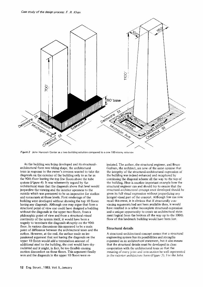
The original programme for the John Hancock Center was not a single tower, but a general requirement of a 1 mf t 2 office building and a 1 m f t 2 apartment building connected together with 800 000 ft 2 of commercial and parking structure. In the urban environment, this would produce diagramatically, a solution as shown in Figure 2 where the commercial and parking structure would be almost 10 storeys high and would create a wall character right at the property line of the site. The two towers, one for the office and the other for the apartment building, would be arranged in some optimal way to create the least disturbance in terms of visual effects. But the relatively small site of 145 000 ft 2 (13 485 m 2) could never resolve the need to have the office building and the apartment building sufficiently far apart. The rather mundane solution
* Deceased (see p. 14), late of Skidmore, Owings & Merrill, 33 West Monroe Street, Chicago, Illinois, USA (Received January 1982)
based on the programme for the project would have also created a sense of congestion at the site and enhanced the canyon character so disliked in many of the urban centres of the industrial world. In search of a better urban solution, the author and his architectural partner, Bruce Graham, began to discuss possible alternate solutions which could offer opportunities to create a better urban environment at the site. Fortunately, at this point the structural concept studied and refined by the author was of considerable help. Two years previously, Mr Mikio Sasaki of Tokyo had come to work on a masters programme in architecture at the liT campus and was hoping to find a structural-architectural solution of high efficiency and economy for a 60 storey building. Mr Myron Goldsmith, Professor of Architecture and the author were Sasaki's advisors, for the thesis project and had jointly proposed the possible use of exterior diagonals in order to make the entire building act as a tube construction. Since sophisticated computer programs were unavailable at that time, the author and Mr Sasaki tested structural models of the project for different loading conditions and generally came to the conclusion that the diagonals would not only act as traditional bracing, but, in fact, help in tying together all the perimeter columns as a part of the tube structure. It became a proven new structural concept waiting to be tested on a real building. The John Hancock Center offered that opportunity.
In discussion with architect Bruce Graham, an exciting possibility became apparent. If the commercial, parking, office and apartment could be all put together in one building, then a large percentage of the site could be left open for ground level use by the public. The impact of the project at the ground level would be much less over- powering and in fact, would contribute to more human interaction so lacking in many of the recent projects. In spite of initial concern about large structural diagonal members crossing through windows in the office, corn-
0141-0296/83/01010-05/$3.00 10 Eng. Struct., 1983, Vol. 5, January © 1983 Butterworth & Co. (Publishers) Ltd

Figure 1 John Hancock Center, Chicago, Illinois, exterior view
Case study of the design process: F. R. Khan
mercial and apartment areas, the design team was finally convinced that the structural-architectural interaction could be taken full advantage of by creating an architectural expression of strength and elegance evoking the spirit of the rational Chicago School of Architecture.
Building shape An efficient floor plan for a commercial or office building should be large, of the order of 25 900 ft z or more, whereas an efficient apartment building floor plan generally should be much smaller. More significantly, an office floor plan needs a lease-span of more than 40 ft which means the width of the building can be more than 160 ft. An apart- ment floor plan on the other hand, cannot effectively use a large distance between the core and exterior wall (lease- span) because every apartment room is expected to have an exterior view and direct open exterior ventilation. Because of this, if there were no structural constraints, the volu- metric form of the building would have been a wide office building that narrows down at the upper floors to a width acceptable for an apartment building. This means that while an office building could be wider than 150 ft at the base, an apartment building cannot be planned with that width, but can have a realistic maximum width of perhaps no more than 125 ft. Schematically this would create an elevation showing stepping off where the apartment floors begin at the upper levels. But the structural system of the trussed tube structure requires a continuity of the four exterior walls throughout the height of the building (Figure 3). This structural requirement initiated a number of studies of the building slowly tapering upwards so that at the first apart- ment floor level the building width is reduced to an acceptable dimension for efficient apartment layout. Dozens of such shapes were studied with the help of a computer program which defined the exterior geometry in each case and computed the individual floor areas as well as the total floor area in the building to match the program requirements. The final shape selected had the base dimension of 160 x 260 ft tapering upwards to 100 x 160 ft at the top floor level. This double tapered truncated pyramid shape was a joint structural-architectural decision satisfying both structural efficiency as well as architectural aesthetics of the form. The structural-architectural inter- action in devising the form and shape of the building is another example of the architect and engineer working closely together as a team rather than the engineer having to solve a preconceived design given to him by the architect.
At the start of the project the most important considera- tion for accepting this diagonally braced truss tube was its efficiency and economy. It had to meet a budget originally established to reflect the competitive traditional construc- tion systems for the traditional two-tower solution. Fortu- nately on the basis of previous experience gained with Mr Sasaki's thesis, 1 the author could realistically predict a maximum of 30 lb of structural steel per ft 2 for this 100 storey building. Normally, a 30 lb per ft 2 budget would be set for a traditional frame building of only 30 to 40 storeys. It was the attraction of a low quantity of steel and the assurance from the author that proper details could be developed to keep the unit price of steel the same as that for a traditional frame building, that helped to make the historic decision to go from a two-tower solution to a 100 storey single tower building.
Eng. Struct., 1983, Vol. 5, January 11
Case study of the design process: F. R. Khan
o ©
base
' j
Figure2 John Hancock Center as a two-building solution compared to a one lOO-storey solution
As the building was being developed and its structural- architectural form was taking shape, the architectural team in response to the owner's concern wanted to take the diagonals on the exterior of the building only to as far as the 90th floor leaving the top few floors above the tube system (Figure 4). It was vehemently argued by the architectural team that the diagonals above that level would jeopardize the viewing and the interior openness to the outside which was presumed to be an imperative for studios and restaurants at those levels. First renderings of the building were developed without showing the top 10 floors having any diagonals. Although one may argue that from a structural point of view one could have designed a building without the diagonals in the upper two floors, from a philosophic point of view and from a structural-visual continuity of the system itself, it would have been a tragedy to terminate the diagonals abruptly on the 90th floor. In various discussions this appeared to be a main point of difference between the architectural team and the author. However, at the end, the author made an im- passioned argument that not having the diagonals on the upper 10 floors would add a tremendous amount of additional steel to the building, the cost would have sky- rocketed and it might, in fact, be too flexible causing motion discomfort on those floors. This argument finally won and the diagonals in the upper 10 floors were re-
instated. The author, the structural engineer, and Bruce Graham, the architect, are now of the same opinion that the integrity of the structural-architectural expression of the building was indeed enhanced and recaptured by continuing the diagonal scheme all the way to the top of the building. Here is another important example how the structural engineer can and should try to ensure that the structural-architectural concept once developed should be given its full visual expression without jeopardizing any integral visual part of the concept. Although few can now recall this event, it is obvious that if structurally con- vincing arguments had not been available then, it would have resulted in a rather incomplete structural expression and a unique opportunity to create an architectural state- ment logical from the bottom all the way up to the 100th floor of this landmark building would have been lost.
Structural details
A structural-architectural concept means that a structural engineering system has its possibilities and strengths expressed as an architectural statement, but it also means that the structural details must be developed in close cooperation with the architectural team so that the meaning of every joint and intersection be well represented in the exterior architecture form (Figure 5). For the John
12 Eng. Struct . , 1983, Vol . 5, January

Case study of the design process: F. R. Khan
Conclus ion
The design process for major architectural projects often does not take advantage of team effort, of all disciplines working together to create the most relevant engineering architectural solution. A priori architectural facades un- related to natural and efficient structural systems are not
O O
I b J -1U ~uJ -Fw
a b Figure 3 (a), Original John Hancock Center structure showing diagonals terminating at 90th floor. (b), Structural truss tube for John Hancock Center
Hancock Center much effort was expended by the author in working very closely with the architectural team to develop the architectural details of cladding and window walls so that the structure was expressed as closely in proportion to the real steel shapes and forms as possible. The major intersections of the diagonals, the horizontal ties and the vertical members were also developed in such a way that the structural form and its function were expressed to accentuate the concept itself (Figure 6). One of the important examples is the cladding material. For a major structural system in steel such as the truss tube concept, it would be philosophically wrong to develop a cladding detail with stone or masonry. Not only would such cladding (enclosure) of the steel members distort their original proportions, but philosophically it would give the impression that the structure itself has a nonmetallic character. Here again considerable discussion resulted in the cladding detail with anodyzed black aluminium which reflected the metallic character of the structure as well as closely retaining the overall proportions of the struc- tural members. In the author's opinion, the structural engineer cannot overlook the visual interest of his structure. Working closely with the architectural team the structural engineer can indeed help developing visual proportions of the building that more closely reflect the real structure hidden behind the fireproofing and the cladding.
Figure 4
Figure 5 members
Diagonal and corner intersection
Major intersection of diagonal, horizontal and vertical
Eng. Struct . , 1983, Vol . 5, January 13

Case study of the design process: F. R. Khan
only a wastage of natural resources but will also have difficulty standing the test of time. The author, in this particular case, has attempted to highlight the structural- architectural team interaction which has resulted in a significant architectural statement based on reason and the laws of nature in such a way that the resulting aesthetics may have a transcendental value and quality far beyond arbitrary forms and expressions that reflect the fashion of the time. Through the case study, the opportunity and responsibility of the engineer to actively participate in the architectural evolution of a building is demonstrated. It is hoped that engineers will not abrogate this sense of
responsibility in the face of today's architeclural ln~ve- lnent, commonly referred to as post-nrodernism.
Acknowledgemen!
This paper is dedicated to Professor Dr Bruno FhtiHimaml on the occasion of his 60th birthday.
Reference
1 Mikio Sasaki, A Tall Office Building:, Illinois Institute of Technology, Chicago, Masters Thesis, June, 1964
The author of the preceding paper, Dr Fazlur Khan, passed away suddenly on 27 March 1982 while travelling in the Middle East.
A world renowned engineer and humanitarian, Dr Khan was born in Dacca, Bangladesh, and received his bachelor of engineering degree from the University of Dacca. After he came to the US, he studied at the University of Illinois, Champaign-Urbana, where he earned degrees of master of structural engineering, master of theoretical and applied mechanics and doctor of structural engineering.
Dr Khan joined the Chicago office of Skidmore, Owings and Merrill in 1955, and became a general partner in charge of structural engineering in 1970. He achieved international distinction for the innovative bundled-tube and long-span structural systems he designed for a wide range of award-winning buildings.
His credits include the world's tallest building, Sears Tower in Chicago: the John Hancock Center, also in Chicago; Spectrum Arena in Philadelphia; the Hai Terminal in Saudi Arabia and the newly opened Hubert H. Humphrey Melrodome in Minneapolis.
Dr Khan was elected a Fellow by the American Society of Civil Engineers. He was a member of the National Academy of Engineering, and chairman of the International Council on Tall Buildings and Urban Habitat. lte lectured civic and educational groups throughout the world, and was honoured by Engineering News Record as Construction 'Man of the Year'.
Beyond his accomplishments as a designer Dr Khan served many years as an Adjunct Professor at the Illinois Institute of Technology where he enhanced his unique talent for integrating the professions of architecture and engineering. He also led a massive relief effort for his native Bangladesh when it was urgently needed.
From the editor's personal relationship with Dr Khan as a junior engineer and colleague, his greatest legacy is perhaps his approach to structural engineering that he shared with so many. Perhaps the preceding paper embodies some of this wisdom. P.L. Gould
14 Eng. Struct., 1983, Vol. 5, January