100 Gigabit Ethernet and Beyond, John D'Ambrosia
8
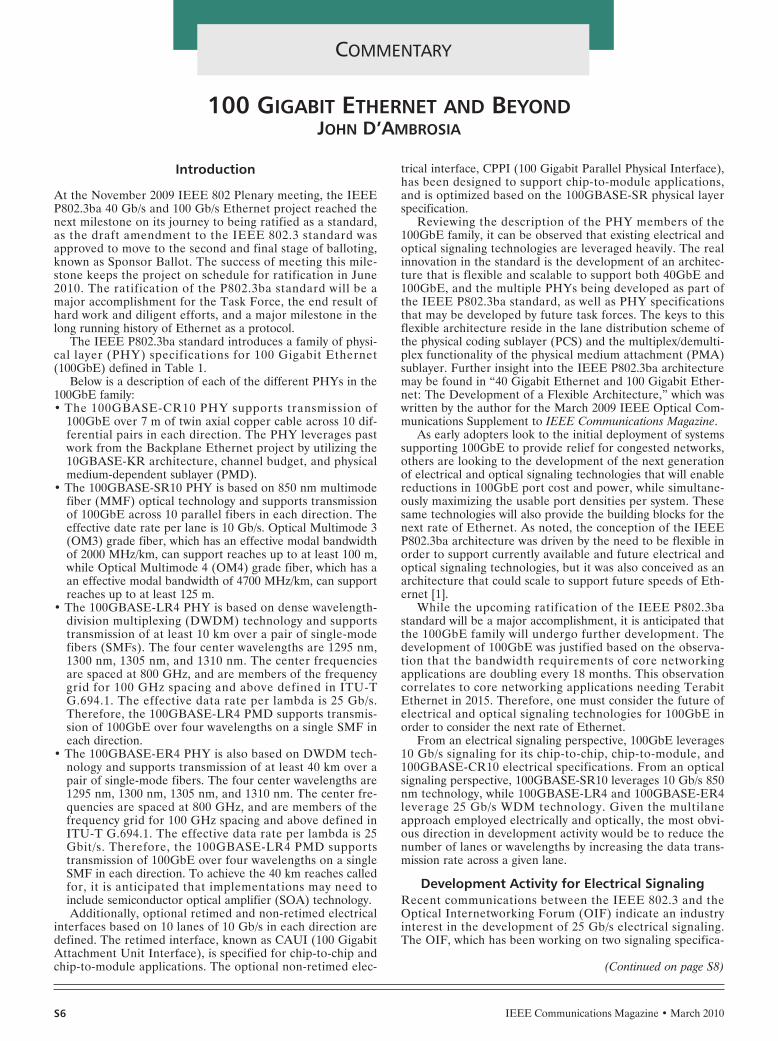
IEEE Communications Magazine • March 2010 COMMENTARY S6 Introduction At the November 2009 IEEE 802 Plenary meeting, the IEEE P802.3ba 40 Gb/s and 100 Gb/s Ethernet project reached the next milestone on its journey to being ratified as a standard, as the draft amendment to the IEEE 802.3 standard was approved to move to the second and final stage of balloting, known as Sponsor Ballot. The success of meeting this mile- stone keeps the project on schedule for ratification in June 2010. The ratification of the P802.3ba standard will be a major accomplishment for the Task Force, the end result of hard work and diligent efforts, and a major milestone in the long running history of Ethernet as a protocol. The IEEE P802.3ba standard introduces a family of physi- cal layer (PHY) specifications for 100 Gigabit Ethernet (100GbE) defined in Table 1. Below is a description of each of the different PHYs in the 100GbE family: • The 100GBASE-CR10 PHY supports transmission of 100GbE over 7 m of twin axial copper cable across 10 dif- ferential pairs in each direction. The PHY leverages past work from the Backplane Ethernet project by utilizing the 10GBASE-KR architecture, channel budget, and physical medium-dependent sublayer (PMD). • The 100GBASE-SR10 PHY is based on 850 nm multimode fiber (MMF) optical technology and supports transmission of 100GbE across 10 parallel fibers in each direction. The effective date rate per lane is 10 Gb/s. Optical Multimode 3 (OM3) grade fiber, which has an effective modal bandwidth of 2000 MHz/km, can support reaches up to at least 100 m, while Optical Multimode 4 (OM4) grade fiber, which has a an effective modal bandwidth of 4700 MHz/km, can support reaches up to at least 125 m. • The 100GBASE-LR4 PHY is based on dense wavelength- division multiplexing (DWDM) technology and supports transmission of at least 10 km over a pair of single-mode fibers (SMFs). The four center wavelengths are 1295 nm, 1300 nm, 1305 nm, and 1310 nm. The center frequencies are spaced at 800 GHz, and are members of the frequency grid for 100 GHz spacing and above defined in ITU-T G.694.1. The effective data rate per lambda is 25 Gb/s. Therefore, the 100GBASE-LR4 PMD supports transmis- sion of 100GbE over four wavelengths on a single SMF in each direction. • The 100GBASE-ER4 PHY is also based on DWDM tech- nology and supports transmission of at least 40 km over a pair of single-mode fibers. The four center wavelengths are 1295 nm, 1300 nm, 1305 nm, and 1310 nm. The center fre- quencies are spaced at 800 GHz, and are members of the frequency grid for 100 GHz spacing and above defined in ITU-T G.694.1. The effective data rate per lambda is 25 Gbit/s. Therefore, the 100GBASE-LR4 PMD supports transmission of 100GbE over four wavelengths on a single SMF in each direction. To achieve the 40 km reaches called for, it is anticipated that implementations may need to include semiconductor optical amplifier (SOA) technology. Additionally, optional retimed and non-retimed electrical interfaces based on 10 lanes of 10 Gb/s in each direction are defined. The retimed interface, known as CAUI (100 Gigabit Attachment Unit Interface), is specified for chip-to-chip and chip-to-module applications. The optional non-retimed elec- trical interface, CPPI (100 Gigabit Parallel Physical Interface), has been designed to support chip-to-module applications, and is optimized based on the 100GBASE-SR physical layer specification. Reviewing the description of the PHY members of the 100GbE family, it can be observed that existing electrical and optical signaling technologies are leveraged heavily. The real innovation in the standard is the development of an architec- ture that is flexible and scalable to support both 40GbE and 100GbE, and the multiple PHYs being developed as part of the IEEE P802.3ba standard, as well as PHY specifications that may be developed by future task forces. The keys to this flexible architecture reside in the lane distribution scheme of the physical coding sublayer (PCS) and the multiplex/demulti- plex functionality of the physical medium attachment (PMA) sublayer. Further insight into the IEEE P802.3ba architecture may be found in “40 Gigabit Ethernet and 100 Gigabit Ether- net: The Development of a Flexible Architecture,” which was written by the author for the March 2009 IEEE Optical Com- munications Supplement to IEEE Communications Magazine. As early adopters look to the initial deployment of systems supporting 100GbE to provide relief for congested networks, others are looking to the development of the next generation of electrical and optical signaling technologies that will enable reductions in 100GbE port cost and power, while simultane- ously maximizing the usable port densities per system. These same technologies will also provide the building blocks for the next rate of Ethernet. As noted, the conception of the IEEE P802.3ba architecture was driven by the need to be flexible in order to support currently available and future electrical and optical signaling technologies, but it was also conceived as an architecture that could scale to support future speeds of Eth- ernet [1]. While the upcoming ratification of the IEEE P802.3ba standard will be a major accomplishment, it is anticipated that the 100GbE family will undergo further development. The development of 100GbE was justified based on the observa- tion that the bandwidth requirements of core networking applications are doubling every 18 months. This observation correlates to core networking applications needing Terabit Ethernet in 2015. Therefore, one must consider the future of electrical and optical signaling technologies for 100GbE in order to consider the next rate of Ethernet. From an electrical signaling perspective, 100GbE leverages 10 Gb/s signaling for its chip-to-chip, chip-to-module, and 100GBASE-CR10 electrical specifications. From an optical signaling perspective, 100GBASE-SR10 leverages 10 Gb/s 850 nm technology, while 100GBASE-LR4 and 100GBASE-ER4 leverage 25 Gb/s WDM technology. Given the multilane approach employed electrically and optically, the most obvi- ous direction in development activity would be to reduce the number of lanes or wavelengths by increasing the data trans- mission rate across a given lane. Development Activity for Electrical Signaling Recent communications between the IEEE 802.3 and the Optical Internetworking Forum (OIF) indicate an industry interest in the development of 25 Gb/s electrical signaling. The OIF, which has been working on two signaling specifica- 100 GIGABIT ETHERNET AND BEYOND JOHN D’AMBROSIA (Continued on page S8)
-
Upload
utopia-media -
Category
Documents
-
view
339 -
download
0
description
This document contains two articles from the IEEE Communication magazine from March 2010.The first is by John D'Ambrosia, Chair of the IEEE 802.3ba committee, and covers the transition from current GigE and 10Gig technology to much faster multi-Gigabit Ethernet network connectivity.D'Ambrosia reminds us that, while the introduction of 40 and 100 Gigabit Ethernet is a big leap, it's only the first step on the path to significantly faster data networks.In the second article, 'The road to 100G deployment', Glenn Wellbrook (Verizon's Director of Backbone Network Design), and Tiejun J. Xia of Verizon Laboratories, give a detailed review of the field trials of 100 GbE at Verizon.
Transcript of 100 Gigabit Ethernet and Beyond, John D'Ambrosia
IEEE Communications Magazine • March 2010
COMMENTARY
S6
Introduction
At the November 2009 IEEE 802 Plenary meeting, the IEEEP802.3ba 40 Gb/s and 100 Gb/s Ethernet project reached thenext milestone on its journey to being ratified as a standard,as the draft amendment to the IEEE 802.3 standard wasapproved to move to the second and final stage of balloting,known as Sponsor Ballot. The success of meeting this mile-stone keeps the project on schedule for ratification in June2010. The ratification of the P802.3ba standard will be amajor accomplishment for the Task Force, the end result ofhard work and diligent efforts, and a major milestone in thelong running history of Ethernet as a protocol.
The IEEE P802.3ba standard introduces a family of physi-cal layer (PHY) specifications for 100 Gigabit Ethernet(100GbE) defined in Table 1.
Below is a description of each of the different PHYs in the100GbE family:• The 100GBASE-CR10 PHY supports transmission of
100GbE over 7 m of twin axial copper cable across 10 dif-ferential pairs in each direction. The PHY leverages pastwork from the Backplane Ethernet project by utilizing the10GBASE-KR architecture, channel budget, and physicalmedium-dependent sublayer (PMD).
• The 100GBASE-SR10 PHY is based on 850 nm multimodefiber (MMF) optical technology and supports transmissionof 100GbE across 10 parallel fibers in each direction. Theeffective date rate per lane is 10 Gb/s. Optical Multimode 3(OM3) grade fiber, which has an effective modal bandwidthof 2000 MHz/km, can support reaches up to at least 100 m,while Optical Multimode 4 (OM4) grade fiber, which has aan effective modal bandwidth of 4700 MHz/km, can supportreaches up to at least 125 m.
• The 100GBASE-LR4 PHY is based on dense wavelength-division multiplexing (DWDM) technology and supportstransmission of at least 10 km over a pair of single-modefibers (SMFs). The four center wavelengths are 1295 nm,1300 nm, 1305 nm, and 1310 nm. The center frequenciesare spaced at 800 GHz, and are members of the frequencygrid for 100 GHz spacing and above defined in ITU-TG.694.1. The effective data rate per lambda is 25 Gb/s.Therefore, the 100GBASE-LR4 PMD supports transmis-sion of 100GbE over four wavelengths on a single SMF ineach direction.
• The 100GBASE-ER4 PHY is also based on DWDM tech-nology and supports transmission of at least 40 km over apair of single-mode fibers. The four center wavelengths are1295 nm, 1300 nm, 1305 nm, and 1310 nm. The center fre-quencies are spaced at 800 GHz, and are members of thefrequency grid for 100 GHz spacing and above defined inITU-T G.694.1. The effective data rate per lambda is 25Gbit/s. Therefore, the 100GBASE-LR4 PMD supportstransmission of 100GbE over four wavelengths on a singleSMF in each direction. To achieve the 40 km reaches calledfor, it is anticipated that implementations may need toinclude semiconductor optical amplifier (SOA) technology.Additionally, optional retimed and non-retimed electrical
interfaces based on 10 lanes of 10 Gb/s in each direction aredefined. The retimed interface, known as CAUI (100 GigabitAttachment Unit Interface), is specified for chip-to-chip andchip-to-module applications. The optional non-retimed elec-
trical interface, CPPI (100 Gigabit Parallel Physical Interface),has been designed to support chip-to-module applications,and is optimized based on the 100GBASE-SR physical layerspecification.
Reviewing the description of the PHY members of the100GbE family, it can be observed that existing electrical andoptical signaling technologies are leveraged heavily. The realinnovation in the standard is the development of an architec-ture that is flexible and scalable to support both 40GbE and100GbE, and the multiple PHYs being developed as part ofthe IEEE P802.3ba standard, as well as PHY specificationsthat may be developed by future task forces. The keys to thisflexible architecture reside in the lane distribution scheme ofthe physical coding sublayer (PCS) and the multiplex/demulti-plex functionality of the physical medium attachment (PMA)sublayer. Further insight into the IEEE P802.3ba architecturemay be found in “40 Gigabit Ethernet and 100 Gigabit Ether-net: The Development of a Flexible Architecture,” which waswritten by the author for the March 2009 IEEE Optical Com-munications Supplement to IEEE Communications Magazine.
As early adopters look to the initial deployment of systemssupporting 100GbE to provide relief for congested networks,others are looking to the development of the next generationof electrical and optical signaling technologies that will enablereductions in 100GbE port cost and power, while simultane-ously maximizing the usable port densities per system. Thesesame technologies will also provide the building blocks for thenext rate of Ethernet. As noted, the conception of the IEEEP802.3ba architecture was driven by the need to be flexible inorder to support currently available and future electrical andoptical signaling technologies, but it was also conceived as anarchitecture that could scale to support future speeds of Eth-ernet [1].
While the upcoming ratification of the IEEE P802.3bastandard will be a major accomplishment, it is anticipated thatthe 100GbE family will undergo further development. Thedevelopment of 100GbE was justified based on the observa-tion that the bandwidth requirements of core networkingapplications are doubling every 18 months. This observationcorrelates to core networking applications needing TerabitEthernet in 2015. Therefore, one must consider the future ofelectrical and optical signaling technologies for 100GbE inorder to consider the next rate of Ethernet.
From an electrical signaling perspective, 100GbE leverages10 Gb/s signaling for its chip-to-chip, chip-to-module, and100GBASE-CR10 electrical specifications. From an opticalsignaling perspective, 100GBASE-SR10 leverages 10 Gb/s 850nm technology, while 100GBASE-LR4 and 100GBASE-ER4leverage 25 Gb/s WDM technology. Given the multilaneapproach employed electrically and optically, the most obvi-ous direction in development activity would be to reduce thenumber of lanes or wavelengths by increasing the data trans-mission rate across a given lane.
Development Activity for Electrical SignalingRecent communications between the IEEE 802.3 and theOptical Internetworking Forum (OIF) indicate an industryinterest in the development of 25 Gb/s electrical signaling.The OIF, which has been working on two signaling specifica-
100 GIGABIT ETHERNET AND BEYONDJOHN D’AMBROSIA
(Continued on page S8)
LYT-COMMENTARY-D'Ambrosia 2/17/10 5:02 PM Page 40

S8
COMMENTARY
IEEE Communications Magazine • March 2010
tions related to 25 Gb/s signaling — CEI-25G-LR (intendedfor backplane applications) and CEI-28G-SR (intended forchip-to-chip and chip-to-module applications) — requestedfeedback from IEEE 802.3. In its response IEEE 802.3 notedthat it was the opinion of participants within IEEE 802.3 thatthe priority for industry development is on a four-lane by 25Gb/s electrical interface that targets chip-to-module applica-tions.
The development of a 4 × 25 Gb/s electrical signalingscheme is most applicable to the 100GBASE-LR4 and100GBASE-ER4 PHYs, as they are based on a 4 × 25 Gb/sper wavelength scheme. Figure 1 illustrates the architecturebeing implemented in first-generation modules. The electricalinterface to the module utilizes CAUI, which is a 10 × 10 Gb/sin each direction. The use of this interface requires the use ofa 10:4 serializer on the transmit side of the module and a 4:10deserializer on the receive side of the module, which will yieldhigher power consumption due to their non-integer ratio [2].Thus, the width of the CAUI interface and the higher power
consumption of the implementation will drive thesize of a module footprint upward. For example,one currently proposed industry standard 100GbEoptical module, the CFP, is specified at 144.75mm deep by 82 mm wide [3]. The width of theCFP is over two times that of the XENPAK mod-ule, which was one of the earlier form factors for10 Gigabit Ethernet (10GbE).
Figure 2 illustrates how the development of aretimed 25 Gb/s electrical interface could beapplied to a next-generation module implementa-tion of 100GBASE-LR4 [4]. Reducing the widthand number of pins of the electrical interface,and reducing the power by eliminating the serial-izer/deserializer in the module could help enable
a smaller module size, potentially toward the width of theXENPAK. This smaller module would enable higher portcounts, thus enabling integration to help drive per port costsdown.
While it is hopeful that cooperation and collaborationbetween IEEE 802.3 and OIF will enable faster implementa-tion of 25 Gb/s electrical signaling, one must also considerthat 10 Gb/s electrical signaling underwent several years ofrefinement. Therefore, it should be expected that the fastestelectrical signaling that will be available for the next speed ofEthernet will most likely be based on 25 Gb/s.
Development Activity for Optical SignalingOptical signaling is being explored in a multitude of areas —from chip-to-chip and board-to-board interconnects to dis-tances that will cover thousands of kilometers. There arethree optical PHYs in the 100GbE family: 100GBASE-SR10,which supports up to 100 m over OM3 fiber; 100GBASE-LR4, which supports up to 10 km over SMF; and 100GBASE-
Table 1. 100GbE physical layer specifications.
Port Type Reach Description
100GBASE-CR10 At least 7 m cu cable 10 × 10 Gb/s
100GBASE-SR10 At least 100 m OM3 MMF(at least 125 m OM4 MMF)
10 × 10 Gb/s(use of Parallel Fiber)
100GBASE-LR4 At least 10 km SMF 4 × 25 Gb/s
100GBASE-ER4 At least 40 km SMF 4 × 25 Gb/s
Figure 1. Generation 1 100GBASE-LR4 implementation concept.
PMA (20:10)
PCS
PMD
100GBASE-LR4
PMA (10:4)
25G
25G
25G
25G
MDMAC
10x10G
Reconciliation
TX_DIS
10:4serializer
REFCLK
TXLANE9 EMLTXLANE8TXLANE7TXLANE6TXLANE5TXLANE4TXLANE3TXLANE2TXLANE1TXLANE0
4:1WDMMUX
MD EML
MDSMF
CAUI(10x10Gb/s)
CGMII
MDI
EML
MD EML
TEC
25G
25G
25G
25G
Micro-controller
TIA
4:10de-
serializer
RXLANE9 PINRXLANE8RXLANE7RXLANE6RXLANE5RXLANE4RXLANE3RXLANE2RXLANE1RXLANE0
RX_RCLK
RX_LOS
1:4WDMDe-
MUX
TIA PIN
TIASMF
PIN
TIA
Firmware I/O
Hardware I/O
PIN
Medium
(Continued from page S6)
(Continued on page S10)
LYT-COMMENTARY-D'Ambrosia 2/17/10 5:02 PM Page 42

ER4, which supports up to 40 km over SMF. While the select-ed PHYs for 100GbE were described earlier, it is worthwhileto consider other proposals that were considered for therespective PHYs, in order to assess the potential for futuredevelopment efforts.
Potential development efforts for the 100GBASE-SR fami-ly were suggested during the proposal selection process of the
project. While the IEEE P802.3ba Task Force selected a solu-tion based on parallel multimode fibers (MMFs), there were anumber of discussions regarding the development of a solu-tion that could be delivered across a duplex MMF solution.One proposal suggested using a WDM-based architecture,similar to the one adopted for 100GBASE-LR4 shown in Fig.1, that utilized 4 wavelengths on a 7 nm channel spacing
COMMENTARY
S10 IEEE Communications Magazine • March 2010
Figure 2. Generation 2 100GBASE-LR4 implementation concept.
MDI
4x25G
PMD
PMA (4:4)
PMA (20:4)
PCS
Reconciliation
MAC25G
25G
25G
25G
LD DML
4:1WDMMUX
LD DML
LDSMF
DML
LD
CDR
CDR
CDR
CDRCGMI
4x25G
TXLANE3
REFCLK
TX_DIS
TXLANE2
TXLANE1
TXLANE0 DML
TEC
25G
25G
25G
25G
TIA PIN
1:4WDMDe-
MUX
TIA PIN
TIASMF
PIN
TIA
CDR
CDR
CDR
CDR
RXLANE3
RXLANE2
RXLANE1
RXLANE0
RX_RCLK
RX_LOS
PIN
MediumMicro-controller
Firmware I/O
Hardware I/O
100GBASE-LR4
Figure 3. Potential concept for 400GbE.
DML
13 SMF
16:1LANWDM Mux
CDRTX15
REFCLK
LD
. . .. . . . . .
25G
DMLCDRTX1 LD25G
DML
TEC
CDRTX0 LD25G
13
PIN
13 SMF
400GBASE-LR16CEI-28G
SOA
1:16 LAN WDM DeMux
CDR RX15 TIA
. . . . . . . . .
25G
PIN CDR RX1 TIA 25G
PIN CDR RX0 TIA 25G
13
(Continued from page S8)
(Continued on page S12)
LYT-COMMENTARY-D'Ambrosia 2/19/10 12:17 PM Page 44

IEEE Communications Magazine • March 2010
COMMENTARY
around 850 nm at 25 Gb/s per wavelength [5]. Also, duringthe proposal selection process for the 40GBASE-SR PHY,one presentation suggested that with OM4 fiber 40 Gb/s serialrates could be achieved [6].
For 100GbE over SMF the Task Force quickly movedtoward the adopted WDM approach, as no competing pro-posals were provided. It was realized, however, from earlywork during the Study Group phase of the project that workexploring alternate modulation schemes, such as differentialquadrature phase shift keying (DQPSK), was underway, espe-cially for long-haul transmission. Industry consensus on a sin-gle modulation scheme has not yet been achieved; therefore,it is unclear whether such an optical signaling technologywould be ready to be utilized for the next speed of Ethernet.So, while a serial or single wavelength solution was notadopted, the knowledge of exploratory work in this spacehelped influence the desire to develop an architecture thatwould ultimately be able to utilize such a PMD solution whenit became available.
At the time of writing this column, IEEE 802.3 has formeda new study group that will examine the need for the develop-ment of a 40 Gb/s Ethernet SMF is optimized for client appli-cations in the carrier environment. Given that carrierdeployment of 40G technology started in 2004 with modulesdeployed that could support either OTU3 or OC-768, whichare both based on non-return-to-zero (NRZ) technology [7], itis anticipated that an Ethernet solution for this space would
need to coexist with these protocols, and hence will also be aserial solution.
At this time it appears that the 100GbE family of opticalPHYs could grow, but it would seem that the obvious candi-date would be a new PHY focused on delivering 100GbEacross a duplex MMF solution using some sort of WDMsolution based on 25 Gb/s per optical wavelength. At thistime it is uncertain when a new project targeting adding aserial or single-wavelength PHY to the 100GbE familymight occur.
Looking AheadThe introduction of 100GbE will drive the development of thenext generation of electrical and optical signaling technologiesto drive the reduction in cost and power per 100GbE port andmaximize the usable port densities per system.
As noted earlier, however, based on the observation thatbandwidth requirements for core networking applications aredoubling approximately every 18 months, core networkingapplications are forecasted to need Terabit Ethernet in 2015.Thus, discussions regarding the next speed of Ethernet havealready begun.
The IEEE P802.3ba architecture has been developed to bea flexible and scalable architecture. The future developmentefforts in electrical and optical signaling will be the gatingitems for developing the next speed. The next generation ofelectrical signaling will target interfaces based on 25 Gb/s. Foroptical transmission over multi-mode fiber two possible pathsexist — development of a 4 × 25 Gb/s per optical wavelength
S12
(Continued from page S10)
LYT-COMMENTARY-D'Ambrosia 2/17/10 5:02 PM Page 46
PHY over duplex fiber for 100GbE or the development of aserial 40 Gb/s solution for 40GbE. For optical transmissionover single-mode fiber the path forward is unclear — a singlelambda solution using a modulation technique, such asDQPSK, is a possible answer, but the actual timing for stan-dardization is unclear.
The debate regarding the next speed of Ethernet hasalso been influenced by the decision of the IEEE P802.3baTask Force to break with the tradition of only doing 10xleaps in speed. This has fueled speculation that the nextleap in speed for Ethernet will be 400 Gb/s, which couldleverage electrical and optical technologies being devel-oped for the next generation of 100GbE. For example, oneproposal for 400GbE suggested a solution based on a 16-lane interface based on 25 Gb/s electrical signaling and 16optical wavelengths [8]. By leveraging these technologies,the costs associated with developing such a solution couldbe minimized. Conversely, based on the potential technolo-gies that will be developed over the next few years in sup-port of 100GbE, it is not clear how Terabit Ethernet wouldeven be accomplished. For example, the electrical interfaceby itself would be 40 lanes wide in each direction with eachlane operating at 25 Gb/s.
ConclusionsDuring the course of the study group phase of the IEEEP802.3ba project, a number of individuals with data centerbackgrounds got up and expressed interest in 100GbE,based on the aggregation of Gigabit Ethernet servers incomputer clusters. Meanwhile, network engineers in datacenters look ahead to deployment of server clusters builton 10GbE-based servers, with cross-sectional bandwidthsof fabrics reaching into multi-terabits of capacity. Similarneeds have also been discussed by those in the carriercommunity and Internet exchanges. So while technicalfeasibility, which is one of the five criteria on which newprojects are judged within the IEEE, is a key issue, anoth-er is broad market potential. As noted, the forecastedneed in 2015 is for Terabit Ethernet. Therefore, while400GbE is technically feasible, the question is will therebe customer interest in it? This will be the key questionthat will be discussed within the industry in the monthsahead. The next rates for networks will ultimately be dis-cussed and decided within standards bodies such as theIEEE and ITU-T.
The discussion regarding the next rate of Ethernet, whichwill be decided by the next IEEE 802.3 Higher Speed StudyGroup, has begun!
REFERENCES[1] J. D’Ambrosia, “40 Gigabit Ethernet and 100 Gigabit Ethernet: The
Development of a Flexible Architecture,” IEEE Commun. Mag., Mar.2009.
[2] Cole et al., “100GBE Optical LAN Technologies,” IEEE Applications &Practice, Dec. 2007.
[3] CFP MSA Draft1.0, http://www.cfp-msa.org/Documents/CFP-MSA-DRAFT-rev-1-0.pdf, Mar. 23, 2009.
[4] Cole et al., “100GBE Optical LAN Technologies,” IEEE Applications &Practice, Dec. 2007.
[5] Kropp et al., “40GBit/s and 100GBit/s Transmission over OM3 DuplexFiber, IEEE P802.3ba May 2008 Interim Meeting, http://www.ieee802.org/3/ba/public/may08/kropp_01_0508.pdf
[6] Kropp et al., “1×40 GBit/s and 4×25 GBit/s Transmission at 850nm onMultimode Fiber, IEEE 802, Mar. 2008 Plenary Meeting,http://www.ieee802.org/3/ba/public/mar08/kropp_01_0308.pdf
[7] 40GE SMF PMD Call for Interest, IEEE Nov 2009 802 Plenary,http://www.ieee802.org/3/40GSMF/public/nov09/40GSMF_CFI_1109.zip
[8] Cole, “Life Beyond IEEE P802.3ba,” Ethernet Alliance — TechnologyExploration Forum, Sept. 2009.
[9] Lee, “Life Beyond 100G,” OIDA, 18th Annual Forum, Dec. 2009.
IEEE Communications Magazine • March 20010 S13
COMMENTARY
LYT-COMMENTARY-D'Ambrosia 2/17/10 5:02 PM Page 47

IEEE Communications Magazine • March 2010
COMMENTARY
S14
Abstract
This article contains a detailed review of the field trials andeventual deployment of 100 Gb/s at Verizon including testsetup, measured results, and industry first deployment data.
New data-centric applications continue to drive doubledigit traffic growth rates [1, 2]. To increase capacity of thetransport network, several approaches have been studied. Ofthese methods, three stand out: using higher data rates, wideramplifier bandwidth, and/or narrower channel spacing.Because higher data rates can be supported on existing sys-tems, this is the most likely first step. To that end, Verizonconducted three separate field trials using 100 Gb/s per wave-length. The intent is to establish performance expectationsand push the industry toward similar solutions so that theentire ecosystem of component, subsystem, and system suppli-ers work together to bring products to market quicker and atbetter cost points. While the amplifier has always been anintegral part of any line system, it becomes even more impor-tant when advanced modulation formats and very-high-endsignal processing are used to mitigate fiber impairments likepolarization mode dispersion (PMD) and chromatic disper-sion (CD). In this regime system reach is dictated primarily byoptical signal-to-noise ratio (OSNR) tolerance. Granted, verysophisticated forward error correction (FEC) algorithms arebeing developed, but the amplifier is a key building block toachieve ultra-long-haul (ULH) distances.
100 Gb/s technology development is a major breakthroughfor the next-generation transport network. In the foreseeablefuture, Internet traffic is expected to grow at a fast pacebecause of bandwidth-hungry services, such as video services,large-scale data storage and mirroring, increased social net-working, real-time gaming, and other services taking advantageof broadband communications. In the past several years U.S.broadband services have grown about 40 percent annually [1].In the next several years global Internet traffic will likely main-tain a similar, if not higher, growth rate [2]. Figure 1 showsglobal IP traffic predictions up to 2012. In 2012 global IP traf-fic is expected to exceed 40 exabytes (1018 bytes) per month,of which consumer IP traffic is the largest portion. Increased
Internet traffic growth is driving large carriers to prepare toprovide enough bandwidth to meet market demand.
While carriers and service providers feel the urgency todevelop more powerful networks, equipment suppliers alsofeel that urgency. In the optical transport equipment commu-nity technology development is chasing the pace of bandwidthdemand growth. In terms of channel data rates 100 Gb/s is thenext step. Most recently, 100 Gb/s development has gainedhuge momentum [3–21]. Figure 2 shows the trajectory of 100Gb/s dense wavelength-division multiplexing (DWDM) evolu-tion based on published papers from major optical communi-cation conferences. If transport capability is defined ascapacity times distance in a unit of Pb/s-km, 100 Gb/s capabili-ty quickly grows from below 1 Pb/s-km to near 100 Pb/s-km inless than three years. This is a result of tremendous industrialinvestment. This result proves the 100 Gb/s optical channel isable to match, if not exceed, the performance of the tradition-al 10G channel but with 10 times the capacity for each fiber.
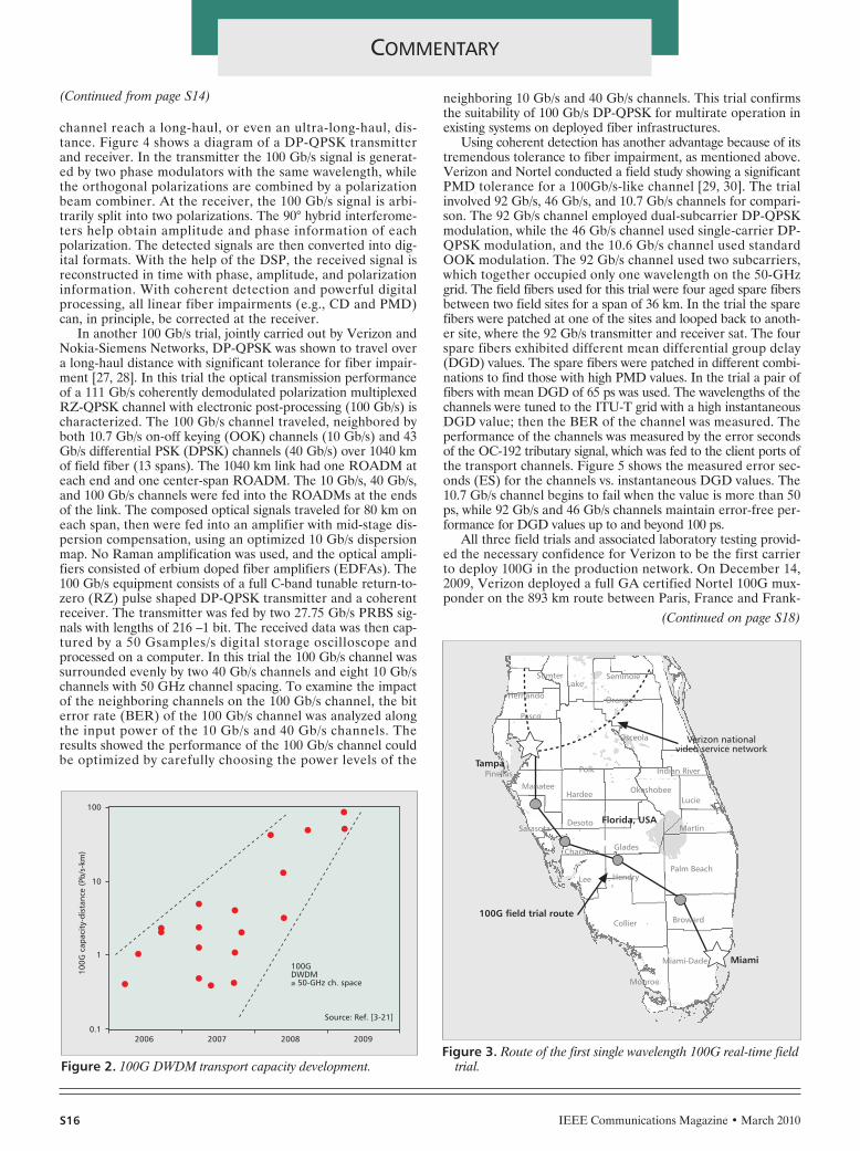
In 2007 the first real-time traffic carried by a single-wavelength100 Gb/s channel over a deployed long-haul system was accom-plished [22–25]. This trial demonstrated that 100 Gb/s channelscan be overlaid onto an existing in-service DWDM infrastructure,which would provide notable economic advantages for carriers. Ina joint field trial with Verizon and Alcatel-Lucent, a 107 Gb/schannel carrying live video traffic traveled over a 504 km in-serviceDWDM route between Tampa and Miami, Florida. The 100 Gb/schannel propagated together with nine commercial 10 Gb/s chan-nels. This long-haul system is a 50-GHz-spaced Raman-pumpedDWDM system. The 100 Gb/s channel was added at the TampaROADM as an alien wavelength and dropped at a ROADM inMiami. Figure 3 shows the field configuration for the trial.
The modulation format used in this 100 Gb/s trial wasreturn-to-zero differential quadrature phase shift keying (RZ-DQPSK) at 53.5 Gbaud with all the necessary real-time signalprocessing functions. At the transmitter, an OC192 signal,which contained live HDTV traffic in a GbE channel, wastapped optically from Verizon’s national video service networkand fed to the client port of the 100 Gb/s equipment. The 107Gb/s RZ-DQPSK signal was then fed into a reconfigurableoptical add/drop multiplexer (ROADM) and transmitted over504 km. Then the signal was dropped using a differentROADM and fed into the 100 Gb/s receiver. The original OC-192 signal containing the live HDTV video traffic was thenreconstructed in the receiver. The OC-192 was fed into anADM to re-create the GbE channel, which was then fed into avideo test set to extract different HDTV channels for display.During the trial, neither synchronous optical network (SONET)errors nor video signal defects were observed on the 100 Gb/swavelength, and all 10 Gb/s channels remained error-free.
Many modulation formats have been proposed for long-distance 100 Gb/s transmission. Taking advantage of matureDWDM technology and balancing capacity and reach dis-tance, dual polarization quadrature phase shift keying (DP-QPSK) with coherent detection is gaining more attention overother modulation formats for 100 Gb/s transport equipment[26]. The baud rate of DP-QPSK 100 Gb/s channel is a quar-ter of the data rate, so the channel easily fits into a 50-GHz-spaced channel plan. Coherent detection with ultra-high-speedanalog-to-digital conversion (ADC) and digital signal process-ing (DSP) improve the requirement for OSNR and help the
THE ROAD TO 100G DEPLOYMENTGLENN WELLBROCK AND TIEJUN J. XIA
Figure 1. Global IP traffic growth.
20060
Glo
bal I
P tr
affi
c (E
B/m
onth
)
10
20
30
40
50
2007
Source: Ref. [2]
2008 2009 2010 2011 2012
Mobile IPBusiness IPConsumer IP
(Continued on page S16)
LYT-COMMENTARY-Wellbrock 2/16/10 4:21 PM Page 48
S16 IEEE Communications Magazine • March 2010
COMMENTARY
channel reach a long-haul, or even an ultra-long-haul, dis-tance. Figure 4 shows a diagram of a DP-QPSK transmitterand receiver. In the transmitter the 100 Gb/s signal is generat-ed by two phase modulators with the same wavelength, whilethe orthogonal polarizations are combined by a polarizationbeam combiner. At the receiver, the 100 Gb/s signal is arbi-trarily split into two polarizations. The 90° hybrid interferome-ters help obtain amplitude and phase information of eachpolarization. The detected signals are then converted into dig-ital formats. With the help of the DSP, the received signal isreconstructed in time with phase, amplitude, and polarizationinformation. With coherent detection and powerful digitalprocessing, all linear fiber impairments (e.g., CD and PMD)can, in principle, be corrected at the receiver.
In another 100 Gb/s trial, jointly carried out by Verizon andNokia-Siemens Networks, DP-QPSK was shown to travel overa long-haul distance with significant tolerance for fiber impair-ment [27, 28]. In this trial the optical transmission performanceof a 111 Gb/s coherently demodulated polarization multiplexedRZ-QPSK channel with electronic post-processing (100 Gb/s) ischaracterized. The 100 Gb/s channel traveled, neighbored byboth 10.7 Gb/s on-off keying (OOK) channels (10 Gb/s) and 43Gb/s differential PSK (DPSK) channels (40 Gb/s) over 1040 kmof field fiber (13 spans). The 1040 km link had one ROADM ateach end and one center-span ROADM. The 10 Gb/s, 40 Gb/s,and 100 Gb/s channels were fed into the ROADMs at the endsof the link. The composed optical signals traveled for 80 km oneach span, then were fed into an amplifier with mid-stage dis-persion compensation, using an optimized 10 Gb/s dispersionmap. No Raman amplification was used, and the optical ampli-fiers consisted of erbium doped fiber amplifiers (EDFAs). The100 Gb/s equipment consists of a full C-band tunable return-to-zero (RZ) pulse shaped DP-QPSK transmitter and a coherentreceiver. The transmitter was fed by two 27.75 Gb/s PRBS sig-nals with lengths of 216 –1 bit. The received data was then cap-tured by a 50 Gsamples/s digital storage oscilloscope andprocessed on a computer. In this trial the 100 Gb/s channel wassurrounded evenly by two 40 Gb/s channels and eight 10 Gb/schannels with 50 GHz channel spacing. To examine the impactof the neighboring channels on the 100 Gb/s channel, the biterror rate (BER) of the 100 Gb/s channel was analyzed alongthe input power of the 10 Gb/s and 40 Gb/s channels. Theresults showed the performance of the 100 Gb/s channel couldbe optimized by carefully choosing the power levels of the
neighboring 10 Gb/s and 40 Gb/s channels. This trial confirmsthe suitability of 100 Gb/s DP-QPSK for multirate operation inexisting systems on deployed fiber infrastructures.
Using coherent detection has another advantage because of itstremendous tolerance to fiber impairment, as mentioned above.Verizon and Nortel conducted a field study showing a significantPMD tolerance for a 100Gb/s-like channel [29, 30]. The trialinvolved 92 Gb/s, 46 Gb/s, and 10.7 Gb/s channels for compari-son. The 92 Gb/s channel employed dual-subcarrier DP-QPSKmodulation, while the 46 Gb/s channel used single-carrier DP-QPSK modulation, and the 10.6 Gb/s channel used standardOOK modulation. The 92 Gb/s channel used two subcarriers,which together occupied only one wavelength on the 50-GHzgrid. The field fibers used for this trial were four aged spare fibersbetween two field sites for a span of 36 km. In the trial the sparefibers were patched at one of the sites and looped back to anoth-er site, where the 92 Gb/s transmitter and receiver sat. The fourspare fibers exhibited different mean differential group delay(DGD) values. The spare fibers were patched in different combi-nations to find those with high PMD values. In the trial a pair offibers with mean DGD of 65 ps was used. The wavelengths of thechannels were tuned to the ITU-T grid with a high instantaneousDGD value; then the BER of the channel was measured. Theperformance of the channels was measured by the error secondsof the OC-192 tributary signal, which was fed to the client ports ofthe transport channels. Figure 5 shows the measured error sec-onds (ES) for the channels vs. instantaneous DGD values. The10.7 Gb/s channel begins to fail when the value is more than 50ps, while 92 Gb/s and 46 Gb/s channels maintain error-free per-formance for DGD values up to and beyond 100 ps.
All three field trials and associated laboratory testing provid-ed the necessary confidence for Verizon to be the first carrierto deploy 100G in the production network. On December 14,2009, Verizon deployed a full GA certified Nortel 100G mux-ponder on the 893 km route between Paris, France and Frank-
Figure 2. 100G DWDM transport capacity development.
100GDWDM≥ 50-GHz ch. space
Source: Ref. [3-21]
20060.1
100G
cap
acit
y-di
stan
ce (
Pb/s
-km
)
1
10
100
2007 2008 2009
Figure 3. Route of the first single wavelength 100G real-time fieldtrial.
HendryLee
Charlotte Glades
Martin
Lucie
Indian River
Okeshobee
Florida, USADesotoSarasota
ManateeHardee
Polk
Osceola
Orange
SeminoleSumterLake
Hernando
Pasco
Monroe
Miami-Dade
Collier Broward
Miami
Palm Beach
100G field trial route
TampaPinellas
Verizon nationalvideo service network
(Continued from page S14)
(Continued on page S18)
LYT-COMMENTARY-Wellbrock 2/16/10 4:21 PM Page 50

furt, Germany. No changes were made to the existing Nortelline system that also carries many 10G circuits between thesetwo locations. Live traffic was placed on the 100G channel, andother routes are being considered for turn-up in 2010 [31].
REFERENCES[1] S. Elby, “Bandwidth Flexibility and High Availability,” presentation at
Service Provider Summit, OFC/NFOEC 2009.[2] Cisco white paper, “Cisco Visual Networking Index — Forecast and
Methodology, 2007–2012,” 2008.[3] G. Raybon et al., “10 × 107 Gb/s Electronically Multiplexed and Optically
Equalized NRZ Transmission over 400 km,” OFC/NFOEC 2006, PDP32.[4] P. J. Winzer et al., “10 × 107 Gb/s Electronically Multiplexed NRZ Trans-
mission at 0.7 bits/s/Hz over 1000 km Non-Zero Dispersion Fiber,” ECOC2006, Tu1.5.1.
[5] P. J. Winzer et al., “2000-km WDM transmission of 10 × 107 Gb/s RZ-DQPSK,” ECOC 2006, Th4.1.3.
[6] A. Sano et al., “14-Tb/s (140 × 111 Gb/s PDM/WDM) CSRZ-DQPSK Trans-mission over 160 km Using 7-THz Bandwidth Extended L-band EDFAs,”ECOC 2006, Th4.1.1.
[7] H. Masuda et al., “20.4-Tb/s (204 × 111 Gb/s) Transmission over 240 km UsingBandwidth- Maximized Hybrid Raman/EDFAs,” OFC/NFOEC 2007, PDP20.
[8] C. R. Fludger et al., “10 × 111 Gb/s, 50 GHz Spaced, POLMUX-RZ-DQPSKTransmission over 2375 km Emp loying Coherent Equalisation,”OFC/NFOEC 2007, PDP22.
[9] K. Schuh et al., “1 Tbit/s (10×107 Gb/s ETDM) NRZ Transmission over480km SSMF,” OFC/NFOEC 2007, PDP23.
[10] P. J. Winzer et al., “10 × 107 Gb/s NRZ-DQPSK Transmission at 1.0b/s/Hz over 12 × 100 km Including 6 Optical Routing Nodes,”OFC/NFOEC 2007, PDP24.
[11] K. Schuh et al., “8 × 10⁷ Gb/s Serial Binary NRZ/VSB Transmission over480 km SSMF with 1 bit/s/Hz Spectral Efficiency and without OpticalEqualizer,” ECOC 2007, Mo2.3.1.
[12] A. Sano et al., “30 × 100- Gb/s All-Optical OFDM Transmission over1300 km SMF with 10 ROADM Nodes,” ECOC 2007, PD 1.7.
[13] K. Schuh et al., “8 Tbit/s (80×107 Gb/s) DWDM ASK-NRZ VSB Transmis-sion over 510 km NZDSF with 1bit/s/Hz Spectral Efficiency,” ECOC 2007,PD 1.8.
[14] C. Sethumadhavan et al., “ Hybrid 107- Gb/s Polarization-MultiplexedDQPSK and 42.7 Gb/s DQPSK Transmission at 1.4-bits/s/Hz Spectral Effi-ciency over 1280 km of SSMF and 4 Bandwidth-Managed ROADMs,”ECOC 2007, PD 1.9.
[15] X. Zhou et al., “2Tb/s (20×107 Gb/s) RZ-DQPSK Straight-Line Transmis-sion over 1005 km of SSMF without Raman Amplification,” OFC/NFOEC2008, OMQ3.
[16] G. Charlet et al., “Transmission of 16.4Tbit/s Capacity over 2,550kmUsing PDM QPSK Modulation Format and Coherent Receiver,”OFC/NFOEC 2008, PDP3.
[17] J. Yu et al., “20×112 Gb/s, 50GHz spaced, PolMux-RZ-QPSK Straight-Line Transmission over 1540km of SSMF Employing Digital CoherentDetection and Pure EDFA Amplification,” ECOC 2008, Th.2.A.2.
[18] J. Renaudier et al., “Experimental Analysis of 100 Gb/s Coherent PDM-QPSK Long-Haul Transmission under Constraints of Typical TerrestrialNetworks,” ECOC 2008, Th.2.A.3.
[19] A. Sano et al., “13.4-Tb/s (134 × 111 Gb/s/ch) No-Guard-Interval Coher-ent OFDM Transmission over 3,600 km of SMF with 19-ps averagePMD,” ECOC 2008, Th.3.E.1.
[20] H. Masuda et al., “13.5-Tb/s (135 × 111 Gb/s/ch) No-Guard-IntervalCoherent OFDM Transmission over 6,248 km Using SNR Maximized Sec-ond-Order DRA in the Extended L-Band,” OFC/NFOEC 2009, PDPB5.
[21] G. Charlet et al., “72×100 Gb/s Transmission over Transoceanic Dis-tance, Using Large Effective Area Fiber, Hybrid Raman-Erbium Amplifi-cation and Coherent Detection,” OFC/NFOEC 2009, PDPB6.
[22] Verizon News Release, “Verizon Successfully Completes Industry’s FirstField Trial of 100 Gb/s Optical Network Transmission,” Nov. 19, 2007.
[23] T. J. Xia et al., “Transmission of 107 Gb/s DQPSK over Verizon 504-kmCommercial LambdaXtreme Transport System,” OFC/NFOEC 2008, NMC2.
[24] G. Wellbrock et al., “Field Trial of 107- Gb/s Channel Carrying LiveVideo Traffic over 504 km In-Service DWDM Route,” 21st IEEE/LEOSAnnual Meeting, WH1, Newport Beach, USA, Nov. 2008.
[25] P. J. Winzer et al., “100- Gb/s DQPSK Transmission: from LaboratoryExperiments to Field Trials,” JLT, Vol 26, No 20, 3388(2008).
[26] OIF, “100G Ultra Long Haul DWDM Framework Document,” June 30,2009.
[27] Verizon News Release, “Verizon and Nokia Siemens Networks Set NewRecord for 100 Gb/s Optical Transmission,” Sept. 25, 2008.
[28] T. J. Xia et al., “Multi-Rate (111- Gb/s, 2×43- Gb/s, and 8×10.7 Gb/s)Transmission at 50-GHz Channel Spacing over 1040-km Field-DeployedFiber,” ECOC 2008, Th.2.E.2.
[29] Verizon News Release, “Verizon Confirms Quality of 100G Transmis-sion,” Oct. 6, 2008.
[30] T. J. Xia et al., “92 Gb/s Field Trial with Ultra-High PMD Tolerance of107-ps DGD,” OFC/NFOEC 2009, NThB3.
[31] Verizon News Release, “Verizon Deploys Commercial 100G Ultra-Long-Haul Optical System on Portion of Its Core European Network,” Dec.14, 2009.
COMMENTARY
S18 IEEE Communications Magazine • March 2010
Figure 5. Measured error seconds of the 92Gb/s, 46Gb/s and10.7Gb/s channels.
Instantaneous DGD (ps)0
20%
Erro
r se
cond
s (E
S)
0%
40%
60%
80%
100%
30 60 90 120
92 Gb/s46 Gb/s10.7 Gb/s
Figure 4. DP-QPSK transmitter and receiver proposed for 100 Gb/s transmission.
ADC and DSP
Laser
Laser
π/2
Datagenerator
Phase modulator
DP-QPSK transmitter DP-QPSK receiver
90º hybrid
π/2
(Continued from page S16)
LYT-COMMENTARY-Wellbrock 2/16/10 4:21 PM Page 52