10” WET TILE/STONE SAW - Harbor Freight...
23
10” WET TILE/STONE SAW 2.4 HP With Stand Model 95492 ASSEMBLY AND OPERATING INSTRUCTIONS Copyright 2006 by Harbor Freight Tools ® . All rights reserved. No portion of this manual or any artwork contained herein may be reproduced in any shape or form without the express written consent of Harbor Freight Tools. For technical questions, please call 1-800-444-3353. ® © TO PREVENT SERIOUS INJURY, READ AND UNDERSTAND ALL WARNINGS AND INSTRUCTIONS BEFORE USE. Due to continuing improvements, actual product may differ slightly from the product described herein. 3491 Mission Oaks Blvd., Camarillo, CA 93011 Visit our Web site at: http://www.harborfreight.com
Transcript of 10” WET TILE/STONE SAW - Harbor Freight...

10” WET TILE/STONE SAW2.4 HP With Stand
Model 95492
ASSEMBLY AND OPERATING INSTRUCTIONS
Copyright 2006 by Harbor Freight Tools®. All rights reserved. No portion of thismanual or any artwork contained herein may be reproduced in any shape or form
without the express written consent of Harbor Freight Tools.For technical questions, please call 1-800-444-3353.
®
©
TO PREVENT SERIOUS INJURY,READ AND UNDERSTAND ALL WARNINGS
AND INSTRUCTIONS BEFORE USE.
Due to continuing improvements, actual product may differ slightly from the product described herein.
3491 Mission Oaks Blvd., Camarillo, CA 93011Visit our Web site at: http://www.harborfreight.com

PRODUCT SPECIFICATIONS
SAVE THIS MANUALYou will need this manual for the safety warnings and precautions, assembly,operating, inspection, maintenance and cleaning procedures, parts list and as-sembly diagram. Keep your invoice with this manual. Write the invoice numberon the inside of the front cover. Keep this manual and invoice in a safe and dryplace for future reference.
WARNING!READ AND UNDERSTAND ALL INSTRUCTIONS
Failure to follow all instructions listed below may result inelectric shock, fire, and/or serious injury.
SAVE THESE INSTRUCTIONS
1. Keep your work area clean and well lit. Cluttered benches and dark areasinvite accidents.
2. Do not operate the Stone/Tile Saw in explosive atmospheres, such as inthe presence of flammable liquids, gases, or dust. Power equipment createssparks which may ignite the dust or fumes.
3. Keep bystanders, children, and visitors away while operating power equip-ment. Distractions can cause you to lose control. Protect others in the work
SKU 95492 For technical questions, please call 1-800-444-3353 PAGE 2
WORK AREA
GENERAL SAFETY RULES
Item Description Electrical Requirements (Motor)
120 VAC / 60 Hz / 916 Watts / 3550 RPM Amperage Draw: 7.64 Amps Power Cord Type: 14 AWG x 3C SJTW Cord / 9’ Long Power Plug Type: 3-Prong / Grounded
Electrical Requirements (Water Pump)
120 VAC / 60 Hz / 0.23 Amps Power Cord Type: 18 AWG x 3C
Pump Type & Flow Capacity Submersible Fountain Pump with Flow Adjustment / 246 Gallons Per Hour Required Saw Blade Size (Included)
10” Diameter / Continuous Rim Diamond Blade 5/8” Spindle Hole / Minimum 3550 RPM
Maximum Cutting Depth 2” @ 90° / 1-9/16” @ 45° Maximum Cutting Length 40” Saw Bevel Capacity 0° to 45° in 2.5° Increments (Left Tilt Only) Miter Gauge Capacity 0° to 45° in 1° Increments (Right Angles Only) Rip Fence Scale 0” to 8-1/4” in 1/8” Increments (0mm to 21mm in 2mm Increments) Fence Type Fixed Spindle Size 5/8” Diameter Coolant Basin Capacity 4 Gallons Work Table Dimensions 24-1/4” Long x 6-1/2” Wide (Qty. 2) / 24-1/4” Long x 9” Wide (Qty. 2) Overall Dimensions 55” Long x 21-9/16” Wide x 66-15/16” High Net Weight 153 Pounds

ELECTRICAL SAFETY
1. Grounded tools must be plugged into an outlet properly installed andgrounded in accordance with all codes and ordinances. Never remove thegrounding prong or modify the plug in any way. Do not use any adapterplugs. Check with a qualified electrician if you are in doubt as to whetherthe outlet is properly grounded. If the tools should electrically malfunction orbreak down, grounding provides a low resistance path to carry electricity awayfrom the user.
2. Avoid body contact with grounded surfaces such as pipes, radiators,ranges, and refrigerators. There is an increased risk of electric shock if yourbody is grounded.
3. Do not expose power tools to rain or wet conditions. Water entering powerequipment will increase the risk of electric shock.
4. Do not abuse the Power Cord. Never use the Power Cord to carry the toolsor pull the Plug from an outlet. Keep the Power Cord away from heat, oil,sharp edges, or moving parts. Replace damaged Power Cords immedi-ately. Damaged Power Cords increase the risk of electric shock.
PERSONAL SAFETY
1. Stay alert. Watch what you are doing, and use common sense when oper-ating the Stone/Tile Saw. Do not use the tool while tired or under the influ-ence of drugs, alcohol, or medication. A moment of inattention while operat-ing power tools may result in serious personal injury.
2. Dress properly. Do not wear loose clothing or jewelry. Contain long hair.Keep your hair, clothing, and gloves away from moving parts. Looseclothes, jewelry, or long hair can be caught in moving parts.
3. Use the right product for the job. Do not attempt to force small equipment todo the work of larger industrial equipment. There are certain applications forwhich this product was designed. It will do the job better and safer at the rateand capacity for which it was designed. Do not modify this product, and do notuse this product for a purpose for which it was not designed.
SKU 95492 For technical questions, please call 1-800-444-3353 PAGE 3
area from debris such as chips and sparks. Provide barriers or shields asneeded. Children and visitors should never be in the work area.
4. Avoid accidental starting. Be sure the Power Switch is off before plugging

in. Plugging in power equipment with the Power Switch on, invites accidents.
5. Remove adjusting keys or wrenches before turning the power tool on. Awrench or a key that is left attached to a rotating part of the Stone/Tile Saw mayresult in personal injury.
6. Do not overreach. Keep proper footing and balance at all times. Properfooting and balance enables better control of the Stone/Tile Saw in unexpectedsituations.
7. Use safety equipment. Always wear ANSI approved safety impacteye goggles. Dust mask or respirator, and hearing protection must beused for appropriate conditions.
TOOL USE AND CARE
1. Do not force the Stone/Tile Saw. Use the correct tool for your application.The correct tool will do the job better and safer at the rate for which it is de-signed.
2. Do not use the Stone/Tile Saw if the Power Switch does not turn it on or off.Any tool that cannot be controlled with the Power Switch is dangerous and mustbe replaced.
3. Disconnect the Power Cord Plug from the power source before making anyadjustments, changing accessories, or storing the Stone/Tile Saw. Suchpreventive safety measures reduce the risk of starting the tool accidentally.
4. Store idle tools and equipment out of reach of children and other untrainedpersons. Tools and equipment are dangerous in the hands of untrained users.
5. Maintain this product with care. Keep the Stone/Tile Saw clean and inproper working order. Properly maintained tools and equipment are easier tocontrol. Do not use damaged tools and equipment. Tag damaged tools andequipment “Do not use” until repaired.
SKU 95492 For technical questions, please call 1-800-444-3353 PAGE 4
7. Use only accessories that are recommended by the manufacturer for yourmodel. Accessories that may be suitable for one product may become hazard-ous when used on another product.
6. Check for misalignment or binding of moving parts, breakage of parts, andany other condition that may affect the Stone/Tile Saw’s operation. If dam-aged, have the tool serviced before using. Many accidents are caused bypoorly maintained tools.

SPECIFIC SAFETY RULES
1. Maintain labels and nameplates on the Stone/Tile Saw. These carry impor-tant information. If unreadable or missing, contact Harbor Freight Tools for areplacement.
2. Avoid unintentional starting. Make sure you are prepared to begin work beforeturning on the Stone/Tile Saw.
3. Do not force the Stone/Tile Saw. This tool will do the work better and safer atthe speed and capacity for which it was designed.
4. WARNING! To reduce the risk of electric shock, connect only to anoutlet provided with a ground fault circuit interrupting device.
5. This Stone/Tile Saw is designed for use only with Diamond Saw Bladeswith a 10” diameter, 5/8” round spindle hole, and rated at 3550 RPM orgreater.
6. WARNING! Keep hands and fingers away from the cutting area andSaw Blade. Use a “push stick” (not included) when necessary.
SKU 95492 For technical questions, please call 1-800-444-3353 PAGE 5
8. Never leave the Stone/Tile Saw unattended when it is plugged into anelectrical outlet. Always unplug the unit from its electrical outlet before leaving.
SERVICE
1. Tool service must be performed only by qualified repair personnel. Serviceor maintenance performed by unqualified personnel could result in a risk of injury.
2. When servicing a tool, use only identical replacement parts. Followinstructions in the “Inspection, Maintenance, And Cleaning” section of thismanual. Use of unauthorized parts or failure to follow maintenance instructionsmay create a risk of electric shock or injury.
7. Make sure the Stone/Tile Saw is located on a dry, flat, level, sturdy surfacecapable of supporting the weight of the unit, accessories, and workpieces.
9. Industrial applications must follow OSHA guidelines.
10. Never stand on the Stone/Tile Saw. Serious injury could result if the unit istipped.
11. Always unplug the Stone/Tile Saw from its power supply source before

performing any inspection, maintenance, or cleaning procedures.
12. Keep all guards in place and in proper working order.
13. Check Blade Guard for proper forward/backward movement before eachuse. Do not operate the Stone/Tile Saw if the Blade Guard does not movefreely. Make sure the Blade Guard moves freely and does not touch the SawBlade or any other part of the Saw, in all angles and depths of cut.
14. Do not handle the Power Switch with wet hands.
15. Use the Stone/Tile Saw only for cutting ceramic tile, quarry tile, terra cotta,and slate with a maximum thickness of 2” (if cutting at a 90 degree angle)or 1-9/16” (if cutting at a 45 degree angle).
16. Do not use the Stone/Tile Saw for cutting metals or curves. This may causethe Saw Blade to break and/or reduce its service life.
17. Keep all electrical connections dry and off the ground.
18. Always arrange a “drip loop” in the Power Cord connecting the Stone/TileSaw to a 120 volt, grounded, electrical outlet. A drip loop is that part of thePower Cord below the level of the outlet, or the connector if an extension cord isused, to prevent water traveling along the Power Cord and coming in contact withthe outlet. If the Power Plug or electrical outlet does get wet, do not unplug thePower Cord. Disconnect the fuse or circuit breaker that supplies power to theStone/Tile Saw. Then, unplug and examine for presence of water in the outlet.(See Figure A.)
FIGURE A
POWER CORD/PLUG(12)
“DRIP LOOP”
120 VOLTGFCI
ELECTRICALOUTLET
19. Use cold water only. Never use hot water. Using hot water can damage thePump’s seals.
20. Never run the Stone/Tile Saw without a water supply. Running the unit with-out a water supply will cause irreparable damage to the Pump.
SKU 95492 For technical questions, please call 1-800-444-3353 PAGE 6

21. Make sure the water supply used for the Stone/Tile Saw is not dirty, sandy,and does not contain any corrosive chemical products.
22. Make sure to change the water when necessary while in use and rinse outthe Tank after every use. Excessively dirty water will clog the pump.
23. Always keep the water level at the recommended level. Fill the Tank withenough water so that the Pump is about 3/4 completely submerged, but not somuch water that the Tank overflows.
24. Avoid splashing water on the Motor, Power Switch, Power Cord, orany other electrical component. Make sure to stand on a dry, insulatedsurface such as a rubber mat while using the Stone/Tile Saw.
25. To avoid accidental injury, always wear heavy duty work gloves whenchanging the Saw Blade.
26. Before using the Stone/Tile Saw, make sure the Saw Blade is properlymounted on the Saw Spindle. Make sure the Saw Blade is balanced, and isnot cracked or bent.
27. The Saw Blade will become hot when cutting. Allow the Saw Blade to com-pletely cool before handling.
28. Allow the Saw Blade to spin up to full speed before feeding it into aworkpiece. When turning off the Stone/Tile Saw, allow the Saw Blade to spindown and stop on its own. Do not press against the Saw Blade to stop it.
29. Turn off the Stone/Tile Saw and allow the Saw Blade to stop on its own ifthe Saw Blade is to be backed out of an uncompleted cut.
32. For your safety: In extreme working conditions, sensors in the Stone/Tile Sawwill automatically switch off the Motor to prevent overheating. In this event, turnthe Power Switch to its “OFF” position. Wait five minutes or until the Motor hascooled. Making sure your hands are dry, depress the Circuit Breaker. Then, turnthe Power Switch to its “ON” position to resume cutting. NEVER attempt todisable the Circuit Breaker.
31. When cutting a large workpiece, make sure its entire length is properlysupported. If necessary, use a roller stand (not included) with largerworkpieces.
30. Never attempt to remove material stuck in the moving parts of the Stone/Tile Saw while it is plugged in and running.
SKU 95492 For technical questions, please call 1-800-444-3353 PAGE 7

33. Never attempt to cut more than one tile at a time.
34. Never attempt to cut freehand. Make sure the tile to be cut is pressed firmlyagainst the Rip Fence.
35. Never cut pieces too small to be held securely against the Rip Fence with-out leaving enough space for the hands to be a safe distance from the SawBlade.
36. Make sure the tile to be cut off has sufficient room to move sideways. Fail-ure to do so may result in the tile binding against the Saw Blade.
37. Make sure the Table and surrounding area are clear with the exception ofthe tile to be cut.
39. WARNING! Some dust created by power sanding, sawing, grinding, drilling,and other construction activities, contain chemicals known (to the State of Cali-fornia) to cause cancer, birth defects or other reproductive harm. Some ex-amples of these chemicals are: lead from lead-based paints, crystalline silicafrom bricks and cement or other masonry products, arsenic and chromium fromchemically treated lumber. Your risk from these exposures varies, depending onhow often you do this type of work. To reduce your exposure to these chemicals:work in a well ventilated area, and work with approved safety equipment, such asthose dust masks that are specially designed to filter out microscopic particles.(California Health & Safety Code 25249.5, et seq.)
40. WARNING! People with pacemakers should consult their physician(s)before using this product. Operation of electrical equipment in close proximity toa heart pacemaker could cause interference or failure of the pacemaker.
41. WARNING! The warnings and cautions discussed in this manual cannotcover all possible conditions and situations that may occur. It must be under-stood by the operator that common sense and caution are factors which cannotbe built into this product, but must be supplied by the operator.
SAVE THESE INSTRUCTIONS
38. Use the right tool for the job. Do not attempt to force a small tool or attach-ment to do the work of a larger industrial tool. There are certain applications forwhich this tool was designed. It will do the job better and more safely at the ratefor which it was intended. Do not modify this tool, and do not use this tool for apurpose for which it was not intended.
SKU 95492 For technical questions, please call 1-800-444-3353 PAGE 8

SKU 95492 For technical questions, please call 1-800-444-3353 PAGE 9
GROUNDING
WARNING!Improperly connecting the grounding wire can result in the risk of electric
shock. Check with a qualified electrician if you are in doubt as to whether theoutlet is properly grounded. Do not modify the power cord plug provided with
the tool. Never remove the grounding prong from the plug. Do not use thetool if the power cord or plug is damaged. If damaged, have it repaired bya service facility before use. If the plug will not fit the outlet, have a proper
outlet installed by a qualified electrician.
GROUNDED TOOLS: TOOLS WITH THREE PRONG PLUGS
1. Tools marked with “Grounding Required” have a three wire cord and three pronggrounding plug. The plug must be connected to a properly grounded outlet. Ifthe tool should electrically malfunction or break down, grounding provides a lowresistance path to carry electricity away from the user, reducing the risk of elec-tric shock. (See Figure B.)
2. The grounding prong in the plug is connected through the green wire inside thecord to the grounding system in the tool. The green wire in the cord must be theonly wire connected to the tool’s grounding system and must never be attachedto an electrically “live” terminal. (See Figure B.)
3. Your tool must be plugged into an appropriate outlet, properly installed andgrounded in accordance with all codes and ordinances. The plug and outletshould look like those in the following illustration. (See Figure B.)
THIS PRODUCTUSES A
3-PRONG PLUG
120 VOLT,GROUNDED,
ELECTRICAL OUTLET
FIGURE B
SYMBOLOGY
FIGURE C

SKU 95492 For technical questions, please call 1-800-444-3353 PAGE 10
When unpacking, check to make sure all the parts shown on the Parts List on page 21are included. If any parts are missing or broken, please call Harbor Freight Tools at thenumber shown on the cover of this manual as soon as possible.
UNPACKING
ASSEMBLY INSTRUCTIONS
IMPORTANT:For your protection, make sure you understand how thePower Switch (10C) and Circuit Breaker (10D) operate
prior to beginning the assembly process.
3. CAUTION! Always make sure the Power Switch (10C) of the Stone/TileSaw is in its “OFF” position and the unit is unplugged from its electrical outletprior to performing any inspection, maintenance, or cleaning procedures.(See Figure D.)
The Power Switch And Circuit Breaker:
1. To start the Stone/Tile Saw, press the “ON” button of the Power Switch (10C).To stop the Saw, press the “OFF” button of the Power Switch. (See Figure D.)
2. The Motor (7) is equipped with a Circuit Breaker (10D). Should the Motor be-come overloaded, too hot, or the current too high, the Circuit Breaker will auto-matically shut off the Motor. In this case, press the “OFF” button of the PowerSwitch (10C). Wait several minutes until the Motor has cooled down. Then pressthe “ON” button of the Power Switch to resume cutting. (See Figure D.)
POWER SWITCH(10C)
CIRCUIT BREAKER(10D)
“POWER ON”INDICATOR LIGHT
(10E)
FIGURE D
To Set Up The Stone/Tile Saw:
1. With assistance, move the Stone/Tile Saw to the desired work area.

SKU 95492 For technical questions, please call 1-800-444-3353 PAGE 11
2. Make sure the location is free of debris, dry, level, and allows sufficient work-space. (See Figure E.)
3. Pull out the Locking Bracket (45) located at the rear of the machine.(See Figure F.)
FIGURE E
FIGURE F
LOCKING BRACKET(45)
4. With assistance, lift the left side of the Stone/Tile Saw to unfold its first set ofLegs (39A). Make sure the Legs are fully extended. Then, tighten the twoButterfly Knobs (28) to secure the Legs in position. (See Figure G.)
FIGURE G
LEFTLEGS(39A) RIGHT
LEGS(37A) FIGURE H
5. Lift the right side of the Stone/Tile Saw to unfold its second set of Legs (37A).Make sure the Legs are fully extended. Then, tighten the two Butterfly Knobs(28) to secure the Legs in position. (See Figure H.)
BUTTERFLY KNOB(28)

6. Insert the two mounting slots of the Extension Table (26) onto the two mountingpegs located at the rear of the Water Tray (34). Pull out the Support Stand (27A)fully. Then secure the Support Stand in place by tightening the Butterfly Knob(28). NOTE: The Support Stand may be lengthened or shortened by using theSupport Stand Adjuster (27B). (See Figure I.)
EXTENSION TABLE(26)
BUTTERFLY KNOB(28)
SUPPORT STAND ADJUSTER (27B) FIGURE I
To Attach The Handle:
1. Align the two mounting holes in the Handle (9) with the two threaded mountingholes in the Motor Bracket (8). Secure the Handle to the Motor Bracket, usingtwo Screws (46). (See Figure J.)
SCREW(46)
HANDLE(9)
FIGURE J
To Fill And Drain The Water Tray:
1. Lift the Front Table (21) (as shown in Figure K) and fill the water tray. Make sureto use clean, cold water. Do not add chemicals or detergents to the water.(See Figure K, next page.)
2. Make sure the water level is always between the “MAXIMUM” and “MINIMUM”level as indicated inside the Water Tray (34). This is necessary so that the Saw
SKU 95492 For technical questions, please call 1-800-444-3353 PAGE 12
MOUNTING PEGS NOT SHOWN

SKU 95492 For technical questions, please call 1-800-444-3353 PAGE 13
WATER TRAY(34)
FRONTTABLE
(21)
3. When the Stone/Tile Saw is not in use, the water should be drained and theWater Tray (34) thoroughly cleaned. To do so, remove the Table (21). Place asuitable container directly under the Drain Plug (30A) of the Water Tray (34).Unscrew and remove the Drain Plug and allow the water to completely drain intothe container. (See Figures K and L.)
FIGURE K
DRAIN PLUG(30A)
Blade (4) continuously rotates in the water to keep it cool when in use.(See Figure K.)
FIGURE L
4. After cleaning the Water Tray (34), replace the Drain Plug (30A). Then replacethe Front Table (21), making sure the Pin in the Table fits into the Pinhole locatedon the Water Tray. (See Figures M and N.)
FRONTTABLE
(21)
WATER TRAY(34)
PIN&
PINHOLE
FIGURE M FIGURE N
OPERATING INSTRUCTIONS
To Make A Straight Cut:
1. Check to make sure the Water Tray (34) is filled with the proper amount of clean,cold water. (See Figure K.)
2. The Blade Guard (1) and Saw Blade (4) assemblies are locked in place duringshipment. To unlock, loosen the Butterfly Knob (28) located at either end of the
FRONTTABLE
(21)
WATER TRAY (34)

machine. When not in use, keep the Blade Guard (1) and Saw Blade (4) assem-blies locked in place to prevent them rolling back and forth along the Slide Rail(19). (See Figure O.)
2. Make sure the Power Switch (10C) is in its “OFF” position. Then, plug the PowerCord/Plug (12) into the nearest 120 volt, GFCI electrical outlet, making sure toform a “drip loop” in the Power Cord. (See Figure P.)
BUTTERFLY KNOB(28)
FIGURE O FIGURE P
POWER CORD&
PLUG(12)
“DRIP LOOP”
3. Loosen the Butterfly Knob (24B) on the Rip/Miter Guide (25) and position theGuide so that it is in a straight line, with the zero aligned with the notch. Thisindicates “no angle” or a “straight cut”. The Rip/Miter Guide will be at a 90 de-gree angle to the Position Scale (23). Make sure to tighten the Butterfly Knob tosecure the Rip/Miter Guide in position. (See Figure Q.)
4. Slide the Rip/Miter Guide (25) against the tile to be cut, and lock the Rip/MiterGuide by tightening the Butterfly Knob (24B). (See Figure Q.)
5. Make sure the Saw Blade (4) does not contact any part of the tile. Then, turnthe Power Switch (10C) to its “ON” position to start the Stone/Tile Saw.(See Figure D.)
6. Keep the tile firmly against the Position Scale (23) and Rip/Miter Guide (25).Using the Handle (9), slowly and smoothly pull the Blade Guard (1) and SawBlade (4) assemblies towards you to begin cutting. Do not attempt to force theMotor (7) to cut too quickly. (See Figure Q.)
BUTTERFLY KNOB(24B)
BUTTERFLY KNOB(24B)
RIP/MITERGUIDE
(25)
POSITIONSCALE
(23)
FIGURE Q
SKU 95492 For technical questions, please call 1-800-444-3353 PAGE 14
TILE

To Make A Miter Cut:
1. Loosen the Butterfly Knob (24B) and position the Rip/Miter Guide (25) so thatthe desired angle of cut (from 0 degrees to 45 degrees) is lined up with thenotch. Then, retighten the Butterfly Knob. (See Figure R.)
2. Align the tile with the Rip/Miter Guide (25) and hold the tile firmly against theGuide. (See Figure R.)
7. When finished cutting, turn the Power Switch (10C) to its “OFF” position. Then,unplug the Power Cord/Plug (12) from its electrical outlet.(See Figures D and P.)
3. Using the Handle (9), slowly and smoothly pull the Blade Guard (1) and SawBlade (4) assemblies towards you to begin cutting. Do not attempt to force theMotor (7) to cut too quickly. (See Figure R.)
RIP/MITER GUIDE(25)
BUTTERFLY KNOB(24B)
TILE
FIGURE R
4. When finished cutting, turn the Power Switch (10C) to its “OFF” position. Then,unplug the Power Cord/Plug (12) from its electrical outlet.(See Figures D and P.)
To Make A Bevel Cut:
1. Loosen the Knob (14) on both the Left Rail Stand (16) and Right Rail Stand (20).Then, tilt the Slide Rail (19) to the desired bevel angle (from 0 degrees to 45degrees). Make sure to line up the bevel angle number markings on each RailStand. (See Figure S, next page.)
2. Once the bevel angle is set on each Rail Stand (16, 20), retighten the Knob (14)on each Rail Stand. (See Figure S, next page.)
3. Align the tile with the Rip/Miter Guide (25) and Position Scale (23) and hold thetile firmly against the Guide and Scale. (See Figure S, next page.)
SKU 95492 For technical questions, please call 1-800-444-3353 PAGE 15

4. Using the Handle (9), slowly and smoothly pull the Blade Guard (1) and SawBlade (4) assemblies towards you to begin cutting. Do not attempt to force theMotor (7) to cut too quickly. (See Figure S.)
5. When finished cutting, turn the Power Switch (10C) to its “OFF” position. Then,unplug the Power Cord/Plug (12) from its electrical outlet.(See Figures D and S.)
LEFT RAIL STAND (16)RIGHT
RAIL STAND(20)
KNOB (14)
SLIDE RAIL (19)
FIGURE S
To Move The Stone/Tile Saw:
1. To move the Stone/Tile Saw, make sure the Power Switch (10C) is in its “OFF”position. Then, unplug the Power Cord/Plug (12) from its electrical outlet.(See Figures D and S.)
2. Drain all water from the Water Tray (34), and completely fold the machine.(See Figure T.)
3. Lay the Stone/Tile Saw on a dry, level surface. Then loosen the Butterfly Knob(35) to pull out the Wheel (39B) assembly. (See Figure T.) Retighten the Knob.
4. Loosen the Butterfly Knob (35) and pull out the T-Handle (33) from under theWater Tray (34). Then, retighten the Butterfly Knob. (See Figure T.)
SKU 95492 For technical questions, please call 1-800-444-3353 PAGE 16
RIGHTRAIL STAND
(20) POWERCORD/PLUG
(12)
FIGURE T
SKU 95492 For technical questions, please call 1-800-444-3353 PAGE 17
INSPECTION, MAINTENANCE, AND CLEANING
1. CAUTION! Always make sure the Power Switch of the Stone/Tile Saw is inits “OFF” position and the unit is unplugged from its electrical outlet prior toperforming any inspection, maintenance, or cleaning procedures.
2. Before each use: Inspect the general condition of the Stone/Tile Saw. Checkfor misalignment or binding of moving parts, cracked or broken parts, damagedelectrical wiring, and any other condition that may affect its safe operation. Ifabnormal noise or vibration occurs, have the problem corrected before furtheruse. Do not use damaged equipment.
3. To clean the Stone/Tile Saw:
A. Use only a clean cloth and mild detergent. Then dry the machine as much as possible. Do not immerse any electrical part of the unit in liquid. Do not use solvents.
B. Keep the ventilation slots of the Motor (7) clean to prevent overheating of the Motor.
C. Drain and clean the Water Tray (34) after each use. Then dry.
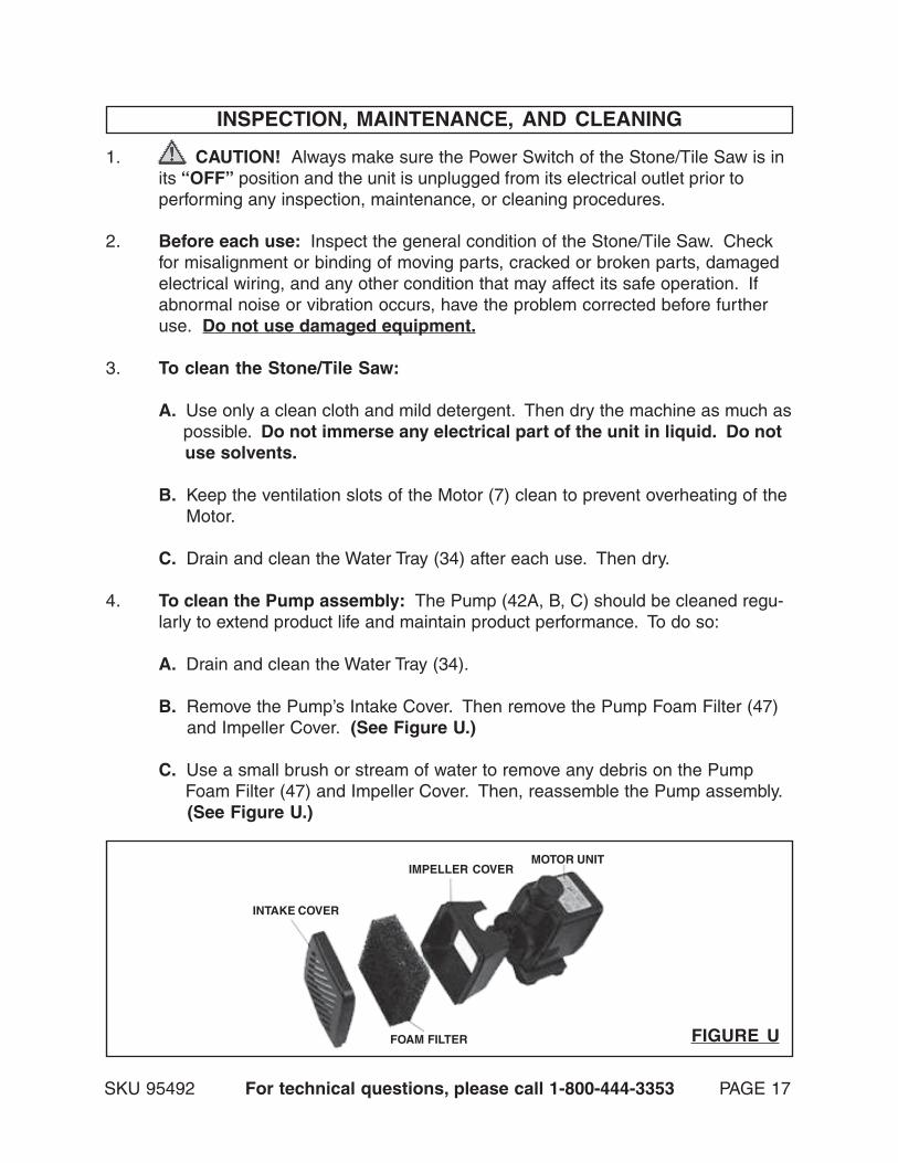
4. To clean the Pump assembly: The Pump (42A, B, C) should be cleaned regu-larly to extend product life and maintain product performance. To do so:
A. Drain and clean the Water Tray (34).
B. Remove the Pump’s Intake Cover. Then remove the Pump Foam Filter (47) and Impeller Cover. (See Figure U.)
C. Use a small brush or stream of water to remove any debris on the Pump Foam Filter (47) and Impeller Cover. Then, reassemble the Pump assembly. (See Figure U.)
FIGURE U
INTAKE COVER
FOAM FILTER
IMPELLER COVERMOTOR UNIT

5. To replace the Pump assembly: Should it become necessary to replace adamaged or malfunctioning Pump (42A, B, C) assembly, follow the Steps below:
A. Drain and clean the Water Tray (34).
B. The Pump Connecting Box (31) is located at the end of the Water Tray (34). Unscrew and remove the Screw on the Connecting Box Cover (32). Then, remove the Connecting Box Cover. (See Figure V.)
C. Unscrew and remove the Screw on the Pump Cable Lock. Then, pull out the Pump Plug from the Connecting Box. (See Figure V.)
D. Disconnect the Plug of the Pump (42A, B, C) from its Socket. Then, unscrew and remove the Nut connecting the Pump with the Pipe. (See Figure V.)
E. Replace the old Pump (42A, B, C) with a new Pump by reversing the above Steps. (See Figure V.)
FIGURE V
SKU 95492 For technical questions, please call 1-800-444-3353 PAGE 18
6. To Replace The Saw Blade: The Saw Blade (4) should be checked beforeeach use of the Stone/Tile Saw. A dull or damaged Saw Blade is potentiallydangerous to the operator and will result in a poor quality stone/tile cut. Toreplace the Saw Blade:
A. To disconnect the water supply, press the blue ring and pull out the Water
CONNECTINGBOX
COVER(32)
PUMPSOCKET
PUMPPLUG
PUMPCABLELOCK
PIPE
NUT
PUMP(42A,B,C)

SKU 95492 For technical questions, please call 1-800-444-3353 PAGE 19
7. CAUTION! All maintenance, service, or repairs not mentioned in thismanual must only be performed by a qualified service technician.
Supply Tube (40) from the Inlet Connection on the Blade Guard (1). (See Figure W.)
B. Remove the Blade Guard (1) by removing the two Screws. (See Figure W.)
C. Use the Small Hex Wrench (43) provided to hold the Motor (7) Shaft in place. Then use the Large Hex Wrench (44) provided to unscrew and remove the Blade Securing Nut (2). Then, remove the Outside Flange (3). (See Figure W.)
D. Remove the old Saw Blade (4). Then install the new Saw Blade by reversing the Steps above.
E. IMPORTANT: The proper size and type of Saw Blade (4) for this Stone/Tile Saw is as follows: 10” diameter, continuous rim diamond blade, 5/8” spindle hole, rated at a minimum 3550 RPM. (See Figure W.)
FIGURE W
BLUERING
BLADEGUARD
(1)
WATERSUPPLY
TUBE(40)
BLADEGUARD
(1)
SMALLHEX
WRENCH(43)
LARGEHEX
WRENCH(44)
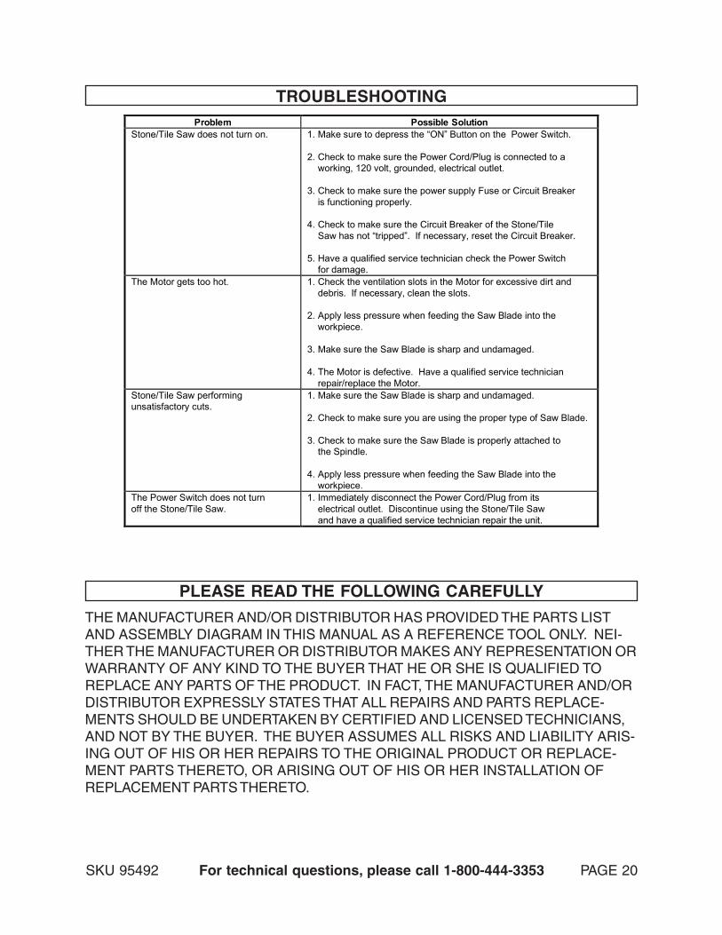
TROUBLESHOOTINGProblem Possible Solution
Stone/Tile Saw does not turn on. 1. Make sure to depress the “ON” Button on the Power Switch. 2. Check to make sure the Power Cord/Plug is connected to a working, 120 volt, grounded, electrical outlet. 3. Check to make sure the power supply Fuse or Circuit Breaker is functioning properly. 4. Check to make sure the Circuit Breaker of the Stone/Tile Saw has not “tripped”. If necessary, reset the Circuit Breaker. 5. Have a qualified service technician check the Power Switch for damage.
The Motor gets too hot. 1. Check the ventilation slots in the Motor for excessive dirt and debris. If necessary, clean the slots. 2. Apply less pressure when feeding the Saw Blade into the workpiece. 3. Make sure the Saw Blade is sharp and undamaged. 4. The Motor is defective. Have a qualified service technician repair/replace the Motor.
Stone/Tile Saw performing unsatisfactory cuts.
1. Make sure the Saw Blade is sharp and undamaged. 2. Check to make sure you are using the proper type of Saw Blade. 3. Check to make sure the Saw Blade is properly attached to the Spindle. 4. Apply less pressure when feeding the Saw Blade into the workpiece.
The Power Switch does not turn off the Stone/Tile Saw.
1. Immediately disconnect the Power Cord/Plug from its electrical outlet. Discontinue using the Stone/Tile Saw and have a qualified service technician repair the unit.
PLEASE READ THE FOLLOWING CAREFULLY
THE MANUFACTURER AND/OR DISTRIBUTOR HAS PROVIDED THE PARTS LISTAND ASSEMBLY DIAGRAM IN THIS MANUAL AS A REFERENCE TOOL ONLY. NEI-THER THE MANUFACTURER OR DISTRIBUTOR MAKES ANY REPRESENTATION ORWARRANTY OF ANY KIND TO THE BUYER THAT HE OR SHE IS QUALIFIED TOREPLACE ANY PARTS OF THE PRODUCT. IN FACT, THE MANUFACTURER AND/ORDISTRIBUTOR EXPRESSLY STATES THAT ALL REPAIRS AND PARTS REPLACE-MENTS SHOULD BE UNDERTAKEN BY CERTIFIED AND LICENSED TECHNICIANS,AND NOT BY THE BUYER. THE BUYER ASSUMES ALL RISKS AND LIABILITY ARIS-ING OUT OF HIS OR HER REPAIRS TO THE ORIGINAL PRODUCT OR REPLACE-MENT PARTS THERETO, OR ARISING OUT OF HIS OR HER INSTALLATION OFREPLACEMENT PARTS THERETO.
SKU 95492 For technical questions, please call 1-800-444-3353 PAGE 20

PARTS LIST
SKU 95492 For technical questions, please call 1-800-444-3353 PAGE 21
NOTE:Some parts are listed and shown for illustration purposes only,
and are not available individually as replacement parts.
Part # Description Part # Description 1 Blade Guard 24A Angle Cutting Guide 2 Blade Securing Nut 24B Butterfly Knob 3 Outside Flange 25 Rip/Miter Guide 4 Saw Blade 26 Extension Table 5 Inside Flange 27A Support Stand 6 Motor Cover 27B Supporting Stand Adjuster 7 Motor 28 Butterfly Knob 8 Motor Bracket 29 Rail Stand Support 9 Handle 30A, 30B, 30C, 30D, 30E Drain Plug 10A Switch Base 31 Connecting Box 10B Capacitor 32 Connecting Box Cover 10C Power Switch 33 T-Handle 10D Circuit Breaker 34 Water Tray 10E Indicator Light 35 Butterfly Knob 10F Switch Cover 36 Standing Frame Wheel 10G Cable Lock 37A Right Leg 11 Bearing Bracket 37B Adjuster 12 Power Cord/Plug 38 Foot Pad 13 Adjusting Bearing Sheath 39A Left Leg 14 Knob 39B Wheel 15 Water Tube Holder 40 Water Supply Tube 16 Left Rail Stand 41 Pump Cable 17 Spring Washer 42A, 42B, 42C Pump 18 Water Tube Cover 43 Small Hex Wrench 19 Slide Rail 44 Large Hex Wrench 20 Right Rail Stand 45 Locking Bracket 21 Front Table 46 Screw 22 Rear Table 46 Screw 23 Position Scale 47 Pump Foam Filter

ASSEMBLY DIAGRAM
NO
TE:
Som
e pa
rts
are
liste
d an
d sh
own
for i
llust
ratio
n pu
rpos
es o
nly,
and
are
not a
vaila
ble
indi
vidu
ally
as
repl
acem
ent p
arts
.
SKU 95492 For technical questions, please call 1-800-444-3353 PAGE 22
Lock
ing
Bra
cket
(45)
not
sho
wn.
PU
MP
FO
AM
FIL
TE
R (4
7) N
OT
SH
OW
N.

IMPORTANT WARRANTY INFORMATION
SKU 95492 For technical questions, please call 1-800-444-3353 PAGE 23
Harbor Freight Tools Co. makes every effort to assure that its products meet high quality and durability standards, and warrants to the original purchaser for a period of ninety days from date of purchase that the motor, the belts (if so equipped), and the blades (if so equipped) are free of defects in materials and workmanship. Harbor Freight Tools also warrants to the original purchaser, for a period of one year from date of purchase, that all other parts and components of the product are free from defects in materials and workmanship. This warranty does not apply to damage due directly or indirectly to misuse, abuse, negligence or accidents; repairs or alterations outside our facilities; or to lack of maintenance. We shall in no event be liable for death, injuries to persons or property, or for incidental, contingent, special or consequential damages arising from the use of our product. Some states do not allow the exclusion or limitation of incidental or consequential damages, so the above limitation of exclusion may not apply to you. THIS WARRANTY IS EXPRESSLY IN LIEU OF ALL OTHER WARRANTIES, EXPRESS OR IMPLIED, INCLUDING THE WARRANTIES OF MERCHANTABILITY AND FITNESS.To take advantage of this warranty, the product or part must be returned to us with transportation charges prepaid. Proof of purchase date and an explanation of the complaint must accompany the merchandise. If our inspection verifies the defect, we will either repair or replace the product at our election or we may elect to refund the purchase price if we cannot readily and quickly provide you with a replacement. We will return repaired products at our expense, but if we determine there is no defect, or that the defect resulted from causes not within the scope of our warranty, then you must bear the cost of returning the product.This warranty gives you specific legal rights and you may also have other rights which vary from state to state.
3491 Mission Oaks Blvd. • PO Box 6009 • Camarillo, CA 93011 • (800) 444-3353
LIMITED90 DAY/1 YEAR
WARRANTY