10 Safes and Vaults
103
Professional Locksmith Study Unit 10 Safes and Vaults
-
Upload
patty-crusan -
Category
Documents
-
view
88 -
download
1
Transcript of 10 Safes and Vaults
5/12/2018 10 Safes and Vaults - slidepdf.com
http://slidepdf.com/reader/full/10-safes-and-vaults-55a35b88b6c27 1/103
Professional Locksmith
Study Unit 10
Safes and Vaults
5/12/2018 10 Safes and Vaults - slidepdf.com
http://slidepdf.com/reader/full/10-safes-and-vaults-55a35b88b6c27 2/103
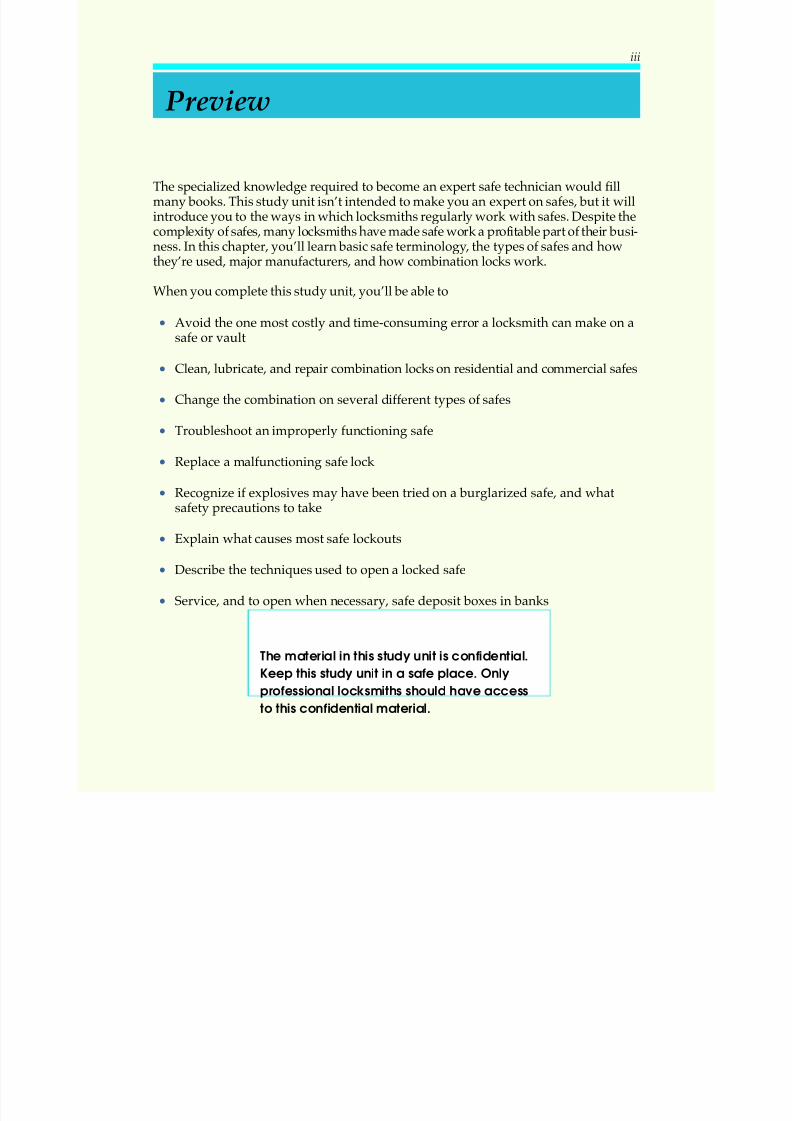
The specialized knowledge required to become an expert safe technician would fillmany books. This study unit isn’t intended to make you an expert on safes, but it willintroduce you to the ways in which locksmiths regularly work with safes. Despite thecomplexity of safes, many locksmiths have made safe work a profitable part of their busi-ness. In this chapter, you’ll learn basic safe terminology, the types of safes and howthey’re used, major manufacturers, and how combination locks work.
When you complete this study unit, you’ll be able to
• Avoid the one most costly and time-consuming error a locksmith can make on asafe or vault
• Clean, lubricate, and repair combination locks on residential and commercial safes
• Change the combination on several different types of safes
• Troubleshoot an improperly functioning safe
• Replace a malfunctioning safe lock
• Recognize if explosives may have been tried on a burglarized safe, and whatsafety precautions to take
• Explain what causes most safe lockouts
• Describe the techniques used to open a locked safe
• Service, and to open when necessary, safe deposit boxes in banks
Preview
iii
The material in this study unit is confidential.
Keep this study unit in a safe place. Only
professional locksmithsshould have acc ess
to this confidential material.
5/12/2018 10 Safes and Vaults - slidepdf.com
http://slidepdf.com/reader/full/10-safes-and-vaults-55a35b88b6c27 3/103
INTRODUCTION . . . . . . . . . . . . . . . . . . . . . . . . . . 1
Safe Tec hniciansand Loc ksmithsYour “ Golden Rule” for Safe Work
WORKING WITH SAFES . . . . . . . . . . . . . . . . . . . . . . 2
Where Are Safes Used?Modern Safes and VaultsSafe Services
SAFECONSTRUCTION . . . . . . . . . . . . . . . . . . . . . . 5
The Lock, the Doo r, and the BodyThe Comb ination Loc kThe Door and Bod yDetermining the “ Hand” o f the Loc k
THECOMBINATION LOCK . . . . . . . . . . . . . . . . . . . . 20
Comb ination Loc k Construc tionComb ination Loc k Theory
The Drop -in PointCom bination Numb ersYou Shouldn’ t UseDrive Cam Ga ting and Loc ationGear-Driven LocksRelockers
CHANGING A SAFECOMBINATION . . . . . . . . . . . . . . . 38
The Most Often Requested ServiceHole-Type LocksSc rew-Type Locks
Mesh-Type LocksKey-Changing Locks
SERVICING SAFES . . . . . . . . . . . . . . . . . . . . . . . . 55
Servic ing the Com bina tion Loc kServicing the Doo r: Hinges, Hand le, Bolt MechanismRep lac ing a Loc kServicing a Burglarized Safe
Contents
v
5/12/2018 10 Safes and Vaults - slidepdf.com
http://slidepdf.com/reader/full/10-safes-and-vaults-55a35b88b6c27 4/103
SAFELOCKOUTS . . . . . . . . . . . . . . . . . . . . . . . . . 65
What a Locksmith Should KnowTheory of Safe Manipula tion
All LockoutsAre Not AlikeTroub leshootingDrilling
SAFEDEPOSITBOXES. . . . . . . . . . . . . . . . . . . . . . . 71
What Isa Safe Deposit Box?Who Ca n Open a Safe Dep osit Box?Where Does the Locksmith Fit In?The Dual-Custody Lever Loc kOp ening a Loc ked Safe Dep osit Box
Ma king a “ First Key” for a Safe Deposit Box
THEKEY TO SUCCESS. . . . . . . . . . . . . . . . . . . . . . . 88
KEY POINTSTO REMEMBER. . . . . . . . . . . . . . . . . . . . 88
LOCKING ITUP! ANSWERS . . . . . . . . . . . . . . . . . . . . 91
EXAMINATION . . . . . . . . . . . . . . . . . . . . . . . . . . 93
COMING ATTRACTIONS . . . . . . . . . . . . . . . . . . . . . 99
vi Contents
5/12/2018 10 Safes and Vaults - slidepdf.com
http://slidepdf.com/reader/full/10-safes-and-vaults-55a35b88b6c27 5/103
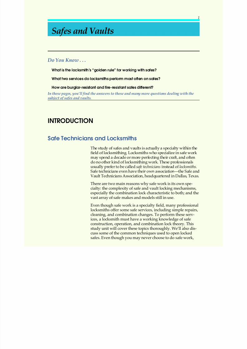
Do You Know . . .
What is the locksmith’s“golden rule” for working with safes?
What two servicesdo locksmithsperform most often on safes?
How are burglar-resistant and fire-resistant safes different?
In these pages, you’ll find the answers to these and many more questions dealing with the
subject of safes and vaults.
INTRODUCTION
Safe Techniciansand Locksmiths
The study of safes and vaults is actually a specialty within thefield of locksmithing. Locksmiths who specialize in safe work may spend a decade or more perfecting their craft, and oftendo no other kind of locksmithing work. These professionalsusually prefer to be called safe technicians instead of locksmiths.Safe technicians even have their own association—the Safe andVault Technicians Association, headquartered in Dallas, Texas.
There are two main reasons why safe work is its own spe-cialty: the complexity of safe and vault locking mechanisms,especially the combination lock characteristic to both; and the
vast array of safe makes and models still in use.
Even though safe work is a specialty field, many professionallocksmiths offer some safe services, including simple repairs,cleaning, and combination changes. To perform these serv-ices, a locksmith must have a working knowledge of safeconstruction, operation, and combination lock theory. Thisstudy unit will cover these topics thoroughly. We’ll also dis-cuss some of the common techniques used to open lockedsafes. Even though you may never choose to do safe work,
Safes and Vaults
1
5/12/2018 10 Safes and Vaults - slidepdf.com
http://slidepdf.com/reader/full/10-safes-and-vaults-55a35b88b6c27 6/103
you should at least be familiar with these techniques and theterminology associated with safe work.
Banks and other related institutions sometimes contract with in-
dependent locksmiths to service, repair, and rekey safe depositboxes, and to open locked safe deposit boxes when necessary.Safe deposit box work also will be covered in this study unit.
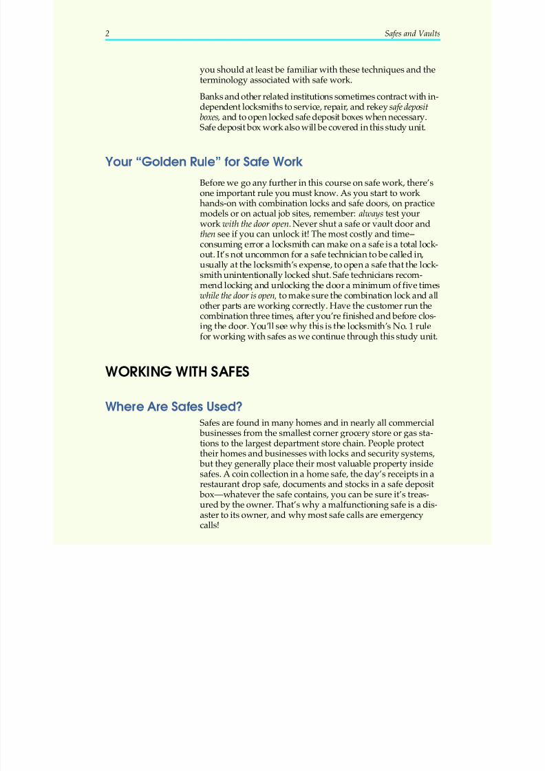
Your “Golden Rule” for Safe Work
Before we go any further in this course on safe work, there’sone important rule you must know. As you start to work hands-on with combination locks and safe doors, on practice
models or on actual job sites, remember: always test yourwork with the door open. Never shut a safe or vault door andthen see if you can unlock it! The most costly and time--consuming error a locksmith can make on a safe is a total lock-out. It’s not uncommon for a safe technician to be called in,usually at the locksmith’s expense, to open a safe that the lock-smith unintentionally locked shut. Safe technicians recom-mend locking and unlocking the door a minimum of five timeswhile the door is open, to make sure the combination lock and allother parts are working correctly. Have the customer run thecombination three times, after you’re finished and before clos-
ing the door. You’ll see why this is the locksmith’s No. 1 rulefor working with safes as we continue through this study unit.
WORKING WITH SAFES
Where Are Safes Used?Safes are found in many homes and in nearly all commercial
businesses from the smallest corner grocery store or gas sta-tions to the largest department store chain. People protecttheir homes and businesses with locks and security systems,
but they generally place their most valuable property insidesafes. A coin collection in a home safe, the day’s receipts in arestaurant drop safe, documents and stocks in a safe deposit
box—whatever the safe contains, you can be sure it’s treas-ured by the owner. That’s why a malfunctioning safe is a dis-aster to its owner, and why most safe calls are emergencycalls!
2 Safes and Vaults
5/12/2018 10 Safes and Vaults - slidepdf.com
http://slidepdf.com/reader/full/10-safes-and-vaults-55a35b88b6c27 7/103
Modern Safes and Vaults
Many years ago, before the invention of the combination lock, a
safe or vault was simply an extra-strong metal box fitted with aspecial type of key-operated lock. Today, however, the safes andvaults you’ll see in common use in homes and businesses are in-credibly secure. Typically made of iron, steel, or both, the mod-ern safe is a mini-fortress built to resist all sorts of forced entry.In addition, many safes are designed to survive fires, waterdamage, structural abuse, and even explosions.
Modern safes are fitted with complex combination locks,which help make them even more secure. Combination locksare keyless locks that, for all practical purposes, are pick-
proof. It’s nearly impossible for someone to open a combina-tion lock without knowing the combination. A combination isa set of letters or numbers unique to each lock. When dialedin sequence, this set of letters or numbers allows the bolt of the safe or vault door to be withdrawn and the door to open.(The basic parts and operation of the combination lock will beexplored a little later in this study unit.)
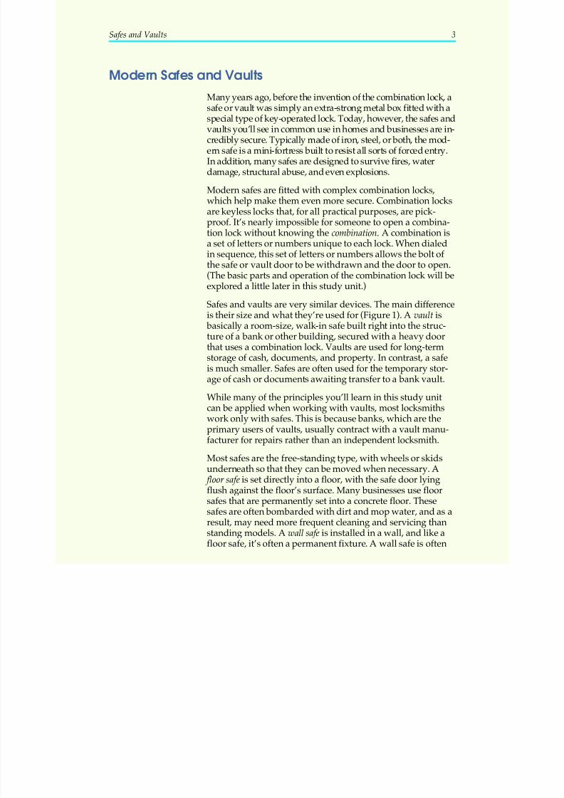
Safes and vaults are very similar devices. The main differenceis their size and what they’re used for (Figure 1). A vault is
basically a room-size, walk-in safe built right into the struc-
ture of a bank or other building, secured with a heavy doorthat uses a combination lock. Vaults are used for long-termstorage of cash, documents, and property. In contrast, a safeis much smaller. Safes are often used for the temporary stor-age of cash or documents awaiting transfer to a bank vault.
While many of the principles you’ll learn in this study unitcan be applied when working with vaults, most locksmithswork only with safes. This is because banks, which are theprimary users of vaults, usually contract with a vault manu-facturer for repairs rather than an independent locksmith.
Most safes are the free-standing type, with wheels or skidsunderneath so that they can be moved when necessary. A
floor safe is set directly into a floor, with the safe door lyingflush against the floor’s surface. Many businesses use floorsafes that are permanently set into a concrete floor. Thesesafes are often bombarded with dirt and mop water, and as aresult, may need more frequent cleaning and servicing thanstanding models. A wall safe is installed in a wall, and like afloor safe, it’s often a permanent fixture. A wall safe is often
Safes and Vaults 3
5/12/2018 10 Safes and Vaults - slidepdf.com
http://slidepdf.com/reader/full/10-safes-and-vaults-55a35b88b6c27 8/103
set in concrete to anchor it into the wall. A common type of wall safe is the round-door money chest.
Manufacturers were, and still are, constantly redesigningsafes in order to keep the inner workings secret, and to mini-
mize problems such as unintentional lockouts. Thus, just likeautomobile manufacturers, safe manufacturers over the yearshave produced many different makes and models of safes.And, because safes are built to last a long time, a vast array of safe makes and models is in use today. It’s not unusual, for ex-ample, to be called to examine a safe that’s more than 50 yearsold. Such a safe may have been made by any one of a hundreddifferent manufacturers. Not all safes are easily identified,however, and one of the safe technician’s challenges is to fig-ure out the make, model, and year of the safe, and the makeand model of the combination lock that operates it.
Safe Services
Safe work is a small part of most locksmiths’ trade, but it can be very profitable. Safe work often accounts for about 10 to 20percent of a locksmith’s business. Locksmiths perform thefollowing two services most often:
4 Safes and Vaults
(A) (B)
FIGURE 1—Vaults and safes are both used to store cash, doc uments, and property.However, a vault (a) is a room-size, walk-in storage structure. In contrast, a safe (b) is sma ller, usually free-standing or built into a wall.
5/12/2018 10 Safes and Vaults - slidepdf.com
http://slidepdf.com/reader/full/10-safes-and-vaults-55a35b88b6c27 9/103
1. Changing the combination on the combination lock
2. Troubleshooting, cleaning, and repairing the combina-tion lock and safe door
Locksmiths say that about 90 percent of the calls they receiveconcerning safes are requests to change the combination onthe combination lock. Businesses often request a combinationchange after an employee leaves or is fired, to keep the safe’scombination from becoming known to outsiders. Some resi-dential and commercial safe owners will call just to have asafe cleaned and serviced, but often these requests aren’tmade until the safe is working poorly, or not at all.
Calls on lockouts are rare. When locksmiths do receive a call
concerning a lockout, they ask one question first: Is the com- bination known? If the combination is known but the cus-tomer still can’t get the safe door open, the locksmith may tryto open the safe using troubleshooting techniques (we’ll re-view these techniques later). If the combination is unknown,the situation is much more complicated. Many locksmithswill immediately refer these cases to a safe and vault techni-cian, rather than attempt it themselves.
Note: In keeping with the locksmith’s code of ethics, youshould be careful to keep the information in this study unitout of the hands of those who aren’t in the locksmithingtrade. The locksmith’s code of ethics requires that a locksmithnot reveal the inner workings of locks to people outside thetrade. Safeguard your work and your reputation!
SAFECONSTRUCTION
The Lock, the Door, and the Body
Before you can successfully clean, repair, or open a safe, youneed to understand the basic operating principles of safes.First, we’ll look at the workings of the most vital part: thecombination lock. Then, we’ll look at the construction of asafe body to understand how the combination lock workswith all other parts of the safe.
Safes and Vaults 5
5/12/2018 10 Safes and Vaults - slidepdf.com
http://slidepdf.com/reader/full/10-safes-and-vaults-55a35b88b6c27 10/103
Although all safes work on certain basic principles, differentmakes and models of safes will differ in many details. Toservice them properly, you’ll need to know how to identifythem and how they differ from one another. We’ll finish up
this section by comparing several of the most popular brand-name safe manufacturers and their products.
The Combination Lock
Over the years, locksmiths and safe technicians adopted vari-ous names for the different parts of combination locks. Thiscaused confusion when they tried to order parts from a
manufacturer, because the factory couldn’t always tell whichpart or parts they wanted. Standardization of the names of parts was sorely needed. Finally, Sargent & Greenleaf Inc.,one of the foremost makers of combination locks, published acombination lock glossary that pictured and named combina-tion lock parts. The names used in this reference work arenow considered industry standards, and are used in this text.
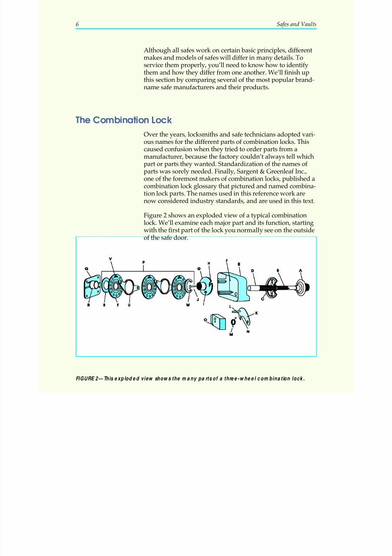
Figure 2 shows an exploded view of a typical combinationlock. We’ll examine each major part and its function, startingwith the first part of the lock you normally see on the outsideof the safe door.
6 Safes and Vaults
FIGURE 2—This exploded view shows the many pa rts of a three-wheel combination lock.
5/12/2018 10 Safes and Vaults - slidepdf.com
http://slidepdf.com/reader/full/10-safes-and-vaults-55a35b88b6c27 11/103
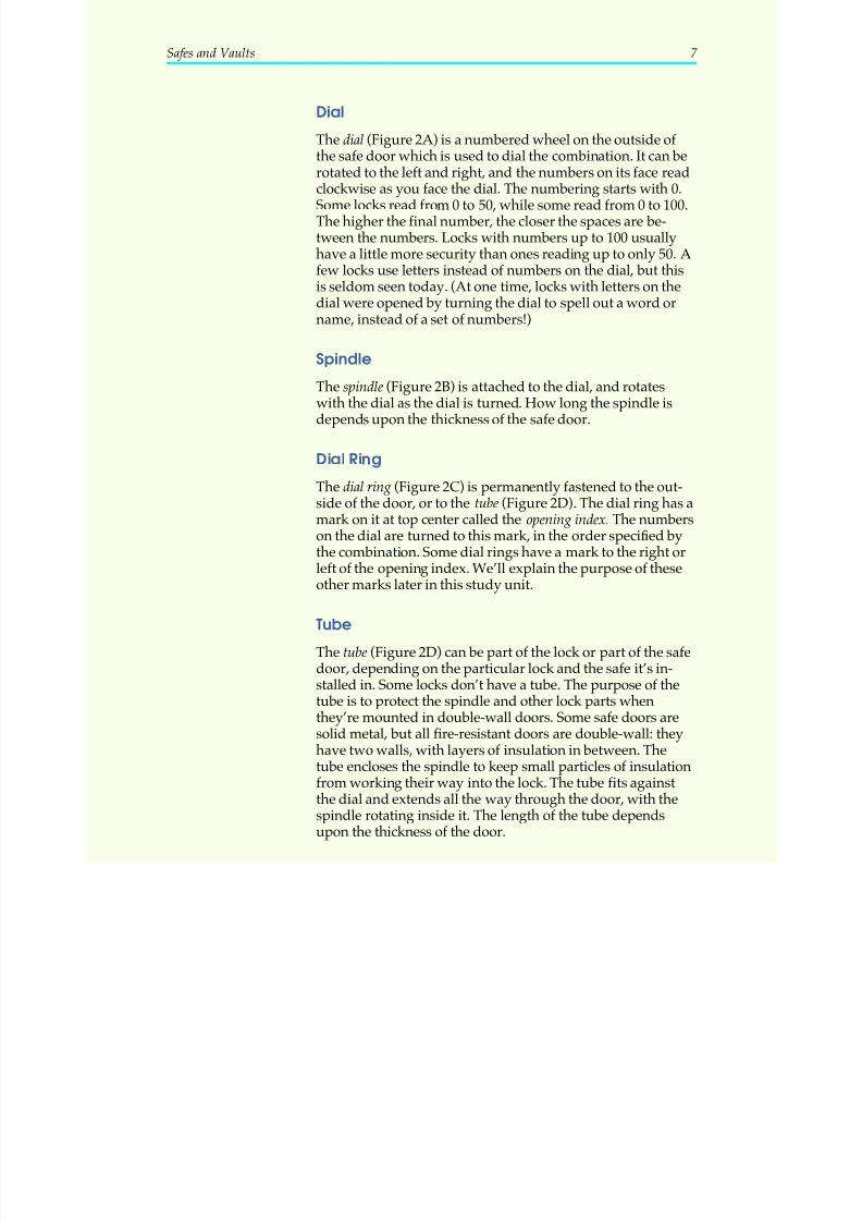
Dial
The dial (Figure 2A) is a numbered wheel on the outside of the safe door which is used to dial the combination. It can be
rotated to the left and right, and the numbers on its face readclockwise as you face the dial. The numbering starts with 0.Some locks read from 0 to 50, while some read from 0 to 100.The higher the final number, the closer the spaces are be-tween the numbers. Locks with numbers up to 100 usuallyhave a little more security than ones reading up to only 50. Afew locks use letters instead of numbers on the dial, but thisis seldom seen today. (At one time, locks with letters on thedial were opened by turning the dial to spell out a word orname, instead of a set of numbers!)
Spindle
The spindle (Figure 2B) is attached to the dial, and rotateswith the dial as the dial is turned. How long the spindle isdepends upon the thickness of the safe door.
Dial Ring
The dial ring (Figure 2C) is permanently fastened to the out-side of the door, or to the tube (Figure 2D). The dial ring has a
mark on it at top center called the opening index. The numberson the dial are turned to this mark, in the order specified bythe combination. Some dial rings have a mark to the right orleft of the opening index. We’ll explain the purpose of theseother marks later in this study unit.
Tube
The tube (Figure 2D) can be part of the lock or part of the safedoor, depending on the particular lock and the safe it’s in-
stalled in. Some locks don’t have a tube. The purpose of thetube is to protect the spindle and other lock parts whenthey’re mounted in double-wall doors. Some safe doors aresolid metal, but all fire-resistant doors are double-wall: theyhave two walls, with layers of insulation in between. Thetube encloses the spindle to keep small particles of insulationfrom working their way into the lock. The tube fits againstthe dial and extends all the way through the door, with thespindle rotating inside it. The length of the tube dependsupon the thickness of the door.
Safes and Vaults 7
5/12/2018 10 Safes and Vaults - slidepdf.com
http://slidepdf.com/reader/full/10-safes-and-vaults-55a35b88b6c27 12/103
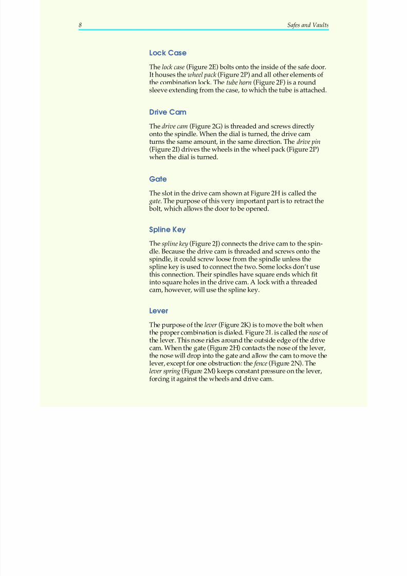
Lock Case
The lock case (Figure 2E) bolts onto the inside of the safe door.It houses the wheel pack (Figure 2P) and all other elements of
the combination lock. The tube horn (Figure 2F) is a roundsleeve extending from the case, to which the tube is attached.
Drive Cam
The drive cam (Figure 2G) is threaded and screws directlyonto the spindle. When the dial is turned, the drive camturns the same amount, in the same direction. The drive pin(Figure 2I) drives the wheels in the wheel pack (Figure 2P)when the dial is turned.
Gate
The slot in the drive cam shown at Figure 2H is called the gate. The purpose of this very important part is to retract the bolt, which allows the door to be opened.
Spline Key
The spline key (Figure 2J) connects the drive cam to the spin-dle. Because the drive cam is threaded and screws onto thespindle, it could screw loose from the spindle unless thespline key is used to connect the two. Some locks don’t usethis connection. Their spindles have square ends which fitinto square holes in the drive cam. A lock with a threadedcam, however, will use the spline key.
Lever
The purpose of the lever (Figure 2K) is to move the bolt whenthe proper combination is dialed. Figure 2L is called the nose of the lever. This nose rides around the outside edge of the drivecam. When the gate (Figure 2H) contacts the nose of the lever,the nose will drop into the gate and allow the cam to move thelever, except for one obstruction: the fence (Figure 2N). Thelever spring (Figure 2M) keeps constant pressure on the lever,forcing it against the wheels and drive cam.
8 Safes and Vaults
5/12/2018 10 Safes and Vaults - slidepdf.com
http://slidepdf.com/reader/full/10-safes-and-vaults-55a35b88b6c27 13/103
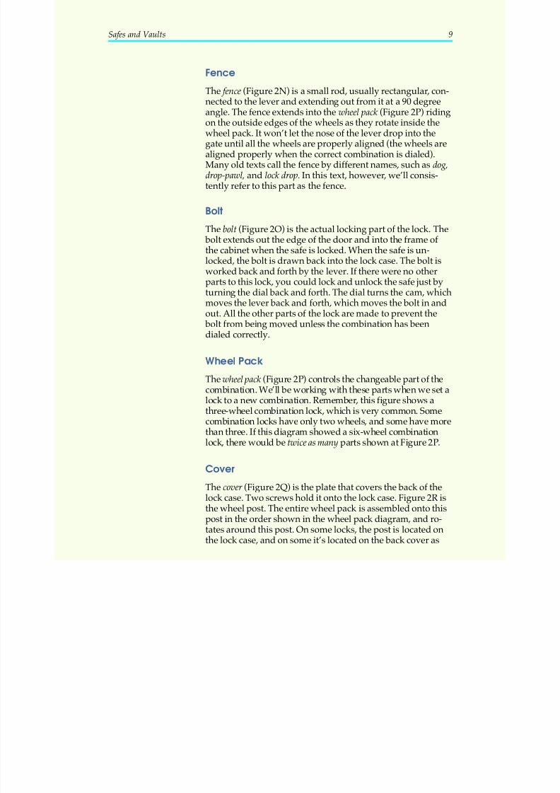
Fence
The fence (Figure 2N) is a small rod, usually rectangular, con-nected to the lever and extending out from it at a 90 degree
angle. The fence extends into the wheel pack (Figure 2P) ridingon the outside edges of the wheels as they rotate inside thewheel pack. It won’t let the nose of the lever drop into thegate until all the wheels are properly aligned (the wheels arealigned properly when the correct combination is dialed).Many old texts call the fence by different names, such as dog,drop-pawl, and lock drop. In this text, however, we’ll consis-tently refer to this part as the fence.
Bolt
The bolt (Figure 2O) is the actual locking part of the lock. The bolt extends out the edge of the door and into the frame of the cabinet when the safe is locked. When the safe is un-locked, the bolt is drawn back into the lock case. The bolt isworked back and forth by the lever. If there were no otherparts to this lock, you could lock and unlock the safe just byturning the dial back and forth. The dial turns the cam, whichmoves the lever back and forth, which moves the bolt in andout. All the other parts of the lock are made to prevent the
bolt from being moved unless the combination has been
dialed correctly.
Wheel Pack
The wheel pack (Figure 2P) controls the changeable part of thecombination. We’ll be working with these parts when we set alock to a new combination. Remember, this figure shows athree-wheel combination lock, which is very common. Somecombination locks have only two wheels, and some have morethan three. If this diagram showed a six-wheel combinationlock, there would be twice as many parts shown at Figure 2P.
Cover
The cover (Figure 2Q) is the plate that covers the back of thelock case. Two screws hold it onto the lock case. Figure 2R isthe wheel post. The entire wheel pack is assembled onto thispost in the order shown in the wheel pack diagram, and ro-tates around this post. On some locks, the post is located onthe lock case, and on some it’s located on the back cover as
Safes and Vaults 9
5/12/2018 10 Safes and Vaults - slidepdf.com
http://slidepdf.com/reader/full/10-safes-and-vaults-55a35b88b6c27 14/103
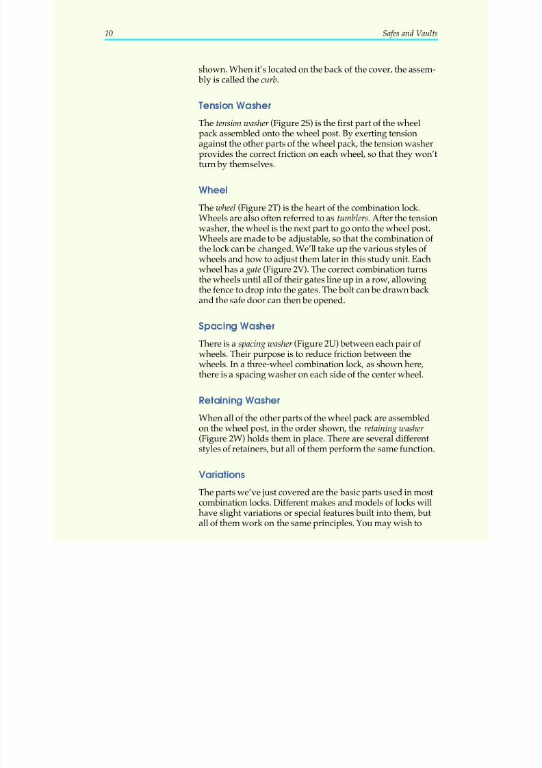
shown. When it’s located on the back of the cover, the assem- bly is called the curb.
Tension WasherThe tension washer (Figure 2S) is the first part of the wheelpack assembled onto the wheel post. By exerting tensionagainst the other parts of the wheel pack, the tension washerprovides the correct friction on each wheel, so that they won’tturn by themselves.
Wheel
The wheel (Figure 2T) is the heart of the combination lock.
Wheels are also often referred to as tumblers. After the tensionwasher, the wheel is the next part to go onto the wheel post.Wheels are made to be adjustable, so that the combination of the lock can be changed. We’ll take up the various styles of wheels and how to adjust them later in this study unit. Eachwheel has a gate (Figure 2V). The correct combination turnsthe wheels until all of their gates line up in a row, allowingthe fence to drop into the gates. The bolt can be drawn back and the safe door can then be opened.
Spacing Washer
There is a spacing washer (Figure 2U) between each pair of wheels. Their purpose is to reduce friction between thewheels. In a three-wheel combination lock, as shown here,there is a spacing washer on each side of the center wheel.
Retaining Washer
When all of the other parts of the wheel pack are assembledon the wheel post, in the order shown, the retaining washer (Figure 2W) holds them in place. There are several differentstyles of retainers, but all of them perform the same function.
Variations
The parts we’ve just covered are the basic parts used in mostcombination locks. Different makes and models of locks willhave slight variations or special features built into them, butall of them work on the same principles. You may wish to
10 Safes and Vaults
5/12/2018 10 Safes and Vaults - slidepdf.com
http://slidepdf.com/reader/full/10-safes-and-vaults-55a35b88b6c27 15/103
keep Figure 2 handy as we go through the rest of this studyunit, because we’ll be referring to these parts frequently.
Now that we’ve identified the basic parts of the combination
lock, we’ll look at the the following:
• What the door and body of the safe are made of
• What the UL rating of a safe is and what it reveals
• How to find the make and model number of a safe
• How to determine the “hand” of the lock
This section will also introduce two special security featuresthat we’ll explore more fully later: the relocking mechanism or
relocker and the hardplate.
The Door and Body
The door and body jambs of very old safes usually are madeof cast iron, with solid iron or steel forming the safe’s top,
bottom and sides.
In the 1920s, Underwriters’ Laboratories (UL) began testing
safes and rating them for insurance purposes. In response,manufacturers began to extensively redesign their safes. The“iron age” of safe-manufacturing waned, and the modernpressed-steel type of manufacture began. Most safes today aremade of steel. (Manganese steel was used in bank-quality safescalled cannon balls.) The steel is also often case-hardened, mean-ing that the exterior surfaces of the steel have a hardenedouter skin that resists drilling.
Burglar Resistance and Fire Resistance
The materials and construction of a safe’s door and body willdepend on whether the safe is meant to be fire-resistant orburglar-resistant. If the safe has a UL label, the label will tellyou which kind of safe it is.
Why these two categories? Because people buy safes to pro-tect their property against two different kinds of danger:thieves and fire. A convenience store manager, for example,is more likely to lose cash receipts in a holdup or throughemployee pilfering than by fire. This manager will want a
Safes and Vaults 11
5/12/2018 10 Safes and Vaults - slidepdf.com
http://slidepdf.com/reader/full/10-safes-and-vaults-55a35b88b6c27 16/103
safe that’s mainly burglar-resistant. On the other hand, a data-processing manager may need a secure place to store computerdisks and tapes, or paper records such as spreadsheets, ledgers,etc. These items wouldn’t be of much value to a thief, but they
could be destroyed in a fire. The data-processing managerwill want a safe that’s fire-resistant.
Burglar-resistant safes are often made of solid steel, or of aconcrete-like compound sandwiched between thick sheetsof steel. They have special security features, such as recesseddoors and heavy-duty hinges that resist prying and hammering.As you may guess, a lockout on a burglar-resistant safe causesmuch grief because, when locked, these safes are made toremain locked. They aren’t very good at protecting theircontents from fire, however. This is because steel is an excellentheat conductor. If the outside of the safe heats up in a fire, theheat can quickly radiate to the interior, damaging or destroyingany paper records or cash in it.
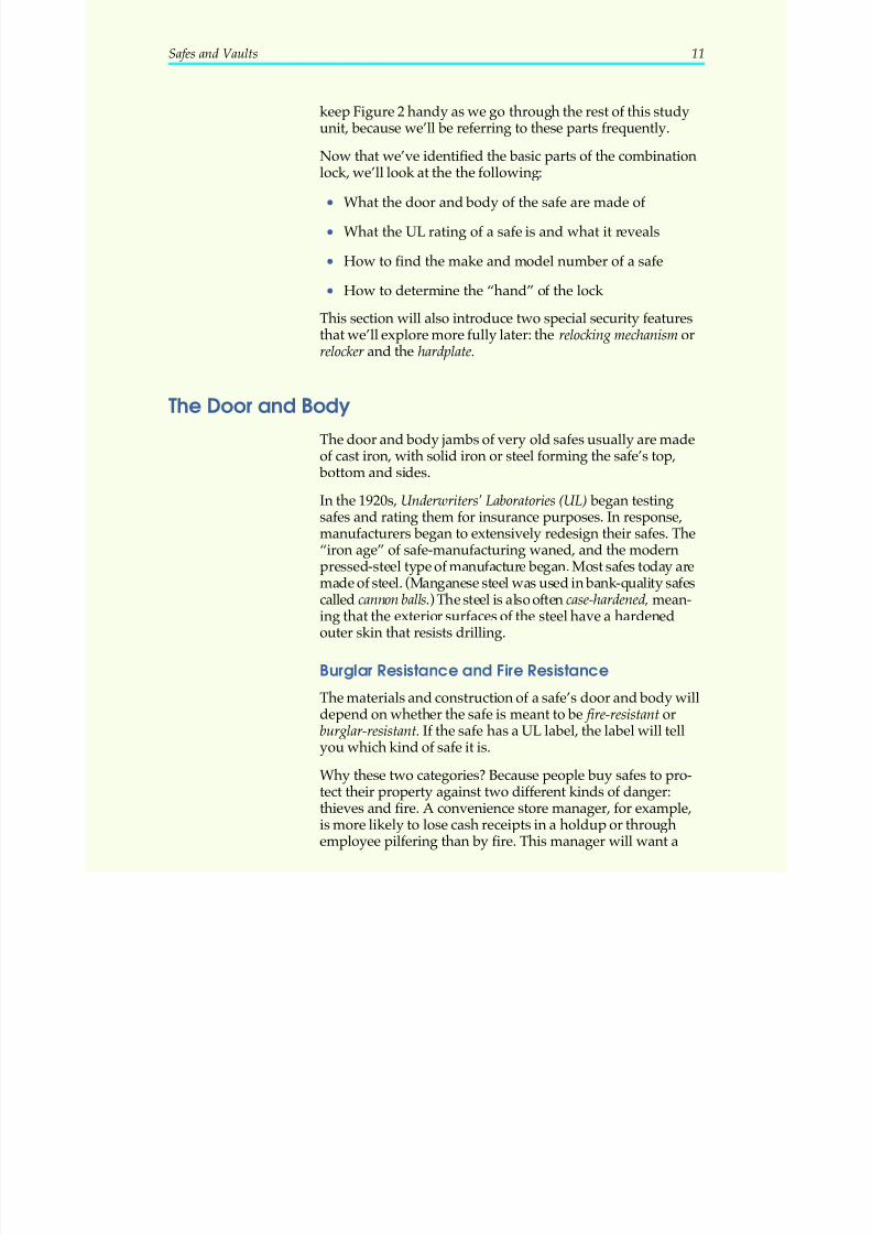
The compact security safe shown in Figure 3 is mainly burglar-resistant. It’s constructed of solid steel, but doesn’thave insulation, and therefore wouldn’t protect its contentsfor long in an intense fire. However, it would provide excel-lent protection of its contents from burglary, and thereforewould have a UL rating of B (burglary). We’ll explain thisrating and other UL ratings in a moment.
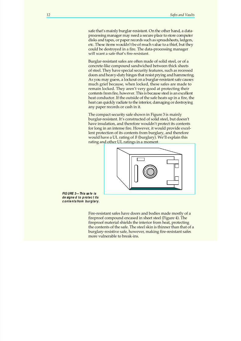
Fire-resistant safes have doors and bodies made mostly of afireproof compound encased in sheet steel (Figure 4). Thefireproof material shields the interior from heat, protectingthe contents of the safe. The steel skin is thinner than that of a
burglary-resistive safe, however, making fire-resistant safesmore vulnerable to break-ins.
12 Safes and Vaults
FIGURE 3—This safe is designed to protect its contents from burglary.
5/12/2018 10 Safes and Vaults - slidepdf.com
http://slidepdf.com/reader/full/10-safes-and-vaults-55a35b88b6c27 17/103
In an advertisement for such a safe, the safe’s fire-resistancerating would be mentioned first, and the insulation wouldalso be mentioned in the description. There would be no bur-glary rating; most fire-resistant safes don’t meet the require-
ments of burglary ratings. However, a manufacturer wouldpoint out that these safes do have relockers, hardplates, anddeadbolts to beef up their security against break-ins.
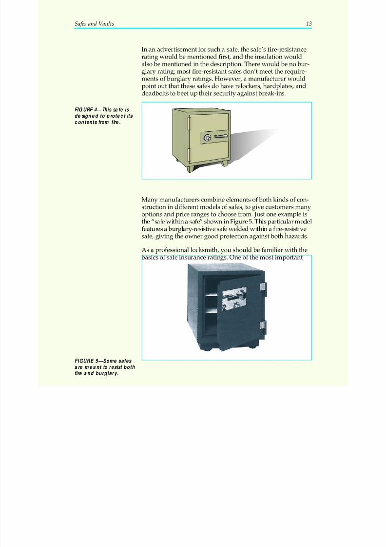
Many manufacturers combine elements of both kinds of con-struction in different models of safes, to give customers manyoptions and price ranges to choose from. Just one example isthe “safe within a safe” shown in Figure 5. This particular model
features a burglary-resistive safe welded within a fire-resistivesafe, giving the owner good protection against both hazards.
As a professional locksmith, you should be familiar with the basics of safe insurance ratings. One of the most important
Safes and Vaults 13
FIGURE 4—This safe is designed to protect its contents from fire.
FIGURE 5—Some safes are meant to resist both fire and burglary.
5/12/2018 10 Safes and Vaults - slidepdf.com
http://slidepdf.com/reader/full/10-safes-and-vaults-55a35b88b6c27 18/103
ratings is the mercantile safe classification. This rating indicatesa safe that is suitable for commercial applications (stores and
businesses). The mercantile rating is often indicated by theletters B or C. A safe rated C has a 1-inch thick steel door and
(at least) a 1/2-inch thick steel body. A safe rated B has a steeldoor less than 1 inch thick, and a steel body less than 1/2 inchthick. In this class, B and C are the most common ratings.
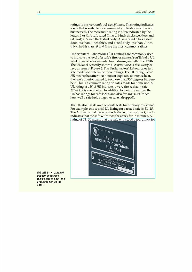
Underwriters’ Laboratories (UL)® ratings are commonly usedto indicate the level of a safe’s fire resistance. You’ll find a ULlabel on most safes manufactured during and after the 1920s.The UL label typically shows a temperature and time classifica-tion, as seen in Figure 6. The Underwriters’ Laboratories testsafe models to determine these ratings. The UL rating 350–2
HR means that after two hours of exposure to intense heat,the safe’s interior heated to no more than 350 degrees Fahren-heit. This is a common rating on safes made for home use. AUL rating of 125–2 HR indicates a very fire-resistant safe;125–4 HR is even better. In addition to their fire ratings, theUL has ratings for safe locks, and also for drop tests (to seehow well a safe holds together when dropped).
The UL also has its own separate tests for burglary resistance.For example, one typical UL listing for a tested safe is TL–15.The TL means that the safe was tested with a tool attack ; the 15
indicates that the safe withstood the attack for 15 minutes. Arating of TL–30 means that the safe withstood a tool attack for
14 Safes and Vaults
FIGURE 6—A UL label usually shows the temperature and time classification of the safe.
5/12/2018 10 Safes and Vaults - slidepdf.com
http://slidepdf.com/reader/full/10-safes-and-vaults-55a35b88b6c27 19/103
30 minutes. A TRTL–30 listing means that a tested safe with-stood a blowtorch (TR) and tool attack for 30 minutes. Again,these are only a few of the UL ratings you might find on asafe. (You can obtain a complete UL listing for safes from a
variety of reference sources.)
Relockers and Hardplates
Safe doors may contain two other items the locksmith should be aware of: relockers and hardplates.
A relocker is a secondary locking device that’s set off by tam-pering. The relocking device may be within the lock itself,within the safe door, or both. As its name implies, it inde-pendently relocks the door, so that even if the combination
lock is defeated, the door won’t open. We’ll examine differentkinds of relockers in the next section of this study unit.
The hardplate is a piece of drill-resistant steel mounted withinthe safe door to protect the lock from drill attacks. Hardplatescome in different sizes, shapes, and thicknesses. Some hard-plates are made big enough to protect both the lock and thewhole bolt mechanism in the door from drilling. We’ll look athardplates more closely when we cover drilling in a later sec-tion in this study unit.
All of the above is important to the locksmith for two mainreasons. First, if you have to replace a lock on a safe door ordrill through the door, you should know what kind of mate-rial(s) you may be dealing with. Second, if you’re servicing orreplacing a lock on a safe door, you should know if there’s arelocker and how to disarm it.
The Make and Model Number
How can you recognize a particular make and model of safe?Most locksmiths have no trouble identifying new safes. The
manufacturer’s name and model number are usually markedprominently on the safe. By checking the number in a referencemanual or a manufacturer’s catalog, you can easily find outwhat you need to know: what the safe is made of, what make of lock it takes, how the door functions, and so on. Some of the
best-known safe manufacturers in use today are the following:
• Mosler
• Diebold
Safes and Vaults 15
5/12/2018 10 Safes and Vaults - slidepdf.com
http://slidepdf.com/reader/full/10-safes-and-vaults-55a35b88b6c27 20/103
• Herring-Hall-Marvin (H.H.M.)
• Meilink
• Reliable
• Cary (discontinued, but still many in use)
• Syracuse
• Baum
• Remington Rand
• Gardall
• Sentry
• American Security Products Company (AMSEC), makerof the popular Star and Major floor safes
Some major combination lock manufacturers are the following:
• Sargent & Greenleaf (S&G)
• Yale
• LaGuard
• ILCO
One of these lock brands could be seen on a variety of safemodels. For example, 90 percent of Meilink safes areequipped with Yale locks. Several of Gardall’s models comewith S&G locks. However, one of the largest manufacturers of safes, Mosler, makes some of its own locks.
Now, what if a safe was made 30 or more years ago? Theseare the safes that are harder to identify. A safe that old may
well have been repainted, repaired, or survived a fire, any of which could have obliterated its make and model number.Some safes have the manufacturer’s name stamped on theface of the door in raised letters, which can be felt or seen bylooking sideways across the door surface.
Sometimes a name can be found on the combination dial hub, but be warned: this is often the name of the lock manufac-turer, not the safe manufacturer. Although there have been ahundred or more safe manufacturers over the years, there are
16 Safes and Vaults
5/12/2018 10 Safes and Vaults - slidepdf.com
http://slidepdf.com/reader/full/10-safes-and-vaults-55a35b88b6c27 21/103
only a handful of major manufacturers of combination locks,and these locks will be found on many different makes andmodels of safes. It’s a common mistake of locksmiths to iden-tify a safe as a Sargent or a Yale, when actually there’s no
such make.
There’s another way to determine the make of a safe, andthat’s to become familiar with the peculiar identifying charac-teristics of different manufacturers. The different shapes andstyles of dials, handles, body and door corners, wheels andcasters all give a clue as to who the manufacturer is. As youcan guess, identifying a safe this way is an art, like identify-ing antique cars by the shape of their tailfins and headlights.
For all practical purposes, locksmiths rarely have to identify a
safe this old or obscure, as long as it’s open. If the safe is open,
Safes and Vaults 17
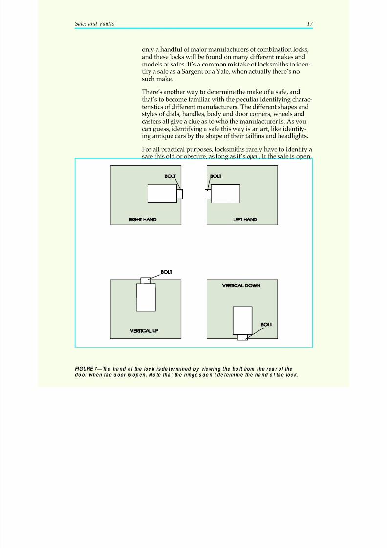
FIGURE 7—The hand of the lock is determined by viewing the bolt from the rea r of the door when the door is open. Note that the hinges don’t determine the hand of the lock.

5/12/2018 10 Safes and Vaults - slidepdf.com
http://slidepdf.com/reader/full/10-safes-and-vaults-55a35b88b6c27 22/103
a well-trained locksmith will be able to service or replace thecombination lock, and with good mechanical aptitude, will
be able to service the working parts of the door to give themmany more years of service.
Determining the “Hand” of the Lock
Sometimes you need to order a replacement lock for a safe, oneof the first things you’ll need to know is the hand of the lock.
Safe locks are mounted in four different positions: right-hand,left-hand, vertical up, and vertical down (Figure 7). Remember,these are the positions as you’re facing the rear of an open door.
18 Safes and Vaults
5/12/2018 10 Safes and Vaults - slidepdf.com
http://slidepdf.com/reader/full/10-safes-and-vaults-55a35b88b6c27 23/103
Safes and Vaults 19
Locking It Up! 1
At the end of each section in your Professional Locksmith texts, you’llbe asked to pause and check your understanding of what you’ve justread by completing a Locking It Up! quiz. Writing the answers to thesequestions will help you review what you’ve studied so far. Please com-plete Locking It Up! 1 now.
1. What is the difference between a locksmith and a safe and vault
technician?
_____________________________________________________________________
_____________________________________________________________________
2. What is the most expensive mistake a locksmith can make whileworking on a safe?
_____________________________________________________________________
_____________________________________________________________________
3. What are the two most common tasks locksmiths perform on safes?
_____________________________________________________________________
_____________________________________________________________________
4. If a customer calls and says a safe is locked up and won’t open, thelocksmith will usually ask if the ________________ is known. This in-dicates how much time and effort it will probably take to get the safeopen.
5. True or False? It’s rare to find a safe that’s more than 50 years old, be-cause they wear out and are replaced often.
Check your answers with those on page 91.
5/12/2018 10 Safes and Vaults - slidepdf.com
http://slidepdf.com/reader/full/10-safes-and-vaults-55a35b88b6c27 24/103
THECOMBINATION LOCK
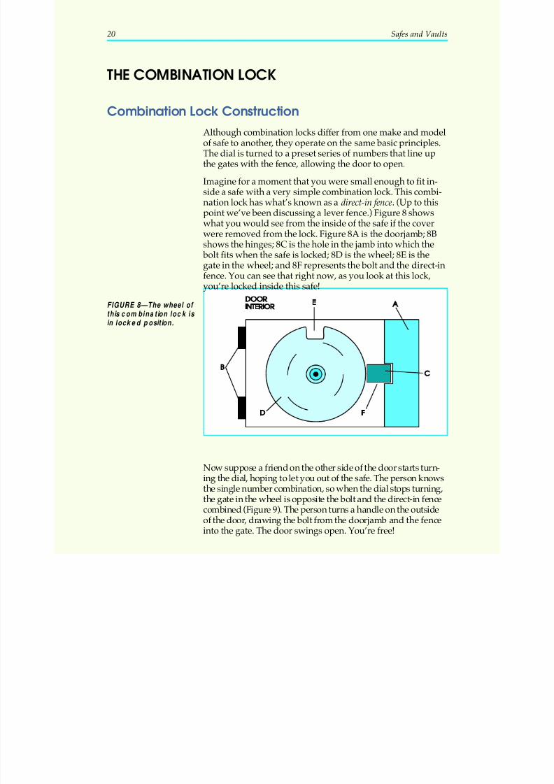
Combination Lock ConstructionAlthough combination locks differ from one make and modelof safe to another, they operate on the same basic principles.The dial is turned to a preset series of numbers that line upthe gates with the fence, allowing the door to open.
Imagine for a moment that you were small enough to fit in-side a safe with a very simple combination lock. This combi-nation lock has what’s known as a direct-in fence. (Up to thispoint we’ve been discussing a lever fence.) Figure 8 shows
what you would see from the inside of the safe if the coverwere removed from the lock. Figure 8A is the doorjamb; 8Bshows the hinges; 8C is the hole in the jamb into which the
bolt fits when the safe is locked; 8D is the wheel; 8E is thegate in the wheel; and 8F represents the bolt and the direct-infence. You can see that right now, as you look at this lock,you’re locked inside this safe!
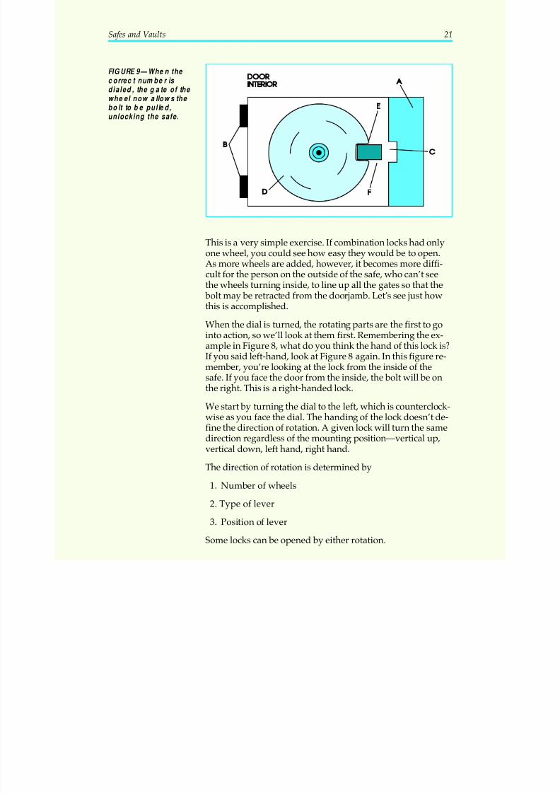
Now suppose a friend on the other side of the door starts turn-ing the dial, hoping to let you out of the safe. The person knowsthe single number combination, so when the dial stops turning,the gate in the wheel is opposite the bolt and the direct-in fencecombined (Figure 9). The person turns a handle on the outsideof the door, drawing the bolt from the doorjamb and the fenceinto the gate. The door swings open. You’re free!
20 Safes and Vaults
FIGURE 8—The wheel of this combination lock is in locked position.
5/12/2018 10 Safes and Vaults - slidepdf.com
http://slidepdf.com/reader/full/10-safes-and-vaults-55a35b88b6c27 25/103
This is a very simple exercise. If combination locks had onlyone wheel, you could see how easy they would be to open.As more wheels are added, however, it becomes more diffi-cult for the person on the outside of the safe, who can’t seethe wheels turning inside, to line up all the gates so that the
bolt may be retracted from the doorjamb. Let’s see just howthis is accomplished.
When the dial is turned, the rotating parts are the first to go
into action, so we’ll look at them first. Remembering the ex-ample in Figure 8, what do you think the hand of this lock is?If you said left-hand, look at Figure 8 again. In this figure re-member, you’re looking at the lock from the inside of thesafe. If you face the door from the inside, the bolt will be onthe right. This is a right-handed lock.
We start by turning the dial to the left, which is counterclock-wise as you face the dial. The handing of the lock doesn’t de-fine the direction of rotation. A given lock will turn the samedirection regardless of the mounting position—vertical up,
vertical down, left hand, right hand.
The direction of rotation is determined by
1. Number of wheels
2. Type of lever
3. Position of lever
Some locks can be opened by either rotation.
Safes and Vaults 21
FIGURE 9—When the correc t numbe r is dialed, the gate of the wheel now allows the bolt to be pulled,unlocking the safe.
5/12/2018 10 Safes and Vaults - slidepdf.com
http://slidepdf.com/reader/full/10-safes-and-vaults-55a35b88b6c27 26/103
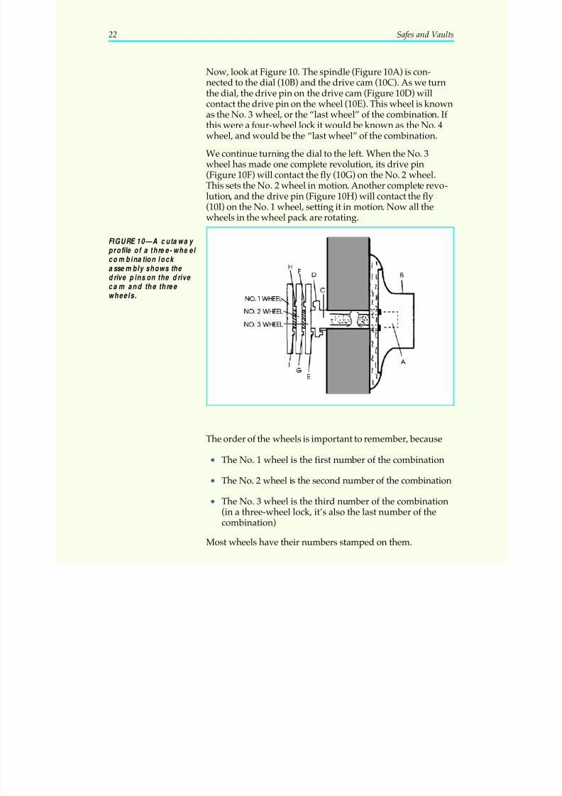
Now, look at Figure 10. The spindle (Figure 10A) is con-nected to the dial (10B) and the drive cam (10C). As we turnthe dial, the drive pin on the drive cam (Figure 10D) willcontact the drive pin on the wheel (10E). This wheel is known
as the No. 3 wheel, or the “last wheel” of the combination. If this were a four-wheel lock it would be known as the No. 4wheel, and would be the “last wheel” of the combination.
We continue turning the dial to the left. When the No. 3wheel has made one complete revolution, its drive pin(Figure 10F) will contact the fly (10G) on the No. 2 wheel.This sets the No. 2 wheel in motion. Another complete revo-lution, and the drive pin (Figure 10H) will contact the fly(10I) on the No. 1 wheel, setting it in motion. Now all thewheels in the wheel pack are rotating.
The order of the wheels is important to remember, because
• The No. 1 wheel is the first number of the combination
• The No. 2 wheel is the second number of the combination
• The No. 3 wheel is the third number of the combination(in a three-wheel lock, it’s also the last number of thecombination)
Most wheels have their numbers stamped on them.
22 Safes and Vaults
FIGURE 10—A cutaway profile of a three-wheel combination lock assembly shows the drive pins on the drive ca m and the three wheels.
5/12/2018 10 Safes and Vaults - slidepdf.com
http://slidepdf.com/reader/full/10-safes-and-vaults-55a35b88b6c27 27/103
Remember that the No. 1 wheel, the first number of the com- bination, is the one farthest away from the drive cam. Thewheel next to the drive cam is the last wheel, and the lastnumber of the combination. Don’t confuse them! Inexperienced
locksmiths have set a desired combination backwards be-cause they didn’t understand this sequence.
On a three-wheel lock, you must turn the dial four completerevolutions to make the No. 1 wheel turn one complete revolu-tion. Why four turns? Because the drive cam, with its own drivepin, actually acts as a fourth wheel in this three-wheel lock. Ittakes four complete turns to get the No. 1 wheel turning.
A note on turning the dial: never spin the dial hard, snappingthe drive pins together, because prolonged abuse can wear or
break them. Also, be careful to dial your numbers up to theopening index, not past it. Spinning the dial will also causethe wheels to turn too far. If you dial past the mark, you can’t
bring the wheel backwards by turning the dial backwards;you just have to start again.
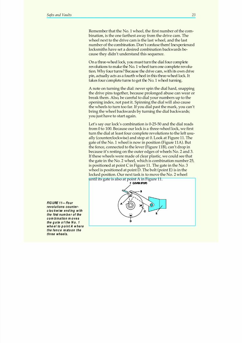
Let’s say our lock’s combination is 0-25-50 and the dial readsfrom 0 to 100. Because our lock is a three-wheel lock, we firstturn the dial at least four complete revolutions to the left usu-ally (counterclockwise) and stop at 0. Look at Figure 11. Thegate of the No. 1 wheel is now in position (Figure 11A). Butthe fence, connected to the lever (Figure 11B), can’t drop in
because it’s resting on the outer edges of wheels No. 2 and 3.If these wheels were made of clear plastic, we could see thatthe gate in the No. 2 wheel, which is combination number 25,is positioned at point C in Figure 11. The gate in the No. 3wheel is positioned at point D. The bolt (point E) is in thelocked position. Our next task is to move the No. 2 wheeluntil its gate is also at point A in Figure 11.
Safes and Vaults 23
FIGURE 11—Four revolutions counter- clockwise ending with the first number of the combination moves the gate of the No. 1wheel to point A where the fence rests on the three wheels.
5/12/2018 10 Safes and Vaults - slidepdf.com
http://slidepdf.com/reader/full/10-safes-and-vaults-55a35b88b6c27 28/103
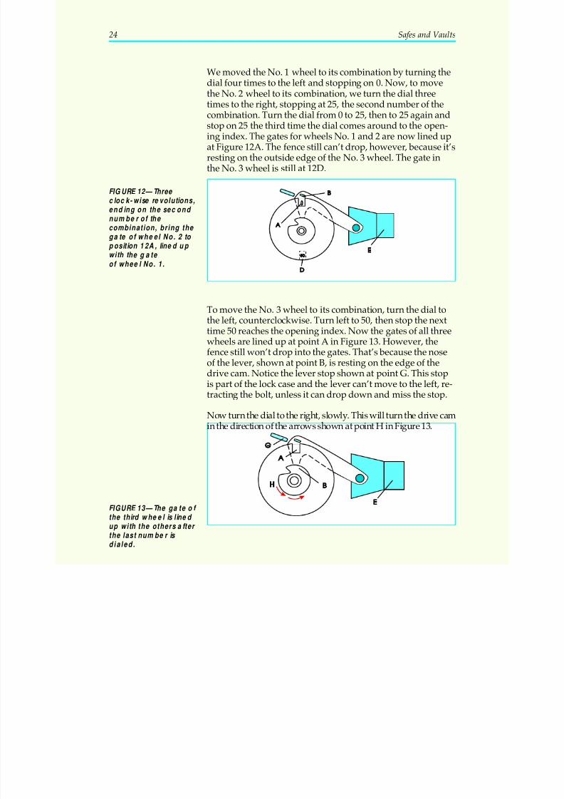
We moved the No. 1 wheel to its combination by turning thedial four times to the left and stopping on 0. Now, to movethe No. 2 wheel to its combination, we turn the dial threetimes to the right, stopping at 25, the second number of the
combination. Turn the dial from 0 to 25, then to 25 again andstop on 25 the third time the dial comes around to the open-ing index. The gates for wheels No. 1 and 2 are now lined upat Figure 12A. The fence still can’t drop, however, because it’sresting on the outside edge of the No. 3 wheel. The gate inthe No. 3 wheel is still at 12D.
To move the No. 3 wheel to its combination, turn the dial tothe left, counterclockwise. Turn left to 50, then stop the nexttime 50 reaches the opening index. Now the gates of all threewheels are lined up at point A in Figure 13. However, thefence still won’t drop into the gates. That’s because the noseof the lever, shown at point B, is resting on the edge of thedrive cam. Notice the lever stop shown at point G. This stopis part of the lock case and the lever can’t move to the left, re-tracting the bolt, unless it can drop down and miss the stop.
Now turn the dial to the right, slowly. This will turn the drive camin the direction of the arrows shown at point H in Figure 13.
24 Safes and Vaults
FIGURE 12—Three clock-wise revolutions,ending on the second number of the
combination, bring the gate of wheel No. 2 to position 12A, lined up with the gate of wheel No. 1.
FIGURE 13—The ga te of the third wheel is lined up with the others after the last number is dialed.
5/12/2018 10 Safes and Vaults - slidepdf.com
http://slidepdf.com/reader/full/10-safes-and-vaults-55a35b88b6c27 29/103
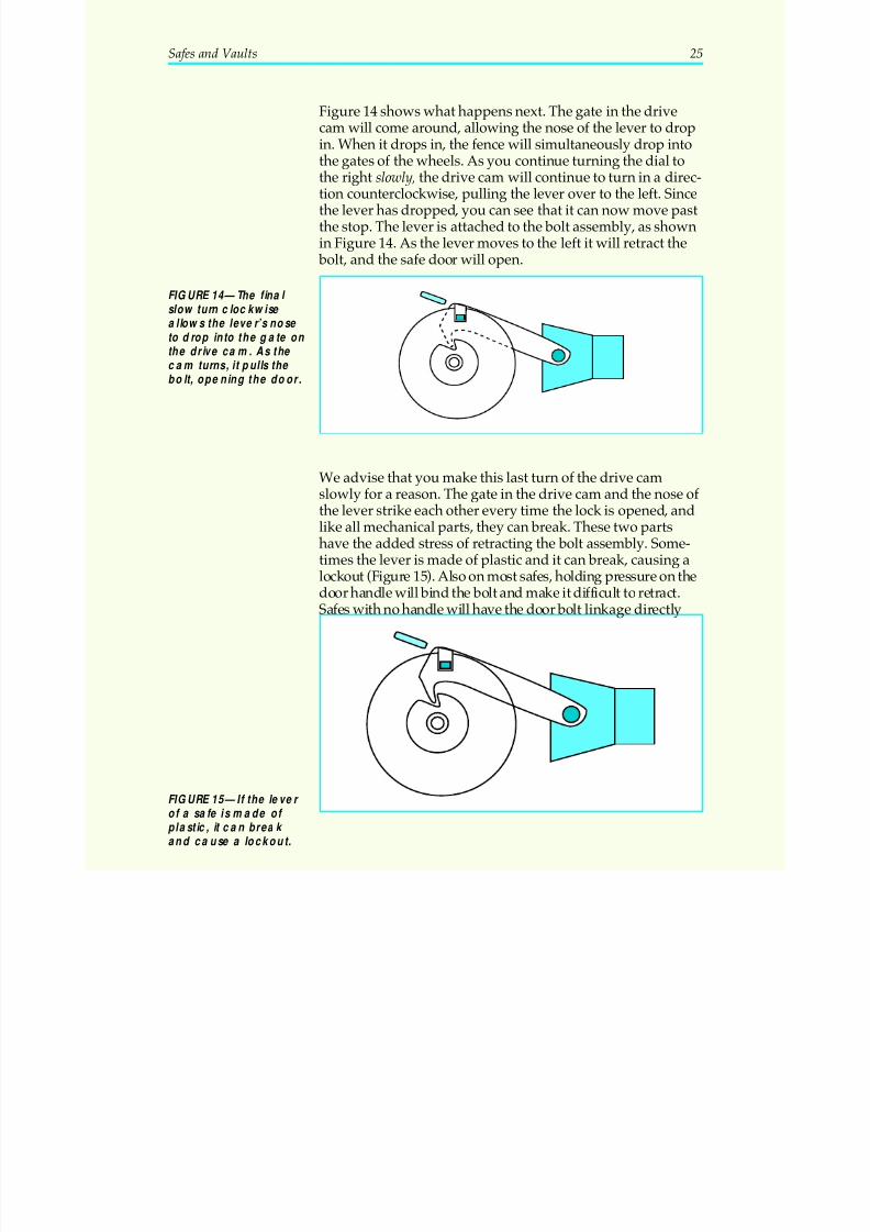
Figure 14 shows what happens next. The gate in the drivecam will come around, allowing the nose of the lever to dropin. When it drops in, the fence will simultaneously drop intothe gates of the wheels. As you continue turning the dial to
the right slowly, the drive cam will continue to turn in a direc-tion counterclockwise, pulling the lever over to the left. Sincethe lever has dropped, you can see that it can now move pastthe stop. The lever is attached to the bolt assembly, as shownin Figure 14. As the lever moves to the left it will retract the
bolt, and the safe door will open.
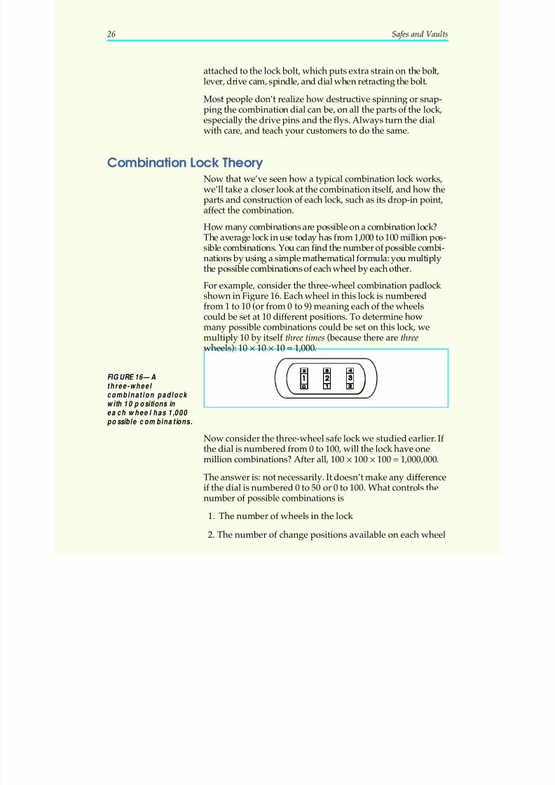
We advise that you make this last turn of the drive camslowly for a reason. The gate in the drive cam and the nose of the lever strike each other every time the lock is opened, andlike all mechanical parts, they can break. These two partshave the added stress of retracting the bolt assembly. Some-times the lever is made of plastic and it can break, causing alockout (Figure 15). Also on most safes, holding pressure on thedoor handle will bind the bolt and make it difficult to retract.Safes with no handle will have the door bolt linkage directly
Safes and Vaults 25
FIGURE 14—The final slow turn clockwise allows the lever’s nose to drop into the ga te on
the drive ca m. As the cam turns, it pulls the bolt, opening the door.
FIGURE 15—If the lever of a safe is made of plastic, it can break and cause a lockout.
5/12/2018 10 Safes and Vaults - slidepdf.com
http://slidepdf.com/reader/full/10-safes-and-vaults-55a35b88b6c27 30/103
attached to the lock bolt, which puts extra strain on the bolt,lever, drive cam, spindle, and dial when retracting the bolt.
Most people don’t realize how destructive spinning or snap-
ping the combination dial can be, on all the parts of the lock,especially the drive pins and the flys. Always turn the dialwith care, and teach your customers to do the same.
Combination Lock TheoryNow that we’ve seen how a typical combination lock works,we’ll take a closer look at the combination itself, and how theparts and construction of each lock, such as its drop-in point,affect the combination.
How many combinations are possible on a combination lock?The average lock in use today has from 1,000 to 100 million pos-sible combinations. You can find the number of possible combi-nations by using a simple mathematical formula: you multiplythe possible combinations of each wheel by each other.
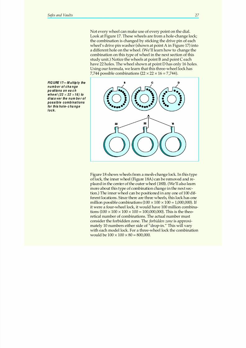
For example, consider the three-wheel combination padlock shown in Figure 16. Each wheel in this lock is numberedfrom 1 to 10 (or from 0 to 9) meaning each of the wheelscould be set at 10 different positions. To determine howmany possible combinations could be set on this lock, wemultiply 10 by itself three times (because there are threewheels): 10 10 10 1 000× × = , .
Now consider the three-wheel safe lock we studied earlier. If the dial is numbered from 0 to 100, will the lock have onemillion combinations? After all, 100 100 100 1 000 000× × = , , .
The answer is: not necessarily. It doesn’t make any differenceif the dial is numbered 0 to 50 or 0 to 100. What controls thenumber of possible combinations is
1. The number of wheels in the lock
2. The number of change positions available on each wheel
26 Safes and Vaults
FIGURE 16—Athree-wheel combination padlock with 10 positions in ea ch wheel has 1,000 possible combinations.
5/12/2018 10 Safes and Vaults - slidepdf.com
http://slidepdf.com/reader/full/10-safes-and-vaults-55a35b88b6c27 31/103
Not every wheel can make use of every point on the dial.Look at Figure 17. These wheels are from a hole-change lock;the combination is changed by sticking the drive pin of eachwheel’s drive pin washer (shown at point A in Figure 17) into
a different hole on the wheel. (We’ll learn how to change thecombination on this type of wheel in the next section of thisstudy unit.) Notice the wheels at point B and point C eachhave 22 holes. The wheel shown at point D has only 16 holes.Using our formula, we learn that this three-wheel lock has7,744 possible combinations (22 22 16 7 744× × = , ).
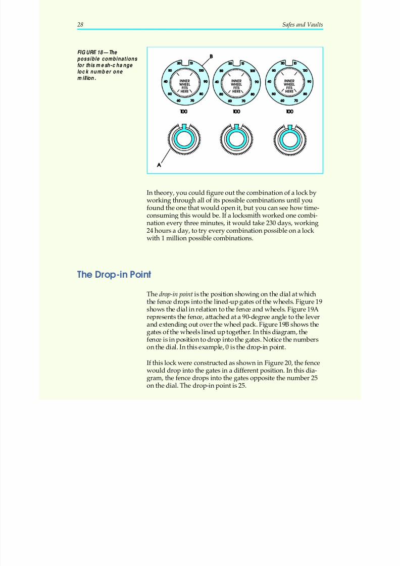
Figure 18 shows wheels from a mesh-change lock. In this typeof lock, the inner wheel (Figure 18A) can be removed and re-placed in the center of the outer wheel (18B). (We’ll also learnmore about this type of combination change in the next sec-tion.) The inner wheel can be positioned in any one of 100 dif -
ferent locations. Since there are three wheels, this lock has onemillion possible combinations (100 100 100 1 000 000× × = , , ). If it were a four-wheel lock, it would have 100 million combina-tions (100 100 100 100 100 000 000× × × = , , ). This is the theo-retical number of combinations. The actual number mustconsider the forbidden zone. The forbidden zone is approxi-mately 10 numbers either side of “drop-in.” This will varywith each model lock. For a three-wheel lock the combinationwould be 100 100 80 800 000× × = , .
Safes and Vaults 27
FIGURE 17—Multiply the number of change positions on each wheel ( 22 22 16 × × ) to
discover the number of possible combinations for this hole-change lock.
5/12/2018 10 Safes and Vaults - slidepdf.com
http://slidepdf.com/reader/full/10-safes-and-vaults-55a35b88b6c27 32/103
In theory, you could figure out the combination of a lock byworking through all of its possible combinations until youfound the one that would open it, but you can see how time-consuming this would be. If a locksmith worked one combi-nation every three minutes, it would take 230 days, working24 hours a day, to try every combination possible on a lock
with 1 million possible combinations.
The Drop-in Point
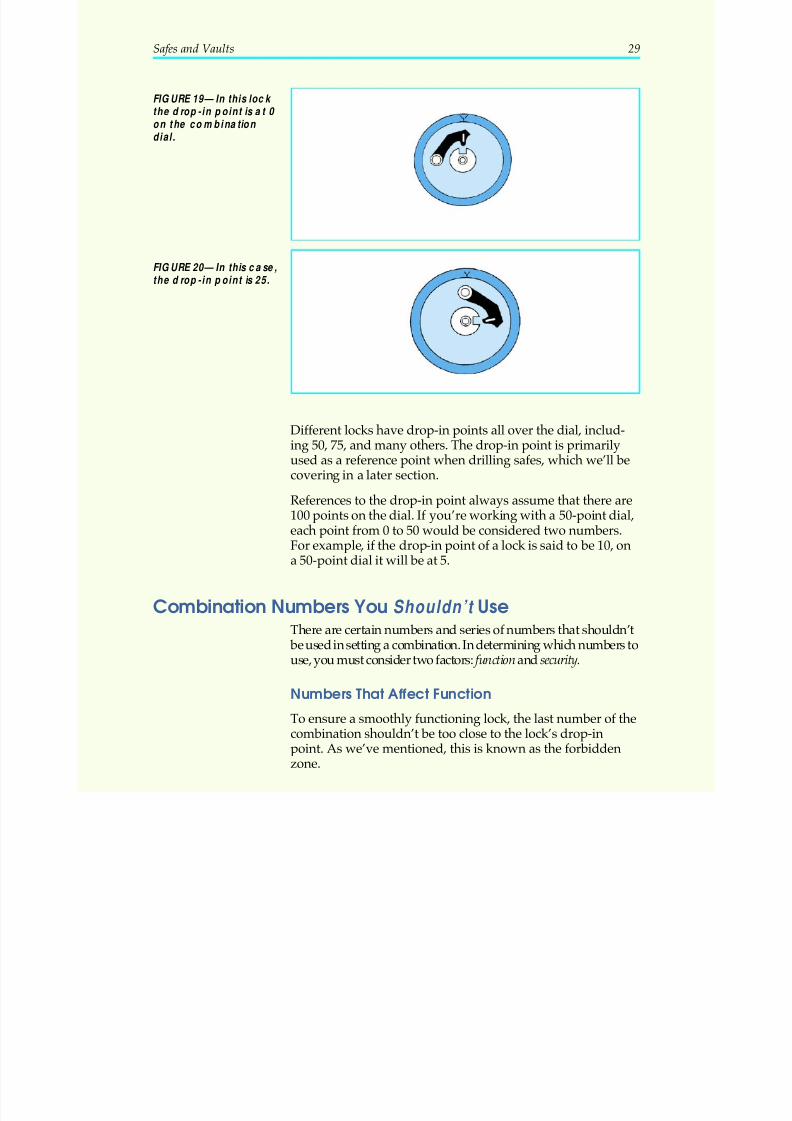
The drop-in point is the position showing on the dial at whichthe fence drops into the lined-up gates of the wheels. Figure 19shows the dial in relation to the fence and wheels. Figure 19A
represents the fence, attached at a 90-degree angle to the leverand extending out over the wheel pack. Figure 19B shows thegates of the wheels lined up together. In this diagram, thefence is in position to drop into the gates. Notice the numberson the dial. In this example, 0 is the drop-in point.
If this lock were constructed as shown in Figure 20, the fencewould drop into the gates in a different position. In this dia-gram, the fence drops into the gates opposite the number 25on the dial. The drop-in point is 25.
28 Safes and Vaults
INNER WHEEL
FITS
HERE
INNER WHEEL
FITS
HERE
INNER WHEEL
FITS
HERE
FIGURE 18—The possible combinations for this mesh-change lock number one
million.
5/12/2018 10 Safes and Vaults - slidepdf.com
http://slidepdf.com/reader/full/10-safes-and-vaults-55a35b88b6c27 33/103
Different locks have drop-in points all over the dial, includ-ing 50, 75, and many others. The drop-in point is primarilyused as a reference point when drilling safes, which we’ll be
covering in a later section.
References to the drop-in point always assume that there are100 points on the dial. If you’re working with a 50-point dial,each point from 0 to 50 would be considered two numbers.For example, if the drop-in point of a lock is said to be 10, ona 50-point dial it will be at 5.
Combination Numbers You Shouldn’t Use
There are certain numbers and series of numbers that shouldn’t be used in setting a combination. In determining which numbers touse, you must consider two factors: function and security.
Numbers That Affect Function
To ensure a smoothly functioning lock, the last number of thecombination shouldn’t be too close to the lock’s drop-inpoint. As we’ve mentioned, this is known as the forbiddenzone.
Safes and Vaults 29
FIGURE 19—In this lock the drop-in point is at 0 on the combination dial.
FIGURE 20—In this ca se,the drop-in point is 25.
5/12/2018 10 Safes and Vaults - slidepdf.com
http://slidepdf.com/reader/full/10-safes-and-vaults-55a35b88b6c27 34/103
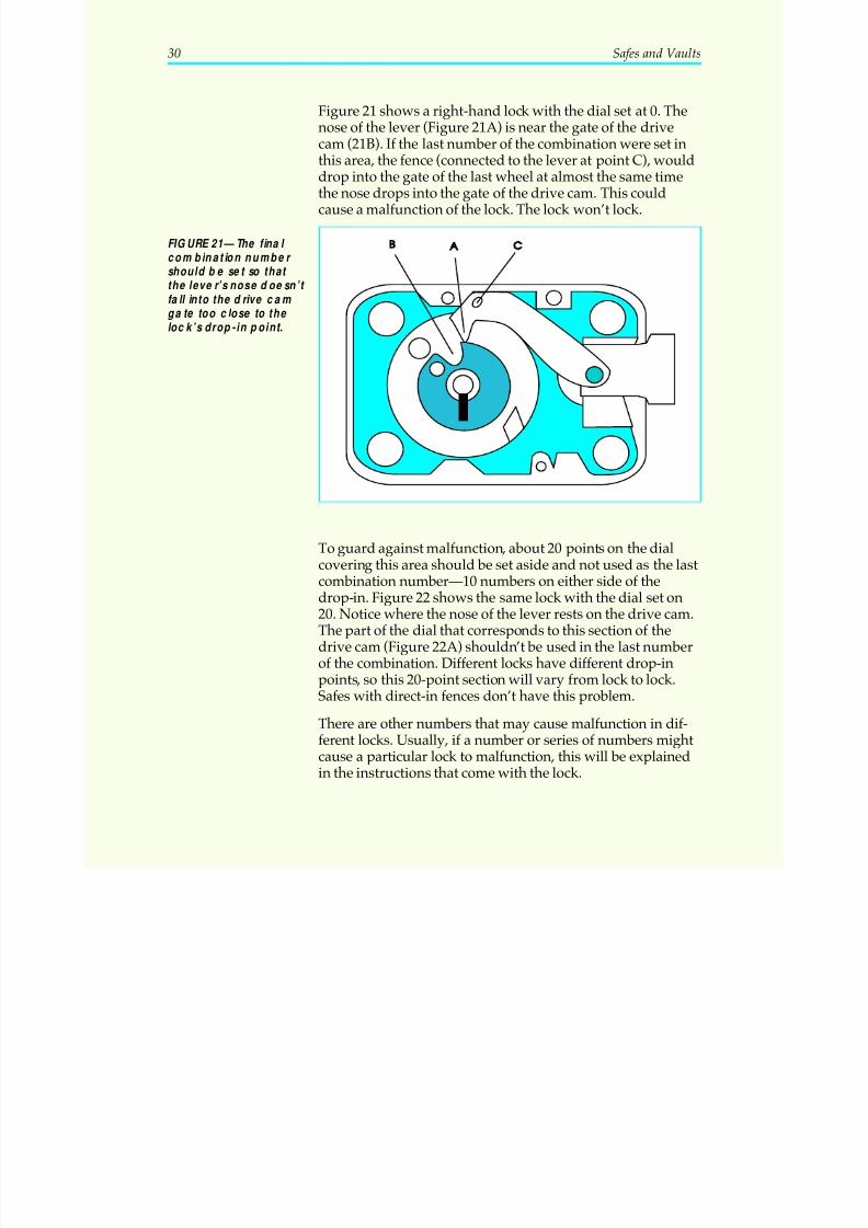
Figure 21 shows a right-hand lock with the dial set at 0. Thenose of the lever (Figure 21A) is near the gate of the drivecam (21B). If the last number of the combination were set inthis area, the fence (connected to the lever at point C), would
drop into the gate of the last wheel at almost the same timethe nose drops into the gate of the drive cam. This couldcause a malfunction of the lock. The lock won’t lock.
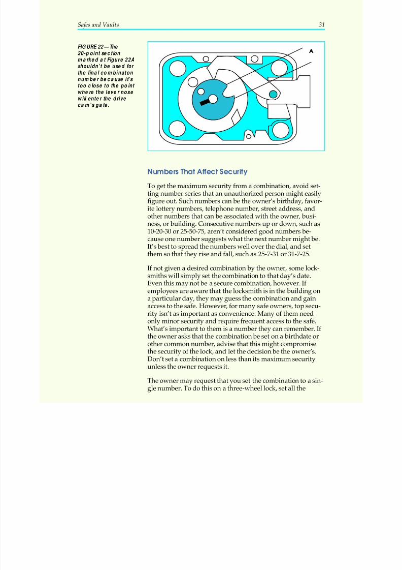
To guard against malfunction, about 20 points on the dialcovering this area should be set aside and not used as the lastcombination number—10 numbers on either side of thedrop-in. Figure 22 shows the same lock with the dial set on20. Notice where the nose of the lever rests on the drive cam.The part of the dial that corresponds to this section of thedrive cam (Figure 22A) shouldn’t be used in the last numberof the combination. Different locks have different drop-inpoints, so this 20-point section will vary from lock to lock.
Safes with direct-in fences don’t have this problem.
There are other numbers that may cause malfunction in dif-ferent locks. Usually, if a number or series of numbers mightcause a particular lock to malfunction, this will be explainedin the instructions that come with the lock.
30 Safes and Vaults
FIGURE 21—The final combination number should be set so that the lever’s nose doesn’t fall into the drive cam gate too close to the lock’s drop- in point.
5/12/2018 10 Safes and Vaults - slidepdf.com
http://slidepdf.com/reader/full/10-safes-and-vaults-55a35b88b6c27 35/103
Numbers That Affect Security
To get the maximum security from a combination, avoid set-ting number series that an unauthorized person might easilyfigure out. Such numbers can be the owner’s birthday, favor-ite lottery numbers, telephone number, street address, andother numbers that can be associated with the owner, busi-ness, or building. Consecutive numbers up or down, such as10-20-30 or 25-50-75, aren’t considered good numbers be-
cause one number suggests what the next number might be.It’s best to spread the numbers well over the dial, and setthem so that they rise and fall, such as 25-7-31 or 31-7-25.
If not given a desired combination by the owner, some lock-smiths will simply set the combination to that day’s date.Even this may not be a secure combination, however. If employees are aware that the locksmith is in the building ona particular day, they may guess the combination and gainaccess to the safe. However, for many safe owners, top secu-rity isn’t as important as convenience. Many of them need
only minor security and require frequent access to the safe.What’s important to them is a number they can remember. If the owner asks that the combination be set on a birthdate orother common number, advise that this might compromisethe security of the lock, and let the decision be the owner’s.Don’t set a combination on less than its maximum securityunless the owner requests it.
The owner may request that you set the combination to a sin-gle number. To do this on a three-wheel lock, set all the
Safes and Vaults 31
FIGURE 22—The 20-point section marked a t Figure 22Ashouldn’t be used for the final combinaton
number because it’s too close to the point where the lever nose will enter the drive ca m’s gate.
5/12/2018 10 Safes and Vaults - slidepdf.com
http://slidepdf.com/reader/full/10-safes-and-vaults-55a35b88b6c27 36/103
wheels to the same number. To open the lock, turn the dialfour times in the same direction and stop on the combinationnumber. Turn in the opposite direction slowly until the boltretracts. If it’s a right-hand lock, you’ll turn the dial four
times to the left and stop on the combination number, thenturn right slowly until the bolt retracts.
To set the combination of a three-wheel lock to open on twonumbers, set the No. 1 and No. 2 wheels to the same numberand the No. 3 wheel to the second number. Remember thatthe No. 3 wheel is always the wheel next to the drive cam.Work the combination by turning the dial four times in thesame direction and stop on the first combination number.Then turn in the opposite direction until the second number
reaches the opening index, the second time it comes around.Then, turn the dial back in the opposite direction slowly untilthe fence drops into the gates and the bolt retracts.
Drive Cam Gating and Location
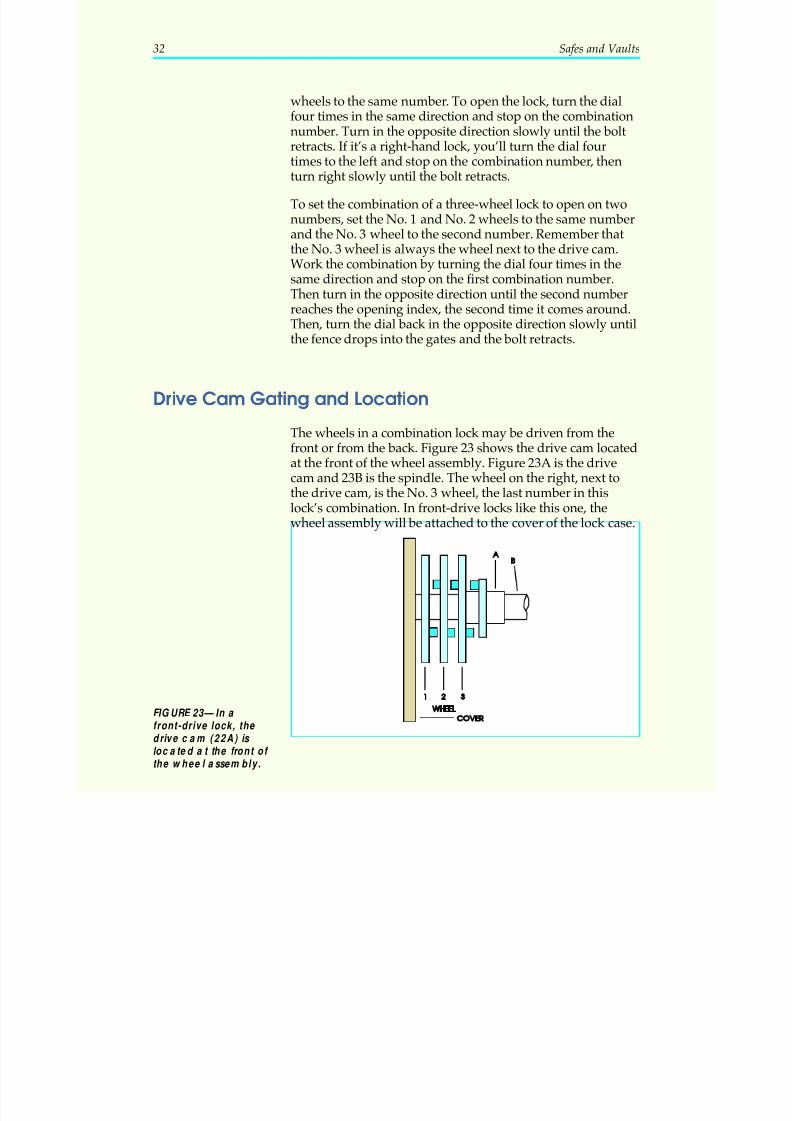
The wheels in a combination lock may be driven from thefront or from the back. Figure 23 shows the drive cam locatedat the front of the wheel assembly. Figure 23A is the drive
cam and 23B is the spindle. The wheel on the right, next tothe drive cam, is the No. 3 wheel, the last number in thislock’s combination. In front-drive locks like this one, thewheel assembly will be attached to the cover of the lock case.
32 Safes and Vaults
FIGURE 23—In a front-drive lock, the drive c am (22A) is located a t the front of the wheel assembly.
5/12/2018 10 Safes and Vaults - slidepdf.com
http://slidepdf.com/reader/full/10-safes-and-vaults-55a35b88b6c27 37/103
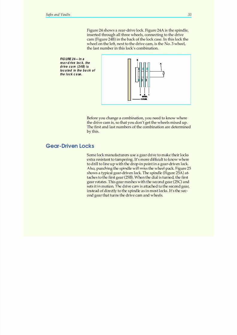
Figure 24 shows a rear-drive lock. Figure 24A is the spindle,inserted through all three wheels, connecting to the drivecam (Figure 24B) in the back of the lock case. In this lock thewheel on the left, next to the drive cam, is the No. 3 wheel,
the last number in this lock’s combination.
Before you change a combination, you need to know wherethe drive cam is, so that you don’t get the wheels mixed up.The first and last numbers of the combination are determined
by this.
Gear-Driven Locks
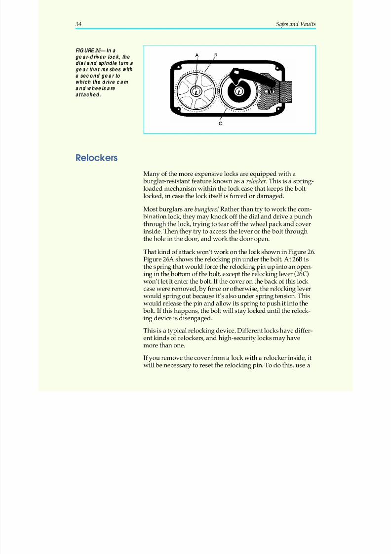
Some lock manufacturers use a gear drive to make their locksextra resistant to tampering. It’s more difficult to know whereto drill to line up with the drop-in point in a gear-driven lock.Also, punching the spindle will miss the wheel pack. Figure 25shows a typical gear-driven lock. The spindle (Figure 25A) at-taches to the first gear (25B). When the dial is turned, the firstgear rotates. This gear meshes with the second gear (25C) andsets it in motion. The drive cam is attached to the second gear,instead of directly to the spindle as in most locks. It’s the sec-ond gear that turns the drive cam and wheels.
Safes and Vaults 33
FIGURE 24—In a rea r-drive lock, the drive c am (24B) is loca ted in the ba ck of the lock case.
5/12/2018 10 Safes and Vaults - slidepdf.com
http://slidepdf.com/reader/full/10-safes-and-vaults-55a35b88b6c27 38/103
Relockers
Many of the more expensive locks are equipped with a burglar-resistant feature known as a relocker. This is a spring-loaded mechanism within the lock case that keeps the boltlocked, in case the lock itself is forced or damaged.
Most burglars are bunglers! Rather than try to work the com- bination lock, they may knock off the dial and drive a punchthrough the lock, trying to tear off the wheel pack and cover
inside. Then they try to access the lever or the bolt throughthe hole in the door, and work the door open.
That kind of attack won’t work on the lock shown in Figure 26.Figure 26A shows the relocking pin under the bolt. At 26B isthe spring that would force the relocking pin up into an open-ing in the bottom of the bolt, except the relocking lever (26C)won’t let it enter the bolt. If the cover on the back of this lock case were removed, by force or otherwise, the relocking leverwould spring out because it’s also under spring tension. Thiswould release the pin and allow its spring to push it into the
bolt. If this happens, the bolt will stay locked until the relock-ing device is disengaged.
This is a typical relocking device. Different locks have differ-ent kinds of relockers, and high-security locks may havemore than one.
If you remove the cover from a lock with a relocker inside, itwill be necessary to reset the relocking pin. To do this, use a
34 Safes and Vaults
FIGURE 25—In a gear-driven lock, the dial and spindle turn a gear that meshes with
a second gear to which the drive cam and wheels are attached.
5/12/2018 10 Safes and Vaults - slidepdf.com
http://slidepdf.com/reader/full/10-safes-and-vaults-55a35b88b6c27 39/103
small screwdriver to depress the spring, and push in on therelocking lever.
Besides a relocker within the lock, some burglary-resistivesafes will have a separate relocker within the door. Some of these consist of bolts suspended on a heat-sensitive wire. If heat from a grinder or blowtorch is applied to the safe, thewire melts and the bolts drop or spring into the doorjamb,keeping it locked even if the lock or hinges are burned off.
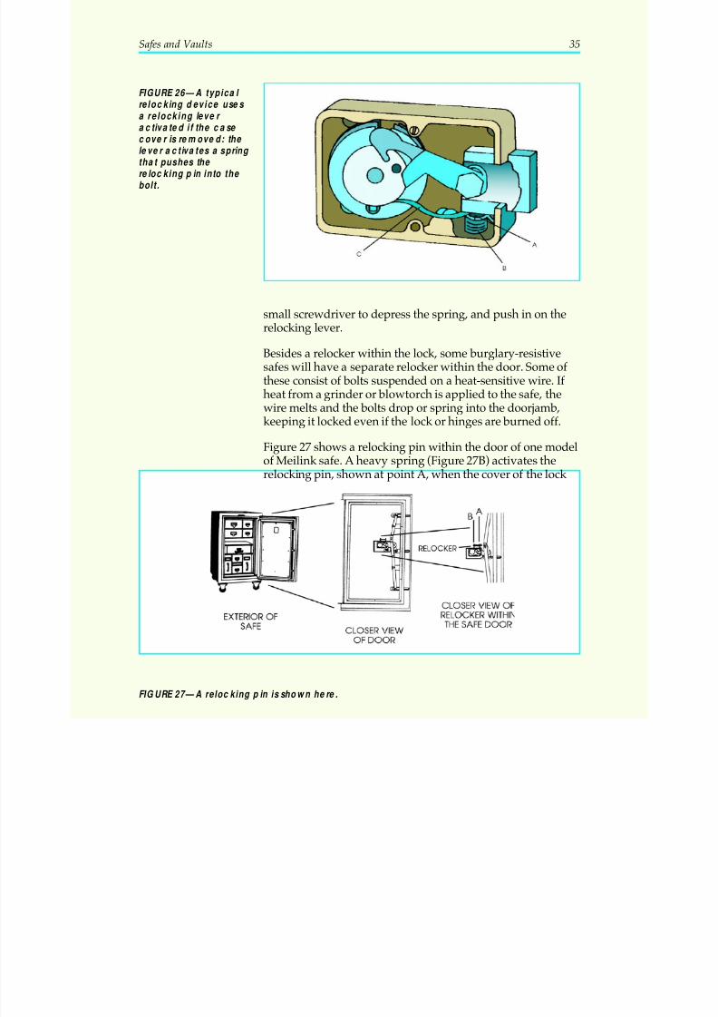
Figure 27 shows a relocking pin within the door of one modelof Meilink safe. A heavy spring (Figure 27B) activates therelocking pin, shown at point A, when the cover of the lock
Safes and Vaults 35
FIGURE 26—A typical relocking device uses a relocking lever activated if the case
cover is removed: the lever activates a spring that pushes the relocking pin into the bolt.
FIGURE 27—A relocking pin is shown here.

5/12/2018 10 Safes and Vaults - slidepdf.com
http://slidepdf.com/reader/full/10-safes-and-vaults-55a35b88b6c27 40/103
case is moved or knocked out. You can see that in Figure 27,the cover is missing and the relocking pin has been activated.Notice how the locking mechanism of the door strikes thispin, thus preventing the bolts from being retracted. This is so
that even if the combination lock and its internal relockingpin are defeated, the external relocker in the door will keepthe door locked.
36 Safes and Vaults
5/12/2018 10 Safes and Vaults - slidepdf.com
http://slidepdf.com/reader/full/10-safes-and-vaults-55a35b88b6c27 41/103
Safes and Vaults 37
Locking It Up! 2
1. What is the purpose of the spline key? Do all locks have one?
_____________________________________________________________________
_____________________________________________________________________
2. What do fire-resistive safes have within them that burglary-resistive
safes usually don’t have?
_____________________________________________________________________
_____________________________________________________________________
3. How do you determine the “hand” of the lock?
_____________________________________________________________________
_____________________________________________________________________
4. Is the wheel next to the drive cam referred to as the last wheel or thefirst wheel? Does it correspond to the last number or the first numberof the combination?
_____________________________________________________________________
_____________________________________________________________________
5. What two things tell you how many combinations are possible onany given lock?
_____________________________________________________________________
_____________________________________________________________________
Check your answers with those on page 91.
5/12/2018 10 Safes and Vaults - slidepdf.com
http://slidepdf.com/reader/full/10-safes-and-vaults-55a35b88b6c27 42/103
CHANGING A SAFECOMBINATION
The Most Often Requested Service
The most common request a locksmith gets from a safeowner is to change the combination of the lock. At the sametime that the combination is changed, the locksmith generallyservices the lock, making sure its working parts move freely,replacing worn or broken parts, and cleaning out dirt and de-
bris that may jam the lock. This section of your text will coverthe basics of changing a combination. The next section willdeal with servicing the lock.
When it comes to combination changing, locks fall into twomain categories: hand-changing and key-changing. Hand-changing locks are changed manually. There are three majorkinds of hand-changing locks: hole-type, screw-type, and mesh-type. As their name suggests, key-changing locks are changedonly with a special key. We’ll look at the different types of hand-changing locks first.
A reminder: As you begin to change combinations on locksand service them, always test your work at least five timeswith the safe door open. Never assume that you’ve followedevery step, lock the door, and then see if you’ve done it cor-rectly! Even if you make the combination change correctly,there may be a mechanical malfunction that keeps it fromworking, which you won’t be able to see unless you test thelock before closing the door. After you’ve tested the lock,have your customer test it too, while the door is still open. Thatway, if it should lock up when the customer next uses it, thecustomer will know it was working properly when the lock-smith was done with it. The second reason for the customer
operating the lock at least three times with the door open isthat it’s a good check on the locksmith’s work.
Hole-Type Locks
Hole-type wheels are typical of many inexpensive locks.They’re often found on chests, locker boxes, and some of thesmaller inexpensive safes. Looking at Figure 28, you’ll notice
38 Safes and Vaults
5/12/2018 10 Safes and Vaults - slidepdf.com
http://slidepdf.com/reader/full/10-safes-and-vaults-55a35b88b6c27 43/103
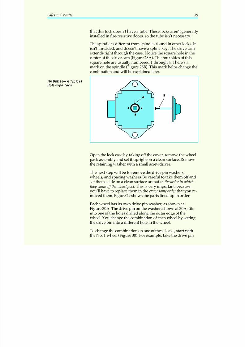
that this lock doesn’t have a tube. These locks aren’t generallyinstalled in fire-resistive doors, so the tube isn’t necessary.
The spindle is different from spindles found in other locks. It
isn’t threaded, and doesn’t have a spline key. The drive camextends right through the case. Notice the square hole in thecenter of the drive cam (Figure 28A). The four sides of thissquare hole are usually numbered 1 through 4. There’s amark on the spindle (Figure 28B). This mark helps change thecombination and will be explained later.
Open the lock case by taking off the cover, remove the wheelpack assembly and set it upright on a clean surface. Removethe retaining washer with a small screwdriver.
The next step will be to remove the drive pin washers,wheels, and spacing washers. Be careful to take them off andset them aside on a clean surface or mat in the order in whichthey came off the wheel post. This is very important, becauseyou’ll have to replace them in the exact same order that you re-
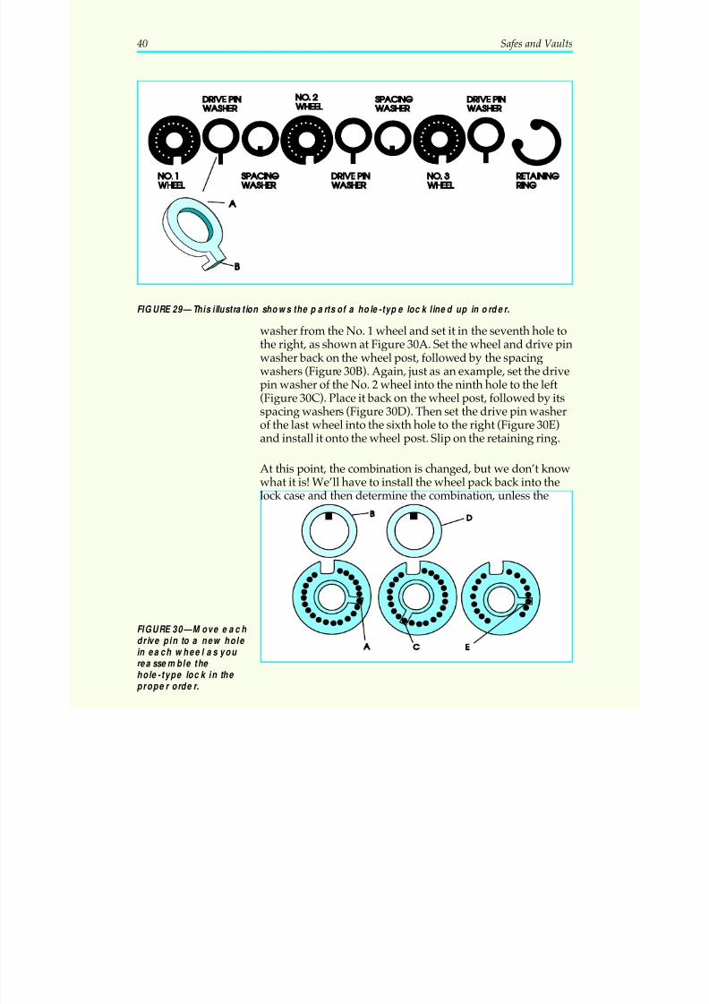
moved them. Figure 29 shows the parts lined up in order.
Each wheel has its own drive pin washer, as shown atFigure 30A. The drive pin on the washer, shown at 30A, fitsinto one of the holes drilled along the outer edge of thewheel. You change the combination of each wheel by settingthe drive pin into a different hole in the wheel.
To change the combination on one of these locks, start withthe No. 1 wheel (Figure 30). For example, take the drive pin
Safes and Vaults 39
FIGURE 28—A Typical Hole- type Lock
5/12/2018 10 Safes and Vaults - slidepdf.com
http://slidepdf.com/reader/full/10-safes-and-vaults-55a35b88b6c27 44/103
washer from the No. 1 wheel and set it in the seventh hole tothe right, as shown at Figure 30A. Set the wheel and drive pinwasher back on the wheel post, followed by the spacingwashers (Figure 30B). Again, just as an example, set the drivepin washer of the No. 2 wheel into the ninth hole to the left(Figure 30C). Place it back on the wheel post, followed by itsspacing washers (Figure 30D). Then set the drive pin washer
of the last wheel into the sixth hole to the right (Figure 30E)and install it onto the wheel post. Slip on the retaining ring.
At this point, the combination is changed, but we don’t knowwhat it is! We’ll have to install the wheel pack back into thelock case and then determine the combination, unless the
40 Safes and Vaults
FIGURE 29—This illustration shows the parts of a hole-type lock lined up in order.
FIGURE 30—Move each drive pin to a new hole in ea ch wheel as you reassemble the hole-type lock in the proper order.
5/12/2018 10 Safes and Vaults - slidepdf.com
http://slidepdf.com/reader/full/10-safes-and-vaults-55a35b88b6c27 45/103
holes in the wheels have numbers on them. If they do, you al-ready know the combination numbers. If they aren’t num-
bered, you must determine the combination as follows.
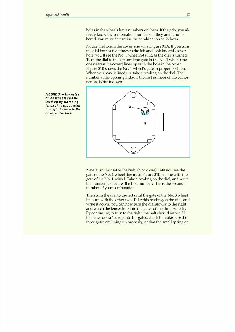
Notice the hole in the cover, shown at Figure 31A. If you turnthe dial four or five times to the left and look into this coverhole, you’ll see the No. 1 wheel rotating as the dial is turned.Turn the dial to the left until the gate in the No. 1 wheel (theone nearest the cover) lines up with the hole in the cover.Figure 31B shows the No. 1 wheel’s gate in proper position.When you have it lined up, take a reading on the dial. Thenumber at the opening index is the first number of the combi-nation. Write it down.
Next, turn the dial to the right (clockwise) until you see thegate of the No. 2 wheel line up at Figure 31B, in line with thegate of the No. 1 wheel. Take a reading on the dial, and writethe number just below the first number. This is the second
number of your combination.
Then turn the dial to the left until the gate of the No. 3 wheellines up with the other two. Take this reading on the dial, andwrite it down. You can now turn the dial slowly to the rightand watch the fence drop into the gates of the three wheels.By continuing to turn to the right, the bolt should retract. If the fence doesn’t drop into the gates, check to make sure thethree gates are lining up properly, or that the small spring on
Safes and Vaults 41
FIGURE 31—The ga tes of the wheels can be lined up by wa tching for each in succession through the hole in the cover of the lock.
5/12/2018 10 Safes and Vaults - slidepdf.com
http://slidepdf.com/reader/full/10-safes-and-vaults-55a35b88b6c27 46/103
the lever hasn’t come loose. This spring forces the leveragainst the wheels at all times.
You should now be able to work the combination from the
front, without looking into the cover hole. Test it from thefront with the door open. Remember the procedure for open-ing a three-wheel, right-hand lock:
Step 1: Turn the dial left four times, stopping at the firstnumber.
Step 2: Turn the dial right three times, stopping at the secondnumber the third time it reaches the opening index.
Step 3: Turn the dial left two times, stopping on the thirdnumber the second time it reaches the opening index.
Step 4: Turn the dial right slowly until the lock opens.
Always work the combination at least five times to be sure thewheels turn freely, without binding on each other. Try work-ing the combination one-half number more or less of each cor-rect number; this tests the proper reading of the combination.
There’s a shortcut to changing the combination on this type of lock. It only works if the spindle is the square-hole type (thismethod won’t work with the round spindle seen in previous ex-
amples). With the shortcut, you can set one of four different com- binations without making any changes in the wheels themselves.
First, loosen the two nuts holding the lock to the dial assem- bly. Then rotate the dial one quarter turn so the mark on thespindle is in the hole in the drive cam on the side marked“2.” You can now read this new combination through thecover hole, as in the previous example, or you can figure itout mathematically.
Once you know one combination, you can figure out in ad-
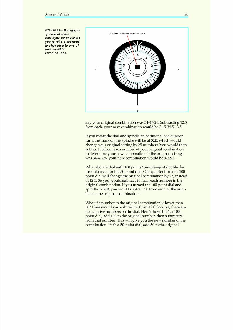
vance the other three, and invite your customer to choose one.Figure 32 shows what happens when you turn the dial onequarter turn. Because the spindle is square, you can divide thedial into four equal sections. The dial in Figure 32 has 50 num-
bers, and we’ll assume for this example that your first settingwas with the spindle mark at 0. If you rotate the dial and spin-dle one quarter turn to the right, you’ll change your setting by12.5 numbers, as shown at point A in Figure 32. You wouldsubtract 12.5 from each of the numbers of your original combi-nation to determine what your new combination is.
42 Safes and Vaults
5/12/2018 10 Safes and Vaults - slidepdf.com
http://slidepdf.com/reader/full/10-safes-and-vaults-55a35b88b6c27 47/103
Say your original combination was 34-47-26. Subtracting 12.5from each, your new combination would be 21.5-34.5-13.5.
If you rotate the dial and spindle an additional one quarter
turn, the mark on the spindle will be at 32B, which wouldchange your original setting by 25 numbers. You would thensubtract 25 from each number of your original combinationto determine your new combination. If the original settingwas 34-47-26, your new combination would be 9-22-1.
What about a dial with 100 points? Simple—just double theformula used for the 50-point dial. One quarter turn of a 100-point dial will change the original combination by 25, insteadof 12.5. So you would subtract 25 from each number in the
original combination. If you turned the 100-point dial andspindle to 32B, you would subtract 50 from each of the num- bers in the original combination.
What if a number in the original combination is lower than50? How would you subtract 50 from it? Of course, there areno negative numbers on the dial. Here’s how: If it’s a 100-point dial, add 100 to the original number, then subtract 50from that number. This will give you the new number of thecombination. If it’s a 50-point dial, add 50 to the original
Safes and Vaults 43
05
1 0
1 5
2 0
2 5 3 0
3 5
4 0
4 5
C A
B
POSITION OF SPINDLE INSIDE THE LOCK
FIGURE 32—The square spindle of some hole-type locks allows you to take a shortcut
to changing to one of four possible combinations.
5/12/2018 10 Safes and Vaults - slidepdf.com
http://slidepdf.com/reader/full/10-safes-and-vaults-55a35b88b6c27 48/103
number, then subtract 25 to find the new number of the com- bination. To demonstrate this, look again at Figure 32.
Say you want to turn this 50-point dial and spindle to point
32B, and your original combination is 34-47-20. You alreadyknow that you must subtract 25 from 34 and from 47 to findthe first two numbers of the new combination: 9 and 22. Butyou can’t subtract 25 from 20. Therefore, you add 50 (thenumber of points on the dial) to the original number (20),then subtract 25.
50 + 20 = 7070 – 25 = 45
The new combination will be 9-22-45.
Figure 32C shows the fourth possible combination point,three quarter turns from the original setting at 0. With a littlepractice you’ll easily figure out all four possible combina-tions. But as always, test the new combination at least fivetimes with the door open. Make sure your new combinationwill actually open the lock, and that the lock is functioningsmoothly, before you put it back in your customer’s hands.
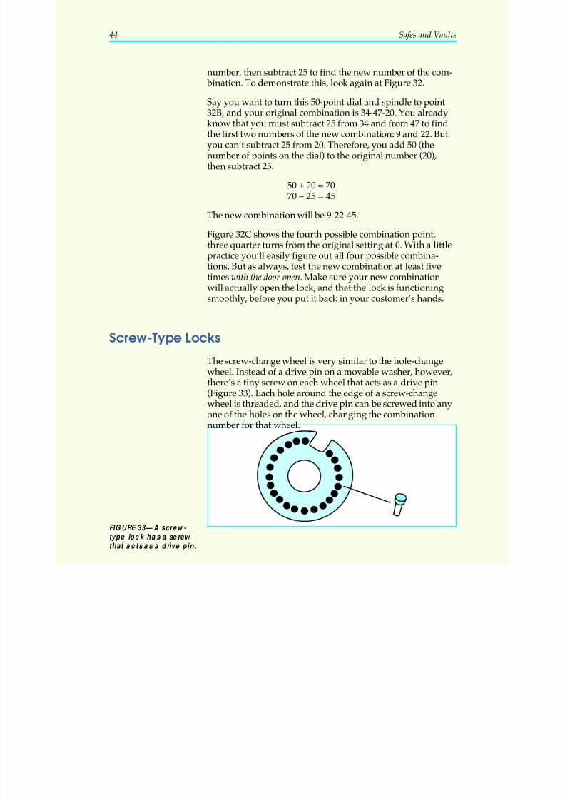
Screw-Type LocksThe screw-change wheel is very similar to the hole-changewheel. Instead of a drive pin on a movable washer, however,there’s a tiny screw on each wheel that acts as a drive pin(Figure 33). Each hole around the edge of a screw-changewheel is threaded, and the drive pin can be screwed into anyone of the holes on the wheel, changing the combinationnumber for that wheel.
44 Safes and Vaults
FIGURE 33—A screw- type lock has a screw that acts as a drive pin.
5/12/2018 10 Safes and Vaults - slidepdf.com
http://slidepdf.com/reader/full/10-safes-and-vaults-55a35b88b6c27 49/103
Mesh-Type Locks
We saw in a previous example that the mesh-type wheel is
made of two parts, an inner wheel and an outer wheel, bothof which have teeth that mesh to hold them together.
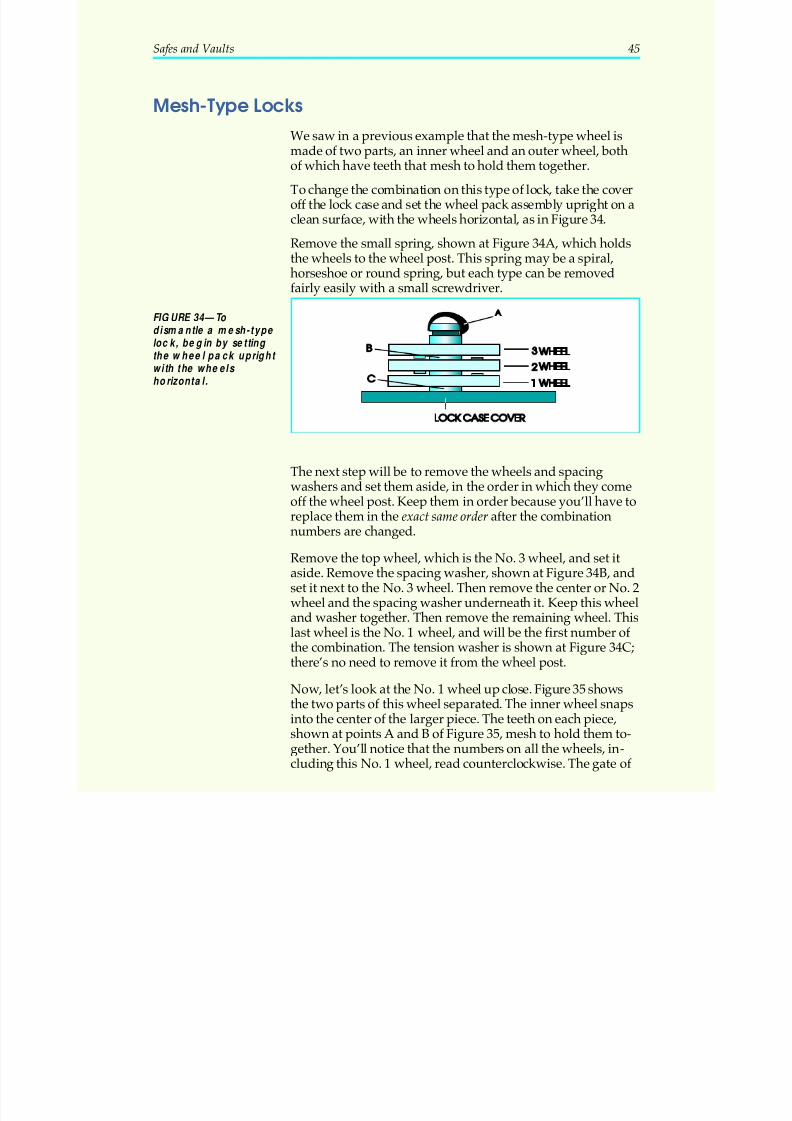
To change the combination on this type of lock, take the coveroff the lock case and set the wheel pack assembly upright on aclean surface, with the wheels horizontal, as in Figure 34.
Remove the small spring, shown at Figure 34A, which holdsthe wheels to the wheel post. This spring may be a spiral,horseshoe or round spring, but each type can be removedfairly easily with a small screwdriver.
The next step will be to remove the wheels and spacingwashers and set them aside, in the order in which they comeoff the wheel post. Keep them in order because you’ll have toreplace them in the exact same order after the combinationnumbers are changed.
Remove the top wheel, which is the No. 3 wheel, and set itaside. Remove the spacing washer, shown at Figure 34B, andset it next to the No. 3 wheel. Then remove the center or No. 2wheel and the spacing washer underneath it. Keep this wheeland washer together. Then remove the remaining wheel. This
last wheel is the No. 1 wheel, and will be the first number of the combination. The tension washer is shown at Figure 34C;there’s no need to remove it from the wheel post.
Now, let’s look at the No. 1 wheel up close. Figure 35 showsthe two parts of this wheel separated. The inner wheel snapsinto the center of the larger piece. The teeth on each piece,shown at points A and B of Figure 35, mesh to hold them to-gether. You’ll notice that the numbers on all the wheels, in-cluding this No. 1 wheel, read counterclockwise. The gate of
Safes and Vaults 45
FIGURE 34—To dismantle a mesh-type lock, begin by setting the wheel pack upright with the wheels horizontal.
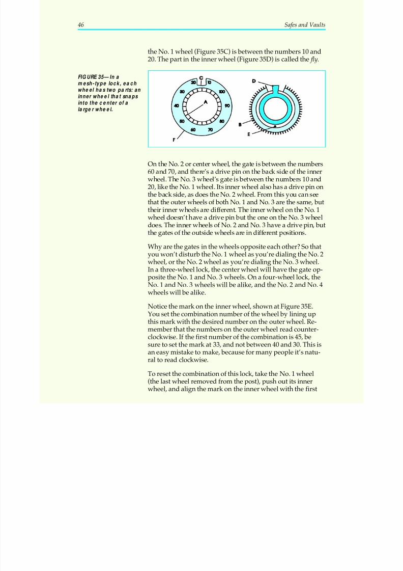
5/12/2018 10 Safes and Vaults - slidepdf.com
http://slidepdf.com/reader/full/10-safes-and-vaults-55a35b88b6c27 50/103
the No. 1 wheel (Figure 35C) is between the numbers 10 and20. The part in the inner wheel (Figure 35D) is called the fly.
On the No. 2 or center wheel, the gate is between the numbers60 and 70, and there’s a drive pin on the back side of the innerwheel. The No. 3 wheel’s gate is between the numbers 10 and20, like the No. 1 wheel. Its inner wheel also has a drive pin onthe back side, as does the No. 2 wheel. From this you can seethat the outer wheels of both No. 1 and No. 3 are the same, buttheir inner wheels are different. The inner wheel on the No. 1wheel doesn’t have a drive pin but the one on the No. 3 wheeldoes. The inner wheels of No. 2 and No. 3 have a drive pin, butthe gates of the outside wheels are in different positions.
Why are the gates in the wheels opposite each other? So thatyou won’t disturb the No. 1 wheel as you’re dialing the No. 2wheel, or the No. 2 wheel as you’re dialing the No. 3 wheel.In a three-wheel lock, the center wheel will have the gate op-posite the No. 1 and No. 3 wheels. On a four-wheel lock, theNo. 1 and No. 3 wheels will be alike, and the No. 2 and No. 4wheels will be alike.
Notice the mark on the inner wheel, shown at Figure 35E.You set the combination number of the wheel by lining up
this mark with the desired number on the outer wheel. Re-member that the numbers on the outer wheel read counter-clockwise. If the first number of the combination is 45, besure to set the mark at 33, and not between 40 and 30. This isan easy mistake to make, because for many people it’s natu-ral to read clockwise.
To reset the combination of this lock, take the No. 1 wheel(the last wheel removed from the post), push out its innerwheel, and align the mark on the inner wheel with the first
46 Safes and Vaults
FIGURE 35—In a mesh-type lock, eac h wheel has two parts: an inner wheel that snaps into the center of a larger wheel.
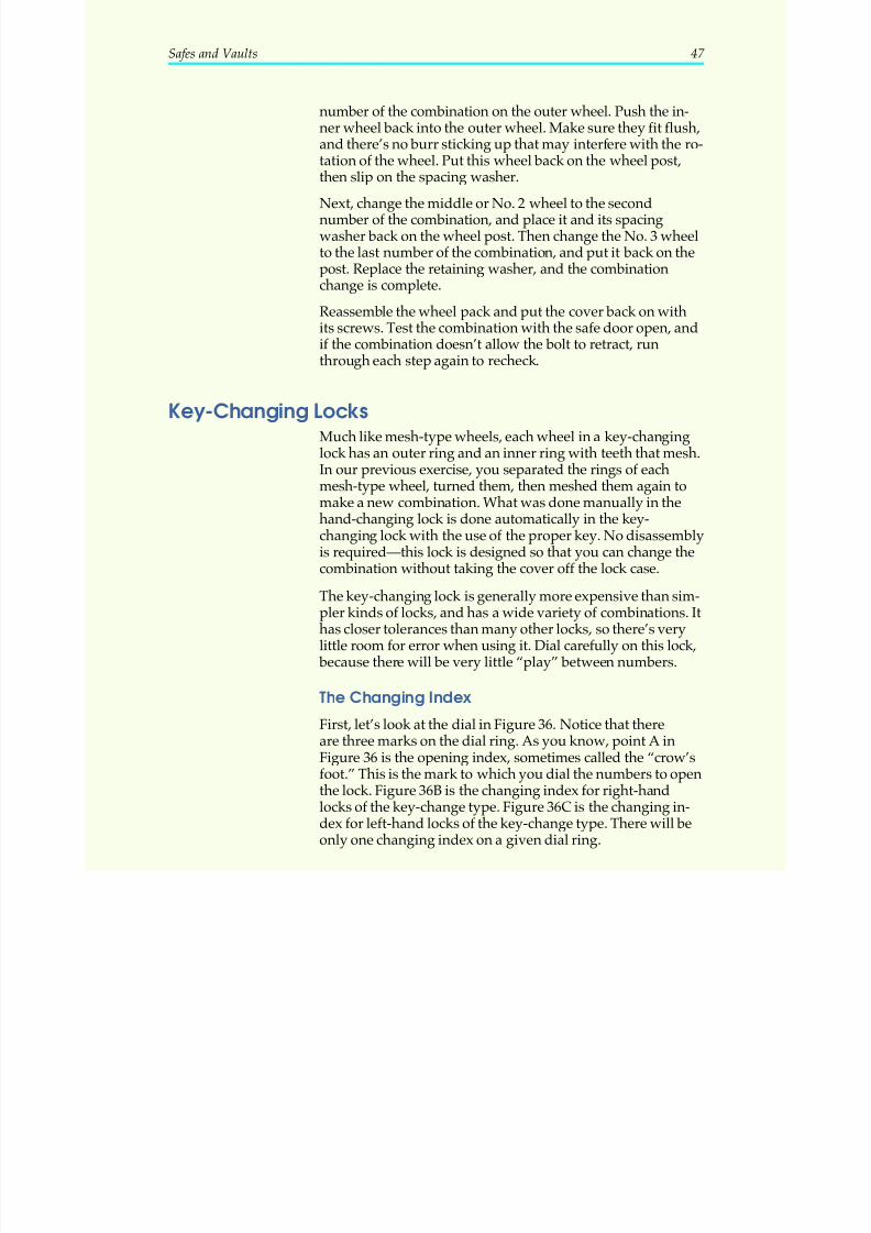
5/12/2018 10 Safes and Vaults - slidepdf.com
http://slidepdf.com/reader/full/10-safes-and-vaults-55a35b88b6c27 51/103
number of the combination on the outer wheel. Push the in-ner wheel back into the outer wheel. Make sure they fit flush,and there’s no burr sticking up that may interfere with the ro-tation of the wheel. Put this wheel back on the wheel post,
then slip on the spacing washer.
Next, change the middle or No. 2 wheel to the secondnumber of the combination, and place it and its spacingwasher back on the wheel post. Then change the No. 3 wheelto the last number of the combination, and put it back on thepost. Replace the retaining washer, and the combinationchange is complete.
Reassemble the wheel pack and put the cover back on withits screws. Test the combination with the safe door open, and
if the combination doesn’t allow the bolt to retract, runthrough each step again to recheck.
Key-Changing LocksMuch like mesh-type wheels, each wheel in a key-changinglock has an outer ring and an inner ring with teeth that mesh.In our previous exercise, you separated the rings of eachmesh-type wheel, turned them, then meshed them again tomake a new combination. What was done manually in the
hand-changing lock is done automatically in the key-changing lock with the use of the proper key. No disassemblyis required—this lock is designed so that you can change thecombination without taking the cover off the lock case.
The key-changing lock is generally more expensive than sim-pler kinds of locks, and has a wide variety of combinations. Ithas closer tolerances than many other locks, so there’s verylittle room for error when using it. Dial carefully on this lock,
because there will be very little “play” between numbers.
The Changing Index
First, let’s look at the dial in Figure 36. Notice that thereare three marks on the dial ring. As you know, point A inFigure 36 is the opening index, sometimes called the “crow’sfoot.” This is the mark to which you dial the numbers to openthe lock. Figure 36B is the changing index for right-handlocks of the key-change type. Figure 36C is the changing in-dex for left-hand locks of the key-change type. There will beonly one changing index on a given dial ring.
Safes and Vaults 47
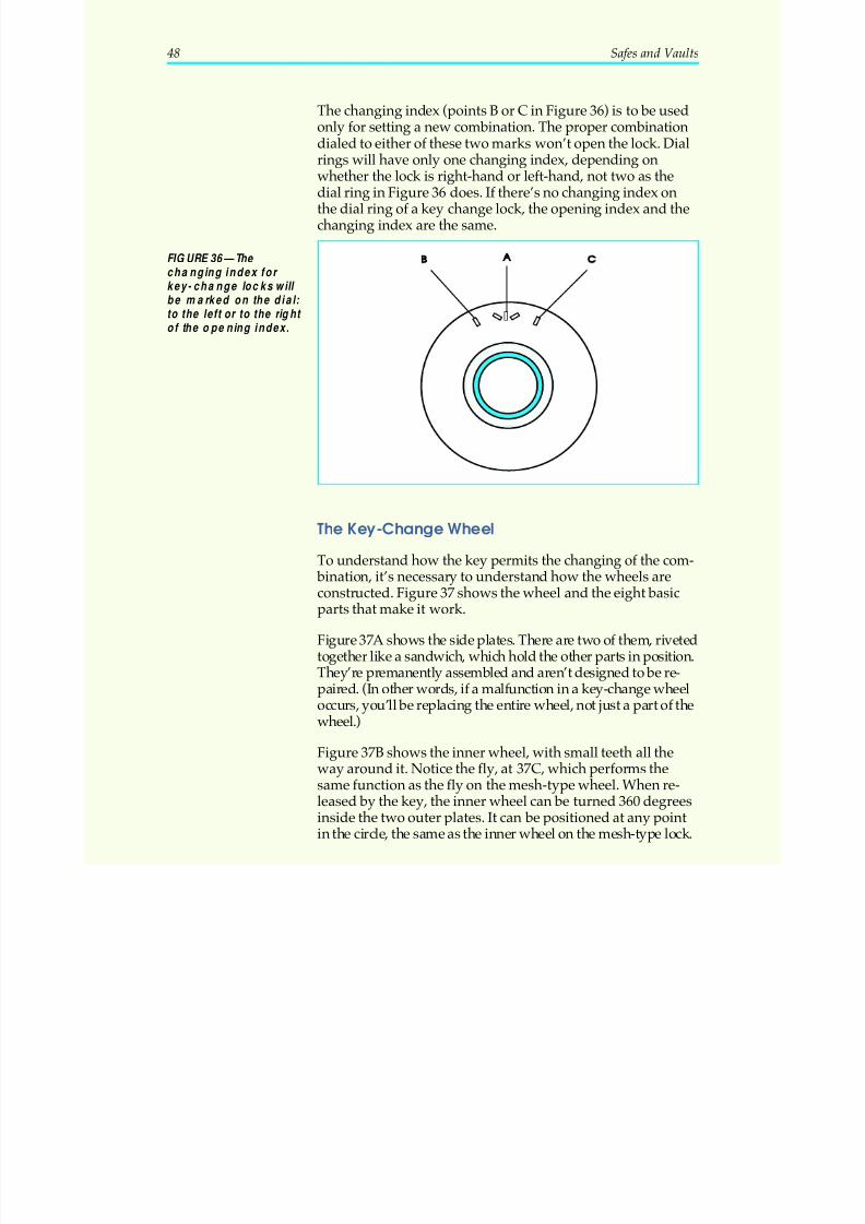
5/12/2018 10 Safes and Vaults - slidepdf.com
http://slidepdf.com/reader/full/10-safes-and-vaults-55a35b88b6c27 52/103
The changing index (points B or C in Figure 36) is to be usedonly for setting a new combination. The proper combinationdialed to either of these two marks won’t open the lock. Dialrings will have only one changing index, depending on
whether the lock is right-hand or left-hand, not two as thedial ring in Figure 36 does. If there’s no changing index onthe dial ring of a key change lock, the opening index and thechanging index are the same.
The Key-Change Wheel
To understand how the key permits the changing of the com- bination, it’s necessary to understand how the wheels areconstructed. Figure 37 shows the wheel and the eight basicparts that make it work.
Figure 37A shows the side plates. There are two of them, rivetedtogether like a sandwich, which hold the other parts in position.They’re premanently assembled and aren’t designed to be re-
paired. (In other words, if a malfunction in a key-change wheeloccurs, you’ll be replacing the entire wheel, not just a part of thewheel.)
Figure 37B shows the inner wheel, with small teeth all theway around it. Notice the fly, at 37C, which performs thesame function as the fly on the mesh-type wheel. When re-leased by the key, the inner wheel can be turned 360 degreesinside the two outer plates. It can be positioned at any pointin the circle, the same as the inner wheel on the mesh-type lock.
48 Safes and Vaults
FIGURE 36—The changing index for key- change locks will be marked on the dial: to the left or to the right of the opening index.
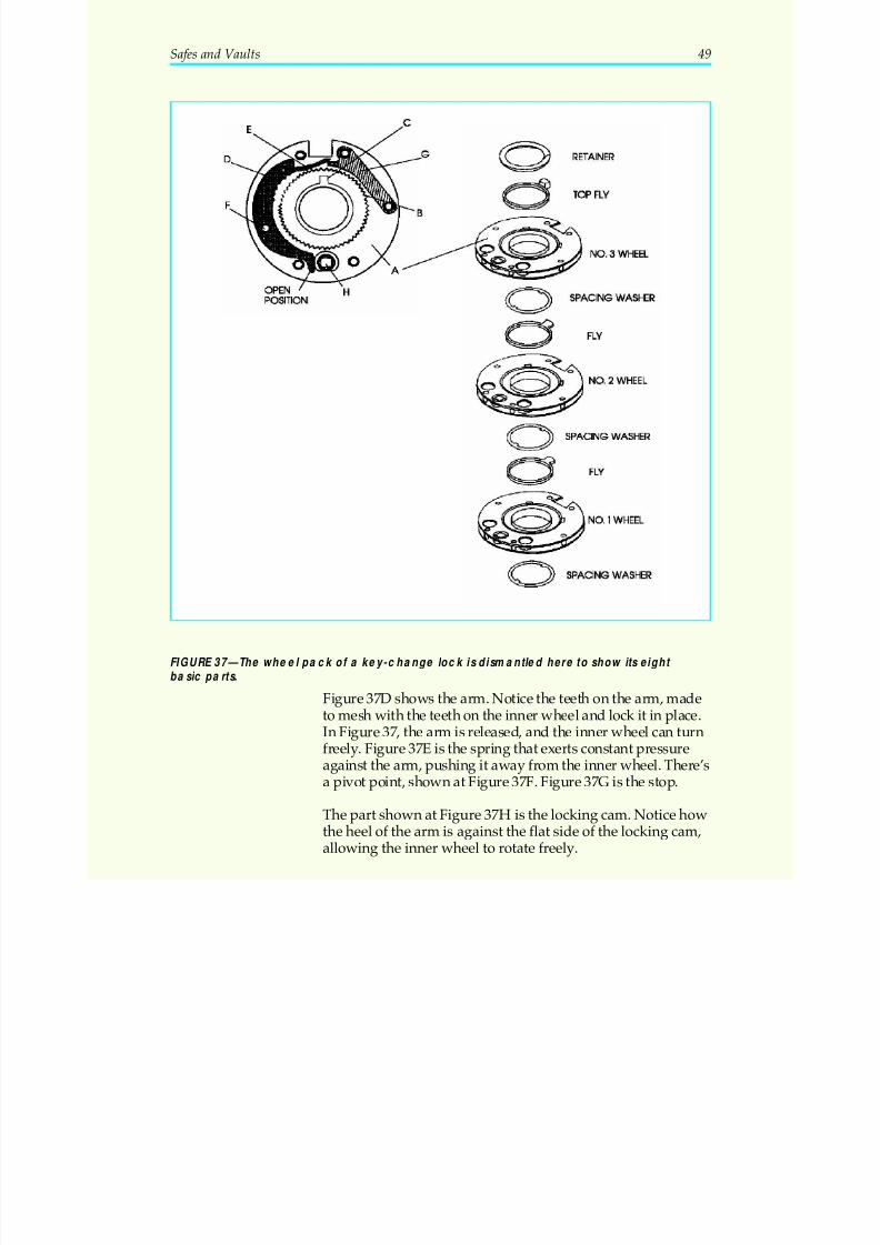
5/12/2018 10 Safes and Vaults - slidepdf.com
http://slidepdf.com/reader/full/10-safes-and-vaults-55a35b88b6c27 53/103
Figure 37D shows the arm. Notice the teeth on the arm, madeto mesh with the teeth on the inner wheel and lock it in place.In Figure 37, the arm is released, and the inner wheel can turnfreely. Figure 37E is the spring that exerts constant pressureagainst the arm, pushing it away from the inner wheel. There’sa pivot point, shown at Figure 37F. Figure 37G is the stop.
The part shown at Figure 37H is the locking cam. Notice howthe heel of the arm is against the flat side of the locking cam,allowing the inner wheel to rotate freely.
Safes and Vaults 49
FIGURE 37—The wheel pack of a key-change lock is dismantled here to show its eight basic parts.
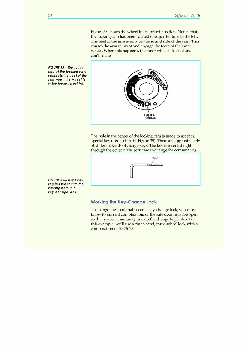
5/12/2018 10 Safes and Vaults - slidepdf.com
http://slidepdf.com/reader/full/10-safes-and-vaults-55a35b88b6c27 54/103
Figure 38 shows the wheel in its locked position. Notice thatthe locking cam has been rotated one quarter turn to the left.The heel of the arm is now on the round side of the cam. Thiscauses the arm to pivot and engage the teeth of the inner
wheel. When this happens, the inner wheel is locked andcan’t rotate.
The hole in the center of the locking cam is made to accept aspecial key used to turn it (Figure 39). There are approximately50 different kinds of charge keys. The key is inserted right
through the cover of the lock case to change the combination.
Working the Key-Change Lock
To change the combination on a key-change lock, you mustknow its current combination, or the safe door must be openso that you can manually line up the change key holes. Forthis example, we’ll use a right-hand, three-wheel lock with acombination of 50-75-25.
50 Safes and Vaults
FIGURE 38—The round side of the locking cam contacts the heel of the arm when the wheel is in the locked position.
FIGURE 39—A special key is used to turn the locking ca m in a key-change lock.
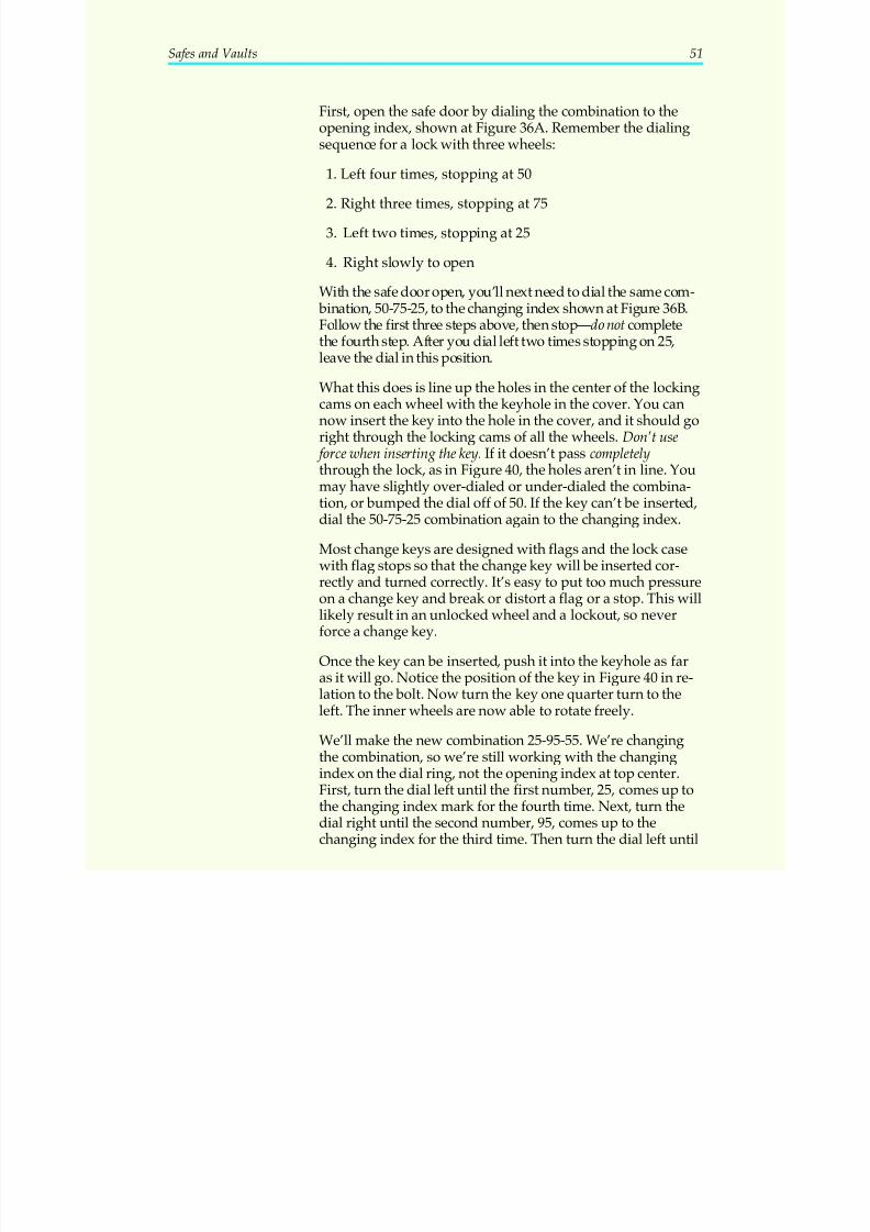
5/12/2018 10 Safes and Vaults - slidepdf.com
http://slidepdf.com/reader/full/10-safes-and-vaults-55a35b88b6c27 55/103
First, open the safe door by dialing the combination to theopening index, shown at Figure 36A. Remember the dialingsequence for a lock with three wheels:
1. Left four times, stopping at 50
2. Right three times, stopping at 75
3. Left two times, stopping at 25
4. Right slowly to open
With the safe door open, you’ll next need to dial the same com- bination, 50-75-25, to the changing index shown at Figure 36B.Follow the first three steps above, then stop—do not complete
the fourth step. After you dial left two times stopping on 25,leave the dial in this position.
What this does is line up the holes in the center of the lockingcams on each wheel with the keyhole in the cover. You cannow insert the key into the hole in the cover, and it should goright through the locking cams of all the wheels. Don’t use
force when inserting the key. If it doesn’t pass completelythrough the lock, as in Figure 40, the holes aren’t in line. Youmay have slightly over-dialed or under-dialed the combina-tion, or bumped the dial off of 50. If the key can’t be inserted,
dial the 50-75-25 combination again to the changing index.
Most change keys are designed with flags and the lock casewith flag stops so that the change key will be inserted cor-rectly and turned correctly. It’s easy to put too much pressureon a change key and break or distort a flag or a stop. This willlikely result in an unlocked wheel and a lockout, so neverforce a change key.
Once the key can be inserted, push it into the keyhole as faras it will go. Notice the position of the key in Figure 40 in re-
lation to the bolt. Now turn the key one quarter turn to theleft. The inner wheels are now able to rotate freely.
We’ll make the new combination 25-95-55. We’re changingthe combination, so we’re still working with the changingindex on the dial ring, not the opening index at top center.First, turn the dial left until the first number, 25, comes up tothe changing index mark for the fourth time. Next, turn thedial right until the second number, 95, comes up to thechanging index for the third time. Then turn the dial left until
Safes and Vaults 51
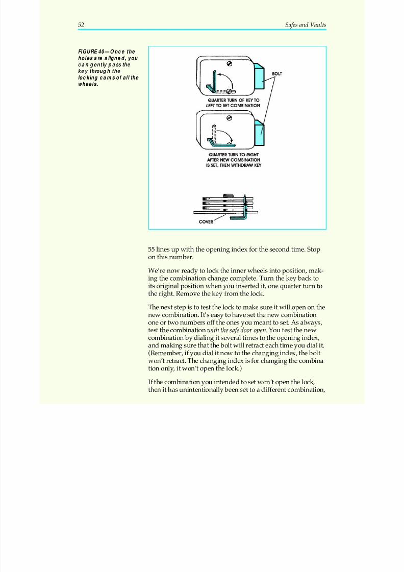
5/12/2018 10 Safes and Vaults - slidepdf.com
http://slidepdf.com/reader/full/10-safes-and-vaults-55a35b88b6c27 56/103
55 lines up with the opening index for the second time. Stopon this number.
We’re now ready to lock the inner wheels into position, mak-ing the combination change complete. Turn the key back toits original position when you inserted it, one quarter turn tothe right. Remove the key from the lock.
The next step is to test the lock to make sure it will open on thenew combination. It’s easy to have set the new combination
one or two numbers off the ones you meant to set. As always,test the combination with the safe door open. You test the newcombination by dialing it several times to the opening index,and making sure that the bolt will retract each time you dial it.(Remember, if you dial it now to the changing index, the boltwon’t retract. The changing index is for changing the combina-tion only, it won’t open the lock.)
If the combination you intended to set won’t open the lock,then it has unintentionally been set to a different combination,
52 Safes and Vaults
FIGURE 40—Once the holes are aligned, you can gently pass the key through the locking cams of all the wheels.
5/12/2018 10 Safes and Vaults - slidepdf.com
http://slidepdf.com/reader/full/10-safes-and-vaults-55a35b88b6c27 57/103
and you’ll have to determine what it now is. You can do this by taking the cover off, turning the dial and watching thegates in the wheels line up under the fence. As each one linesup, take a reading of the dial, and write down the number be-
neath the opening index. This will be the true combination of the lock. You can simply use this combination to open thelock. If you want to try again to set the combination youoriginally intended to set, put the cover back on and repeatthe entire process. Never insert the key when the cover isn’t in
place.
If you take the cover off, you may trigger a relocking devicewithin the lock case. You’ll have to reset it before the lock willwork properly again. To determine what might be lurking
behind the cover of any lock, determine the make and modelof the lock and then consult reference manuals or the manu-facturer’s catalog concerning it.
Another important note: Be sure the key you’re using is theproper key for the lock on which you’re working! All keysaren’t made alike, although they look alike. If the key is tooshort, it won’t disengage all of the inner wheels. To ascertainwhich key is correct, check the lock make and model againsta change key reference manual. The reference manual willgive a tool number. Most change keys have the tool numberengraved on them. (Remember, there are approximately 50different change keys.) Once the key has been turned in thelock, it can’t be withdrawn until it has been turned again.There’s a wing tip on the key which holds it in the lock case,
just as a bit key is held while it’s being turned in a lock.
Safes and Vaults 53
5/12/2018 10 Safes and Vaults - slidepdf.com
http://slidepdf.com/reader/full/10-safes-and-vaults-55a35b88b6c27 58/103
54 Safes and Vaults
Locking It Up! 3
1. What are the three types of hand-changing locks?
_____________________________________________________________________
_____________________________________________________________________
_____________________________________________________________________
2. If you disassemble a lock, then put the wheels back on the wheelpost in different order, will the lock malfunction?
_____________________________________________________________________
_____________________________________________________________________
3. When can you insert the key into a key-changing lock without thecover in place?
_____________________________________________________________________
_____________________________________________________________________
4. What tells you if you have the correct key for a key-changing lock?
_____________________________________________________________________
_____________________________________________________________________
5. Once the combination is changed on a key-change lock, the safe doorshould open when the new combination is dialed to the changing in-dex, correct?
_____________________________________________________________________
_____________________________________________________________________
Check your answers with those on page 91.
5/12/2018 10 Safes and Vaults - slidepdf.com
http://slidepdf.com/reader/full/10-safes-and-vaults-55a35b88b6c27 59/103
SERVICING SAFES
Servicing the Combination LockWhen you’re called to change the combination on a safe lock,always plan to do one other thing as well: service the lock and safe door. To do a good job for a customer and to protectyour professional reputation, it’s a must. There could beworn parts, lack of proper lubrication, screws loose or anynumber of other problems that could cause a lockout. It mayhave nothing to do with the combination you set, or even thelock itself; but if a lockout occurs you may be blamed becauseyou worked on the safe last. While you have the door openand the lock apart, examine the whole mechanism carefullyand suggest to your customer whatever repair work or re-placement parts you feel may be needed. If the customer re-fuses to have the safe serviced, be sure to note on the invoicethat it needed service and state what it needed.
The main concern in servicing the combination lock is tomake sure that the wheels turn without binding or draggingone another out of position. Once a wheel is turned to itsproper position by the dial, it must rest there until the other
wheels are brought into proper position—this is at the heartof how the combination lock works. Wheels that drag eachother out of position are the main cause of lockouts.
When you have all the wheels and spacing washers spreadout in order on a clean surface, spray and wipe each part.Never use oil to lubricate a combination lock. Oil tends to collectdust and become gummy. Use what the manufacturer recom-mends. Sometimes it’s nothing, sometimes it’s a space-agelubricant like “Tri-Flow.” All the lock manufacturers havecustomer service numbers, and they’re happy to assist lock-
smiths. Proper maintenance and lubrication is the best way toprevent lockouts. As you clean them, feel the parts for burrsor rough edges that may catch on other parts and cause drag.Once you’ve made the combination change on mesh-typewheels, make sure the inner and outer wheels fit flush. If theydon’t, the canted part may catch on other parts and causedrag. On screw-type wheels, the screws that act as the drivepins may become rough-edged or loose. When changing thecombination, be sure to move the screws to holes in thewheels that are not worn and will hold them tightly in place.
Safes and Vaults 55
5/12/2018 10 Safes and Vaults - slidepdf.com
http://slidepdf.com/reader/full/10-safes-and-vaults-55a35b88b6c27 60/103
On a key-changing lock, pay special attention to the innerrings of the wheels, because they often come loose. Once youremove the cover from the lock case, but before you take thewheel pack out, try this: insert a screwdriver into the gate of
each wheel, and by applying pressure to the dial in both di-rections you can see if the inner wheel is slipping. If it is,you’ll want to replace that wheel. (You may want to repeatthis test once you’ve changed the combination, to make surethe key has tightened each one properly.) As you remove thewheels, clean and lubricate them. Rough handling oftenshows on the flys, so inspect them. A bright or worn spot ontop of a fly indicates that a drive pin may be riding over it,and this also calls for replacement of the wheel.
When you’ve lubricated all the parts and reassembled themon the wheel post, hold it upright in one hand and with theother hand, work the outer wheel in reverse directions to getall the gates in line. If the wheels do not stay in place—that is,after one is in position, it moves a little while the next one is
being worked—this indicates that a spacing washer is wornand should be replaced.
This is why we’ve been recommending that you test a lock atleast five times with the door open before you close and lock the safe. This probably seemed over-cautious to you at first.
However, if one of the wheels is dragging, it can moveslightly out of position the first time the combination isworked; slightly more out of position the second time it isworked; and increasing more out of position the third, fourth,and fifth time the combination is worked until it causes alockout. If the combination is still working the fifth time youtry it, you can be reasonably sure the wheels are turningfreely, and your customer will be able to get the safe openonce you’re gone.
Before you replace the cover, inspect the spline key, which
connects the drive cam to the spindle. If it is loose or worn,carefully pull it out and replace it. Get a firm grip on the headof the spline with wide grip pliers, as shown in Figure 41,and pull it straight out. Do not use a screwdriver to pry it up,as it’s quite likely to break off at point A in Figure 41.
If the spline head is broken off, the best way to remove it is todrive it out the other side. If necessary, smooth off the brokenedge of the spline with a file so it’s flush with the drive cam. Us-ing a small piece of spring wire slightly smaller than the spline,
56 Safes and Vaults
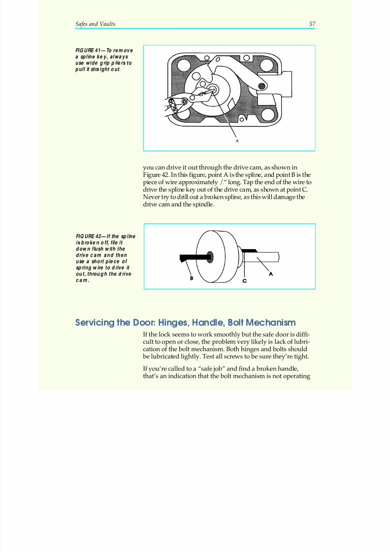
5/12/2018 10 Safes and Vaults - slidepdf.com
http://slidepdf.com/reader/full/10-safes-and-vaults-55a35b88b6c27 61/103
you can drive it out through the drive cam, as shown inFigure 42. In this figure, point A is the spline, and point B is thepiece of wire approximately 3/4“ long. Tap the end of the wire todrive the spline key out of the drive cam, as shown at point C.Never try to drill out a broken spline, as this will damage thedrive cam and the spindle.
Servicing the Door: Hinges, Handle, Bolt MechanismIf the lock seems to work smoothly but the safe door is diffi-cult to open or close, the problem very likely is lack of lubri-cation of the bolt mechanism. Both hinges and bolts should
be lubricated lightly. Test all screws to be sure they’re tight.
If you’re called to a “safe job” and find a broken handle,that’s an indication that the bolt mechanism is not operating
Safes and Vaults 57
FIGURE 41—To remove a spline key, always use wide grip pliers to pull it straight out.
FIGURE 42—If the spline is broken off, file it down flush with the drive cam and then use a short piece of spring wire to drive it out, through the drive cam.
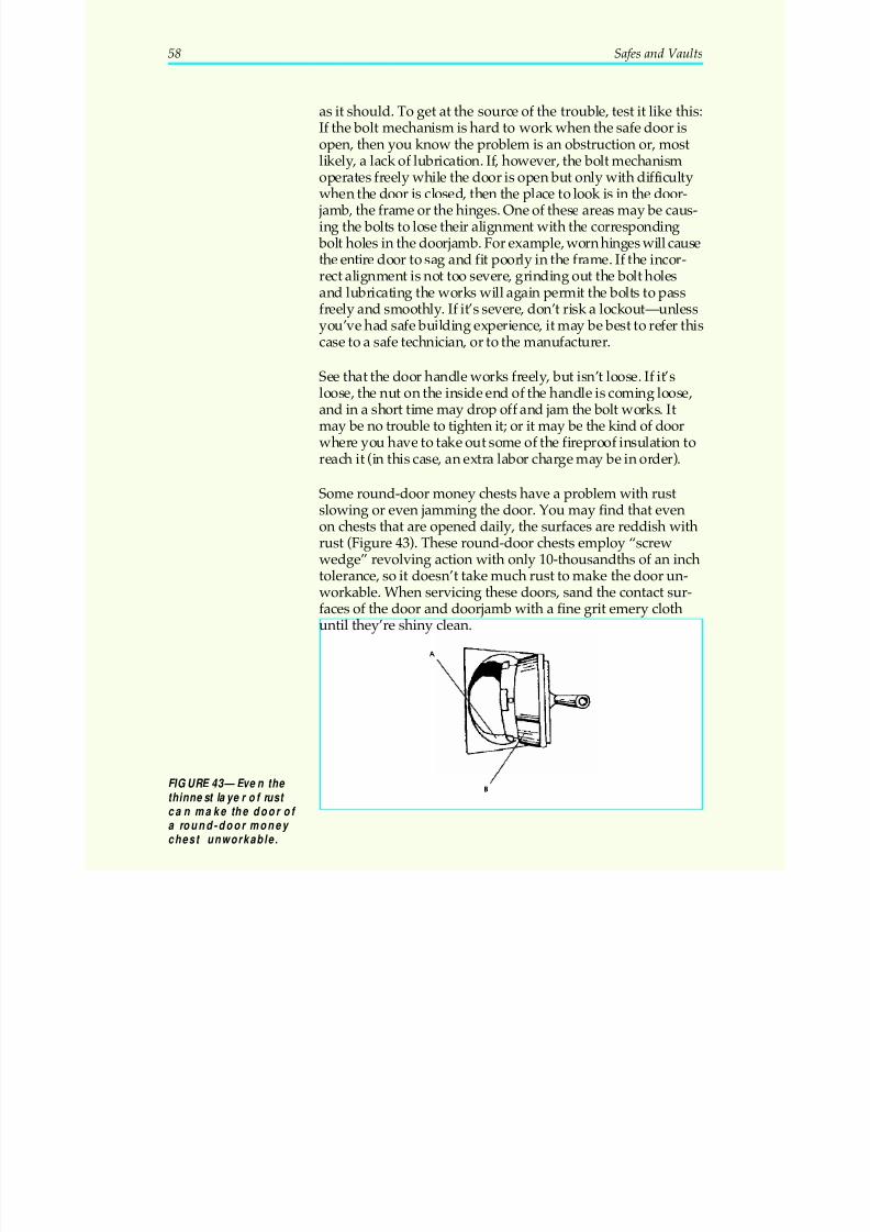
5/12/2018 10 Safes and Vaults - slidepdf.com
http://slidepdf.com/reader/full/10-safes-and-vaults-55a35b88b6c27 62/103
as it should. To get at the source of the trouble, test it like this:If the bolt mechanism is hard to work when the safe door isopen, then you know the problem is an obstruction or, mostlikely, a lack of lubrication. If, however, the bolt mechanism
operates freely while the door is open but only with difficultywhen the door is closed, then the place to look is in the door-
jamb, the frame or the hinges. One of these areas may be caus-ing the bolts to lose their alignment with the corresponding
bolt holes in the doorjamb. For example, worn hinges will causethe entire door to sag and fit poorly in the frame. If the incor-rect alignment is not too severe, grinding out the bolt holesand lubricating the works will again permit the bolts to passfreely and smoothly. If it’s severe, don’t risk a lockout—unlessyou’ve had safe building experience, it may be best to refer this
case to a safe technician, or to the manufacturer.
See that the door handle works freely, but isn’t loose. If it’sloose, the nut on the inside end of the handle is coming loose,and in a short time may drop off and jam the bolt works. Itmay be no trouble to tighten it; or it may be the kind of doorwhere you have to take out some of the fireproof insulation toreach it (in this case, an extra labor charge may be in order).
Some round-door money chests have a problem with rustslowing or even jamming the door. You may find that evenon chests that are opened daily, the surfaces are reddish withrust (Figure 43). These round-door chests employ “screwwedge” revolving action with only 10-thousandths of an inchtolerance, so it doesn’t take much rust to make the door un-workable. When servicing these doors, sand the contact sur-faces of the door and doorjamb with a fine grit emery clothuntil they’re shiny clean.
58 Safes and Vaults
FIGURE 43—Even the thinnest layer of rust ca n make the door of a round-door money chest unworkable.
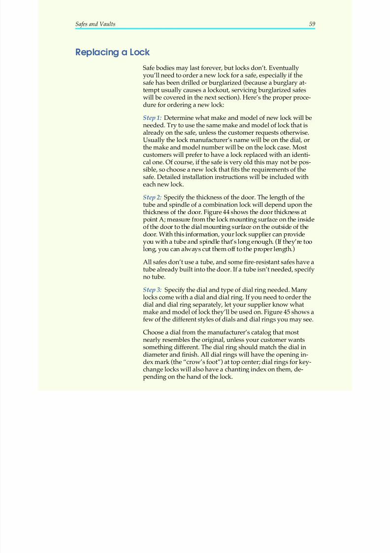
5/12/2018 10 Safes and Vaults - slidepdf.com
http://slidepdf.com/reader/full/10-safes-and-vaults-55a35b88b6c27 63/103
Replacing a Lock
Safe bodies may last forever, but locks don’t. Eventually
you’ll need to order a new lock for a safe, especially if thesafe has been drilled or burglarized (because a burglary at-tempt usually causes a lockout, servicing burglarized safeswill be covered in the next section). Here’s the proper proce-dure for ordering a new lock:
Step 1: Determine what make and model of new lock will beneeded. Try to use the same make and model of lock that isalready on the safe, unless the customer requests otherwise.Usually the lock manufacturer’s name will be on the dial, orthe make and model number will be on the lock case. Most
customers will prefer to have a lock replaced with an identi-cal one. Of course, if the safe is very old this may not be pos-sible, so choose a new lock that fits the requirements of thesafe. Detailed installation instructions will be included witheach new lock.
Step 2: Specify the thickness of the door. The length of thetube and spindle of a combination lock will depend upon thethickness of the door. Figure 44 shows the door thickness atpoint A; measure from the lock mounting surface on the insideof the door to the dial mounting surface on the outside of the
door. With this information, your lock supplier can provideyou with a tube and spindle that’s long enough. (If they’re toolong, you can always cut them off to the proper length.)
All safes don’t use a tube, and some fire-resistant safes have atube already built into the door. If a tube isn’t needed, specifyno tube.
Step 3: Specify the dial and type of dial ring needed. Manylocks come with a dial and dial ring. If you need to order thedial and dial ring separately, let your supplier know what
make and model of lock they’ll be used on. Figure 45 shows afew of the different styles of dials and dial rings you may see.
Choose a dial from the manufacturer’s catalog that mostnearly resembles the original, unless your customer wantssomething different. The dial ring should match the dial indiameter and finish. All dial rings will have the opening in-dex mark (the “crow’s foot”) at top center; dial rings for key-change locks will also have a chanting index on them, de-pending on the hand of the lock.
Safes and Vaults 59
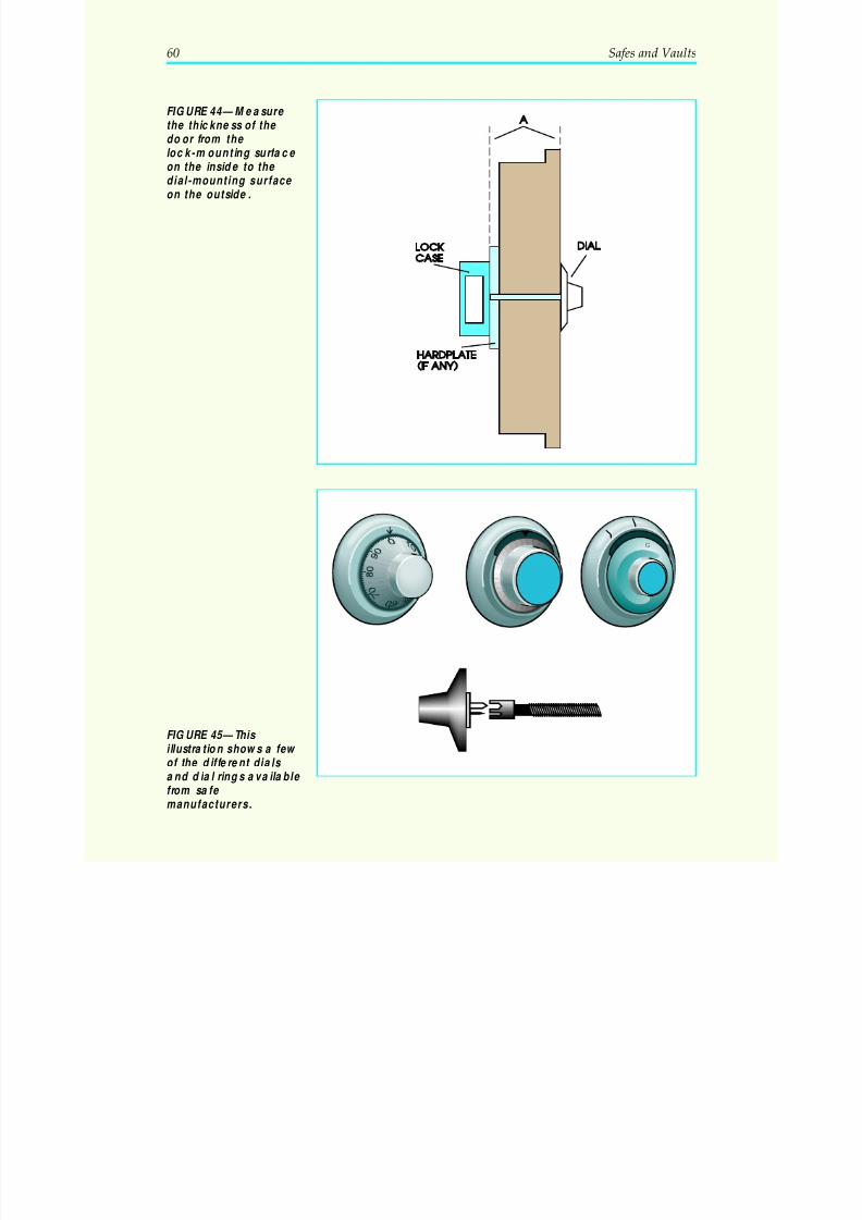
5/12/2018 10 Safes and Vaults - slidepdf.com
http://slidepdf.com/reader/full/10-safes-and-vaults-55a35b88b6c27 64/103
60 Safes and Vaults
FIGURE 44—Measure the thickness of the door from the lock-mounting surface
on the inside to the dial-mounting surface on the outside.
9 G
FIGURE 45—This illustration shows a few of the different dials and dial rings available from safe manufacturers.
5/12/2018 10 Safes and Vaults - slidepdf.com
http://slidepdf.com/reader/full/10-safes-and-vaults-55a35b88b6c27 65/103
Step 4: Once all the correct materials are received, removethe old lock and install the new lock according to the instruc-tions that come with it. Always remember your presentationto the customer: be professional, organized, and neat as you
work. Clean up your work area when you’re finished install-ing the lock. Don’t shut the safe door yet.
Step 5: Test the lock; then change the combination. Lockscoming from the same factory are often set to the same com-
bination. The instructions with each lock will give you these“factory numbers.” Make sure the new lock is functioningproperly by dialing it to these numbers and retracting the
bolt, while the safe door is open. If it’s working properly, changethe combination as you learned in the last section. Then test the
new combination at least five times with the door open to makesure the new combination works smoothly. While the door isstill open, ask your customer to work the new combination. Thatway the customer is personally assured that the lock is working,and that you’ve done the job you were called to do.
Step 6: Let your customer replace valuables in the safe, shutand lock the door. Do this step only after Steps 1 through 5are completed! You or your customer will want to work thecombination once more, just to show your customer that thedoor will open.
Servicing a Burglarized Safe
While the average locksmith performs only basic services onsafes, it’s perfectly possible that a customer may call you toask for guidance or advice, especially if a safe has been bur-glarized. The customer may have no idea of how to go aboutgetting the safe repaired or replaced.
If you get a call on a safe that’s been burglarized, the firstthing to ask the customer is: have the police finished their in-vestigation of it? Never touch a safe in such a situation untilthe police give their OK.
Burglars can leave a safe in a very dangerous condition. Theyusually cause a lockout, but before you attempt to open thesafe or make repairs, make sure you and anyone else nearbywon’t be injured.
Safes and Vaults 61
5/12/2018 10 Safes and Vaults - slidepdf.com
http://slidepdf.com/reader/full/10-safes-and-vaults-55a35b88b6c27 66/103
Explosives are rarely used today. Even so, always look forsigns of an unexploded charge of nitroglycerin or other liquidwhich might be inside the safe. The presence of soap or somekind of waterproof putty around the door indicates the pres-
ence of a liquid explosive like nitro (soap acts as a sealant tokeep the explosive in place). If you suspect the safe has beenprepared for blowing, use every precaution! Alert theauthorities and the owner, and keep people out of the areauntil the explosive is neutralized.
Another dangerous condition is severed hinge pins. Alwaysexamine the hinge pins on a burglarized safe, even if the hingecaps are still in place. The pins may be sawed in two rightwhere the two halves of the hinges come together—leaving the
door hanging precariously, although it doesn’t look it. Safedoors are very heavy, especially on the larger safes. Makesure the door cannot fall on you or anyone else, injuringhands or feet, before you begin to work on it.
Burglars seem to love to knock off the dials and handles of safes, as if this will make them easier to open! Occasionallyyou will find a dial knocked off but the spindle still free andmovable. If so, you might try attaching a dial and dial ring tothe spindle, and working the combination the owner givesyou. Since it’s probable that you won’t attach the two parts
perfectly, work the dial from two to five numbers over or un-der the correct combination numbers. If this doesn’t work,drilling the lock is probably the only answer.
Your goal is to get the safe open with as little further damageto it as possible. If your first drill hole misses its mark, fan an-other hole up or down, left or right, from the same drill hole inthe door, instead of making a second drill hole beside the first.
Once the lock is open, the next step is to retract the bolt. But if
the handle controlling the bolt works was also knocked off, itwon’t be easy. If the safe is small, you may be able to turn itover on its side once the lock is open, and vibrate the doorwith a mallet or hammer to get the bolts to drop back bygravity. If this is impractical, you’ll have to drill for the boltmechanism. Again, it helps greatly to know the make andmodel of the safe you’re working on, so that you can deter-mine the kind of bolt mechanism in it and where it is withinthe safe door. In most safes, if you drill a hole directly abovethe hole of the handle, you’ll contact some part of the bolt
62 Safes and Vaults
5/12/2018 10 Safes and Vaults - slidepdf.com
http://slidepdf.com/reader/full/10-safes-and-vaults-55a35b88b6c27 67/103
mechanism. If you can work it with a punch, wire, or othertool, you may be able to retract the bolt.
If after all this the door still won’t open, then the burglary (or
your repair attempts) probably set off a relocking device andyes, you’ll have to drill for that too. At this point, it’s impor-tant to know the make and model of the safe you’re workingon and the make and model of the lock that’s on it, in orderto determine where the relockers are. Without this informa-tion, you may pepper the outside of the safe with drill holesand still not get it open! If this information isn’t readily avail-able, it may be better to refer the case to a safe technician.
Once the safe is open, you’ll need to test all working partsand, with the owner’s OK, replace broken, bent or damaged
parts. In almost all cases you’ll need to order a new lock andinstall it, as explained in the last section.
Safes and Vaults 63
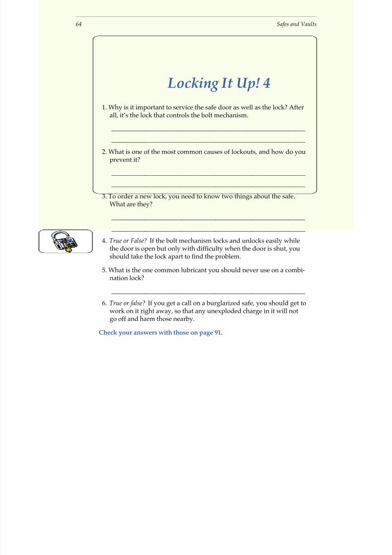
5/12/2018 10 Safes and Vaults - slidepdf.com
http://slidepdf.com/reader/full/10-safes-and-vaults-55a35b88b6c27 68/103
64 Safes and Vaults
Locking It Up! 4
1. Why is it important to service the safe door as well as the lock? Afterall, it’s the lock that controls the bolt mechanism.
_____________________________________________________________________
_____________________________________________________________________
2. What is one of the most common causes of lockouts, and how do youprevent it?
_____________________________________________________________________
_____________________________________________________________________
3. To order a new lock, you need to know two things about the safe.What are they?
_____________________________________________________________________
_____________________________________________________________________
4. True or False? If the bolt mechanism locks and unlocks easily whilethe door is open but only with difficulty when the door is shut, youshould take the lock apart to find the problem.
5. What is the one common lubricant you should never use on a combi-nation lock?
_____________________________________________________________________
6. True or false? If you get a call on a burglarized safe, you should get to
work on it right away, so that any unexploded charge in it will notgo off and harm those nearby.
Check your answers with those on page 91.
5/12/2018 10 Safes and Vaults - slidepdf.com
http://slidepdf.com/reader/full/10-safes-and-vaults-55a35b88b6c27 69/103
SAFELOCKOUTS
What a Locksmith Should Know
Safe opening has a long and colorful past. Gangster moviesespecially romanticized the “safecracker.” He was usually ashady little character who could put his ear to the door and,with a well-trained sense of touch, turn the dial and spring itopen like magic.
Actually, magic doesn’t get a locked safe open—trainingdoes. This study unit isn’t designed to provide the highly
detailed training it would take to make you an expert safe-cracker. You’re ready, however, to apply the skills you’velearned in previous sections to the challenging work of get-ting a locked safe open. In this section of the text, we’ll discussthe following topics:
• What questions to ask the customer to help you diag-nose the cause of the lockout
• Troubleshooting techniques that save time and expensefor you and your customer
• The most common causes of lockouts, and how to han-dle them
• How to determine if a lockout is likely to be permanentor merely temporary, and what your next step should be
• How locked safes are opened: the basic techniquesexplained
Now, let’s start our discussion with the theory of safemanipulation.
Theory of Safe Manipulation
Manipulation is the process of opening a locked safe withoutknowing the combination of the lock and without the use of force or explosives. The safecracker in the gangster movies,
by turning the dial slowly and listening to the parts movinginside the door, was using manipulation to get the safe open.
Safes and Vaults 65
5/12/2018 10 Safes and Vaults - slidepdf.com
http://slidepdf.com/reader/full/10-safes-and-vaults-55a35b88b6c27 70/103
If you’ve been working hands-on with combination locks,you probably have a sense of how manipulation works. Asyou turn the dial slowly, you can feel rough and smoothspots. Have you noticed the friction increasing slightly as
each wheel is picked up by the drive cam? You might hearthe click of the drive pins as they strike one another, settingthe wheels in motion, or the click of the fence dropping intothe gates. These sensations wouldn’t have made sense to you
before, but your training in previous sections now tells youwhat’s happening inside the lock. In theory, these sensationscould be translated into numbers that might open the safe.
Manipulation was more practical in “Bugsy’s” time than to-day, however. Because lock parts were machined with lessprecision years ago, there was more error in all the parts,which made them easier to hear, feel and manipulate. To-day’s locks, however, are made with very close tolerances onprecision machinery. It’s much more difficult to try to deter-mine the combination by the sound or feel of the wheelsturning in the lock.
Manipulation is a controversial topic in the locksmithingindustry. Most highly skilled safe technicians will attemptmanipulation first on most lockouts, depending on the typeof safe, type of lock, and type of lockout.
Modern safecrackers have gone to faster methods of opening,such as drilling. Safes can be drilled and repaired quickly,with little evidence of damage. Drilling isn’t necessary inevery case, however. The next section will describe how tofigure out what kind of lockout you’re faced with, and thiswill tell you how best to approach it.
All Lockouts Are Not AlikeLockouts can be permanent or temporary. Temporary lockouts
usually don’t require drilling, but permanent lockouts usually do.
You learned earlier that one of the first questions to ask whenyou get a “safe call” is: Is the combination known? A lockoutis more likely to be permanent if the combination is known
because the problem is probably due to mechanical failure. Asecond key question is: Has the safe locked up suddenly, orhas it been difficult to open for some time? If the safe has
been difficult to open for some time, it’s probably a tempo-rary lockout.
66 Safes and Vaults
5/12/2018 10 Safes and Vaults - slidepdf.com
http://slidepdf.com/reader/full/10-safes-and-vaults-55a35b88b6c27 71/103
If the safe has locked up suddenly, it has probably suffered a breakdown of one of the mechanical functions and will have to be drilled. You can generally tell by the feel of the dial if anyparts are not functioning properly. The dial may be extremely
hard to turn; or it may spin too freely and easily. Both conditionsindicate that it has lost control of the wheels, which means youhave little chance of working the lock without drilling it.
Troubleshooting
First, talk to the owner of the safe and learn as much as youcan about the safe and its use. If the safe is used frequently,there’s a chance the problem is caused by excessive wear.
This is usually a temporary lockout.Temporary lockouts are often caused by dirt in the lock, orworn parts. Where the lock may be gummed up by dirt, trydialing the numbers slowly, stopping on each number, andtapping the face of the door just above the dial with a dead-
blow hammer. (A dead-blow hammer is a hammer with ashot-filled head; it won’t mar the surface you’re working onand won’t rebound.) The vibration can help a sticking partfall into the correct position.
Lockouts quite often are caused by one wheel dragging anotherout of position. Sometimes the drag will move the wheel only anumber or two to the left or right. This may be just enough tokeep the gates from lining up properly, so the fence won’t dropin and allow the lock to open. Try dialing the combination oneor two numbers to either side of the known combination. For ex-ample, if the combination is 36-7-50, try 35-6-49, 34-5-48, 37-8-51,or 38-9-52. Rapping on the face of the safe door as each numberis dialed will often help in this case too.
If your customer is exasperated (and they usually are), don’t
discount the possibility that they’ve got the combination, orthe direction of turns, or the number of turns between num- bers wrong. The combination they give you may be the rightnumbers, but in reverse order; also, they may be too upset toturn the dial the right number of times, or as carefully as theyshould. After dialing the combination carefully, turn the dialslowly to its open position, and rap on the door with the woodenmallet. Your customer may be turning the dial so quickly thatthe nose of the lever doesn’t fully engage the gate in the drivecam, allowing the bolt to be retracted.
Safes and Vaults 67
5/12/2018 10 Safes and Vaults - slidepdf.com
http://slidepdf.com/reader/full/10-safes-and-vaults-55a35b88b6c27 72/103
If the safe is used infrequently, the owner may simply haveforgotten the combination. By questioning the owner about
birthdate, age, car license plate number, address, date safewas purchased or serviced, etc., you or the customer may
come up with the right numbers. Even though these aren’tgood numbers to use, many people still use them, especiallyon safes in their homes. Also be aware that one numbermight suggest the next number; combinations like 20-40-60,or multiples of 5, are not uncommon.
The owner may also have gotten the order of the numbersmixed up or reversed. They may insist they’re right, and youshould always be diplomatic, but try the numbers on the lock in different order, or in reverse order.
Always inspect the area around the safe. By some quirk of human nature, you’ll very often find the combination writ-ten, usually in reverse order, on walls or furniture withinarm’s length. Doorjambs and window sills seem to be univer-sal favorite places to record combination numbers. You mightfind the combination written on the safe itself, in some incon-spicuous spot.
Another common cause of a safe failing to open is turning thedial in the wrong direction. Try the combination is both di-rections, and be sure you make the proper number of turns
between each number. The customer will often get thiswrong if the safe is not used frequently. Many people, with athree-digit combination like 50-50-50, will start out by dialingthe number three times to the opening index, instead of cor-rectly dialing it four times.
DrillingIf all of the above fails to open the safe, the lockout is proba-
bly permanent and drilling is called for. Drilling is a fast andfairly accurate way to get a safe open, but should be handledwith care. One of the marks of a professional is knowingwhen to turn a job over to the person most qualified to do it.Safe technicians specialize in drilling safes.
How Drilling Works
Remember the function of the hole in the cover of hole-typelocks? It allowed you to see into the back of the lock case and
68 Safes and Vaults
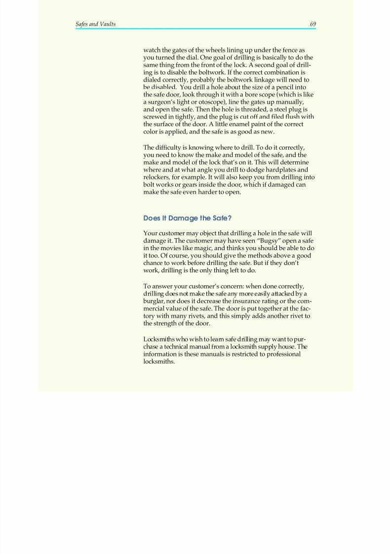
5/12/2018 10 Safes and Vaults - slidepdf.com
http://slidepdf.com/reader/full/10-safes-and-vaults-55a35b88b6c27 73/103
watch the gates of the wheels lining up under the fence asyou turned the dial. One goal of drilling is basically to do thesame thing from the front of the lock. A second goal of drill-ing is to disable the boltwork. If the correct combination is
dialed correctly, probably the boltwork linkage will need to be disabled. You drill a hole about the size of a pencil intothe safe door, look through it with a bore scope (which is likea surgeon’s light or otoscope), line the gates up manually,and open the safe. Then the hole is threaded, a steel plug isscrewed in tightly, and the plug is cut off and filed flush withthe surface of the door. A little enamel paint of the correctcolor is applied, and the safe is as good as new.
The difficulty is knowing where to drill. To do it correctly,
you need to know the make and model of the safe, and themake and model of the lock that’s on it. This will determinewhere and at what angle you drill to dodge hardplates andrelockers, for example. It will also keep you from drilling into
bolt works or gears inside the door, which if damaged canmake the safe even harder to open.
DoesIt Damage the Safe?
Your customer may object that drilling a hole in the safe willdamage it. The customer may have seen “Bugsy” open a safein the movies like magic, and thinks you should be able to doit too. Of course, you should give the methods above a goodchance to work before drilling the safe. But if they don’twork, drilling is the only thing left to do.
To answer your customer’s concern: when done correctly,drilling does not make the safe any more easily attacked by a
burglar, nor does it decrease the insurance rating or the com-mercial value of the safe. The door is put together at the fac-tory with many rivets, and this simply adds another rivet tothe strength of the door.
Locksmiths who wish to learn safe drilling may want to pur-chase a technical manual from a locksmith supply house. Theinformation is these manuals is restricted to professionallocksmiths.
Safes and Vaults 69
5/12/2018 10 Safes and Vaults - slidepdf.com
http://slidepdf.com/reader/full/10-safes-and-vaults-55a35b88b6c27 74/103
70 Safes and Vaults
Locking It Up! 5
1. What is the “manipulation” method?
_____________________________________________________________________
_____________________________________________________________________
2. True or False? If the dial spins freely like a top, you probably won’tneed to drill the safe.
3. Dialing the combination ___________, and _____________ on thedoor, will sometimes vibrate sticking parts into place and allow thesafe door to be opened.
4. When confronted by an angry or upset safe owner, it’s very impor-tant for the locksmith to be ____________.
Check your answers with those on page 92.
5/12/2018 10 Safes and Vaults - slidepdf.com
http://slidepdf.com/reader/full/10-safes-and-vaults-55a35b88b6c27 75/103
SAFEDEPOSITBOXES
What Is a Safe Deposit Box?
Safe deposit boxes are like small personal safes within a bank. They offer maximum security against theft and fire foralmost anything the renter wants to put in them—not onlycash but valuables like jewelry, wills, and other importantpapers. The renter has complete privacy and ready access tothe cash and other items. At the same time, the renter has allthe security that a bank offers.
To gain entry to the safe deposit box, both the renter and a bank employee must be present, with their keys. Each safedeposit box is operated by a dual-custody lock —a lock whichcan be opened only by the use of two different keys.
The bank’s key is called the guard key. It opens only part of the lock. The other key is the renter’s key. The renter can’topen the safe deposit box without a bank employee presentwith the guard key, and the bank employee cannot open the
box without the renter present with the renter’s key.
What does this mean to a locksmith? Steady, well-paying re-
peat business! These locks need to be serviced just as otherlocks do. Much like the door locks of hotels and apartmenthouses, the renter’s lock also needs to be changed each timethere’s a new renter. Renters often misplace their keys andneed to have a duplicate made. This chapter will give you theinformation you need to make these dual-custody locks aprofitable part of your business.
Who Can Open a Safe Deposit Box?
The contents of a safe deposit box are not available to anyone,other than the renter, without a court order. The question of who can open a safe deposit box involves many legal details,
but usually locksmiths don’t get involved in these questions.All the locksmith really needs is the bank’s authorization toservice or open a safe deposit box.
Security in the safe deposit box section of a bank is very strict.Usually each person entering the safe deposit box section is
Safes and Vaults 71
5/12/2018 10 Safes and Vaults - slidepdf.com
http://slidepdf.com/reader/full/10-safes-and-vaults-55a35b88b6c27 76/103
required to show identification and sign a register. There’sone thing you should insist on with the bank: have a bank employee present whenever you’re working on a safe deposit
box. Don’t be alone in the safe deposit section of a bank! In
most banks this is standard procedure, but in small townswhere the banker and the locksmith know each other well,they may become lax about this rule. Having a witnessguards your professional reputation.
Because banks are responsible for the contents of their safedeposit boxes, they want control over the duplication of keys.Renters are given two keys. If one of them is lost, the renter issupposed to contact the bank, and the bank will send therenter to the locksmith to get a duplicate made. Again, aslong as you have authorization from the bank to make theduplicate, you’ll be safe in doing so.
Where Does the Locksmith Fit In?
Banks usually call upon a locksmith to do two things withtheir safe deposit boxes: make and/or duplicate renters’ keys;and open a locked box if the renter’s key is lost. Some banksalso ask locksmiths to change the locks on the boxes regu-larly, to ensure the security of the boxes.
We’ll begin by taking a close look at the typical dual-custodylever lock found on most safe deposit boxes.
The Dual-Custody Lever Lock
Lever locks are made by several different companies, includ-ing Bates, Diebold, Eagle, Herring-Hall-Marvin, Miller,Mosler, Victor, Western, Yale, York, Remington-Sermen, and
Sargent & Greenleaf. Some of these manufacturers makemore than one style of lock and door, but they’re all verysimilar in design.
A dual-custody lever lock (Figure 46) actually contains two locks.Two keys are required to operate the lock; this adds extra secu-rity to the container. The case (46A) is usually made of bronze orsome similar metal, although older cases are made of steel. Thekeyway shown at point B is for the guard key, the key whichis retained by the bank. This same guard key may fit all of the
72 Safes and Vaults
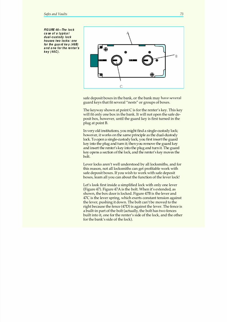
5/12/2018 10 Safes and Vaults - slidepdf.com
http://slidepdf.com/reader/full/10-safes-and-vaults-55a35b88b6c27 77/103
safe deposit boxes in the bank, or the bank may have severalguard keys that fit several “nests” or groups of boxes.
The keyway shown at point C is for the renter’s key. This keywill fit only one box in the bank. It will not open the safe de-posit box, however, until the guard key is first turned in theplug at point B.
In very old institutions, you might find a single-custody lock;
however, it works on the same principle as the dual-dustodylock. To open a single-custody lock, you first insert the guardkey into the plug and turn it; then you remove the guard keyand insert the renter’s key into the plug and turn it. The guardkey opens a section of the lock, and the renter’s key moves the
bolt.
Lever locks aren’t well understood by all locksmiths, and forthis reason, not all locksmiths can get profitable work withsafe deposit boxes. If you wish to work with safe deposit
boxes, learn all you can about the function of the lever lock!
Let’s look first inside a simplified lock with only one lever(Figure 47). Figure 47A is the bolt. When it’s extended, asshown, the box door is locked. Figure 47B is the lever and47C is the lever spring, which exerts constant tension againstthe lever, pushing it down. The bolt can’t be moved to theright because the fence (47D) is against the lever. The fence isa built-in part of the bolt (actually, the bolt has two fences
built into it, one for the renter’s side of the lock, and the otherfor the bank’s side of the lock).
Safes and Vaults 73
A
B
C
FIGURE 46—The lock case of a typical dual-custody lock houses two locks: one
for the guard key (46B) and one for the renter’s key (46C).
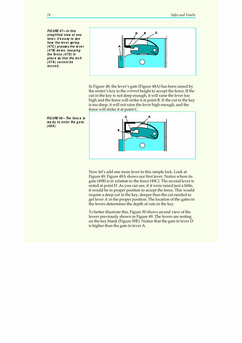
5/12/2018 10 Safes and Vaults - slidepdf.com
http://slidepdf.com/reader/full/10-safes-and-vaults-55a35b88b6c27 78/103
In Figure 48, the lever’s gate (Figure 48A) has been raised bythe renter’s key to the correct height to accept the fence. If the
cut in the key is not deep enough, it will raise the lever toohigh and the fence will strike it at point B. If the cut in the keyis too deep, it will not raise the lever high enough, and thefence will strike it at point C.
Now let’s add one more lever to this simple lock. Look atFigure 49. Figure 49A shows our first lever. Notice where itsgate (49B) is in relation to the fence (49C). The second lever isnoted at point D. As you can see, if it were raised just a little,it would be in proper position to accept the fence. This would
require a deep cut in the key, deeper than the cut needed toget lever A in the proper position. The location of the gates inthe levers determines the depth of cuts in the key.
To better illustrate this, Figure 50 shows an end view of thelevers previously shown in Figure 49. The levers are restingon the key blank (Figure 50E). Notice that the gate in lever Dis higher than the gate in lever A.
74 Safes and Vaults
FIGURE 47—In this simplified view of one lever, it’s easy to see how the lever spring (47C) presses the lever (47B) down, keeping the fence (47D) in place so that the bolt (47A) ca nnot be moved.
FIGURE 48—The fence is rea dy to enter the gate (48A).
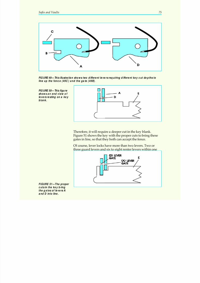
5/12/2018 10 Safes and Vaults - slidepdf.com
http://slidepdf.com/reader/full/10-safes-and-vaults-55a35b88b6c27 79/103
Therefore, it will require a deeper cut in the key blank.Figure 51 shows the key with the proper cuts to bring thesegates in line, so that they both can accept the fence.
Of course, lever locks have more than two levers. Two orthree guard levers and six to eight renter levers within one
Safes and Vaults 75
FIGURE 49—This illustration shows two different levers requiring different key cut depths to
line up the fence (49C) and the gate (49B).
FIGURE 50—This figure shows an end view of levers resting on a key blank.
FIGURE 51—The proper cuts in the key bring the gates of levers Aand D into line.
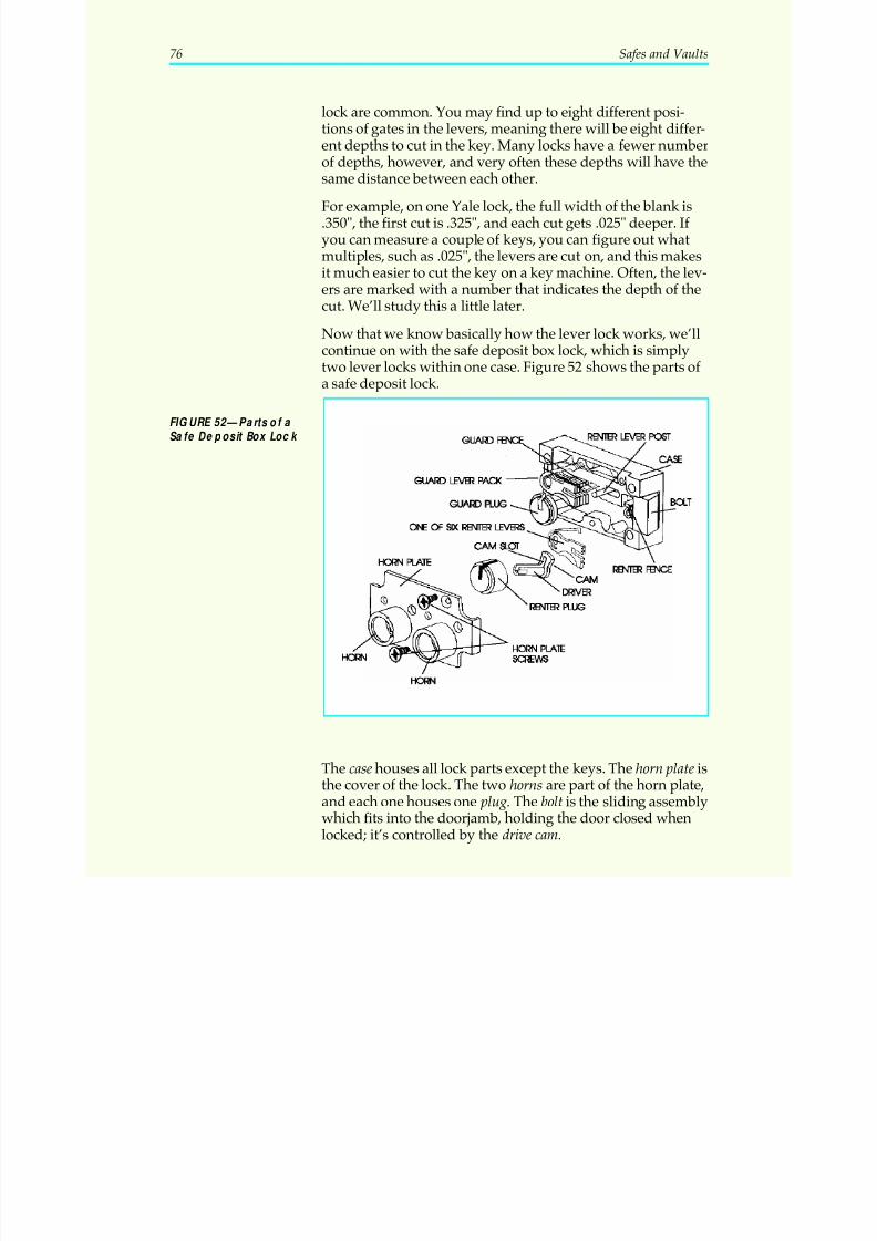
5/12/2018 10 Safes and Vaults - slidepdf.com
http://slidepdf.com/reader/full/10-safes-and-vaults-55a35b88b6c27 80/103
lock are common. You may find up to eight different posi-tions of gates in the levers, meaning there will be eight differ-ent depths to cut in the key. Many locks have a fewer numberof depths, however, and very often these depths will have the
same distance between each other.
For example, on one Yale lock, the full width of the blank is.350", the first cut is .325", and each cut gets .025" deeper. If you can measure a couple of keys, you can figure out whatmultiples, such as .025", the levers are cut on, and this makesit much easier to cut the key on a key machine. Often, the lev-ers are marked with a number that indicates the depth of thecut. We’ll study this a little later.
Now that we know basically how the lever lock works, we’ll
continue on with the safe deposit box lock, which is simplytwo lever locks within one case. Figure 52 shows the parts of a safe deposit lock.
The case houses all lock parts except the keys. The horn plate isthe cover of the lock. The two horns are part of the horn plate,and each one houses one plug. The bolt is the sliding assemblywhich fits into the doorjamb, holding the door closed whenlocked; it’s controlled by the drive cam.
76 Safes and Vaults
FIGURE 52—Parts of a Safe Deposit Box Lock
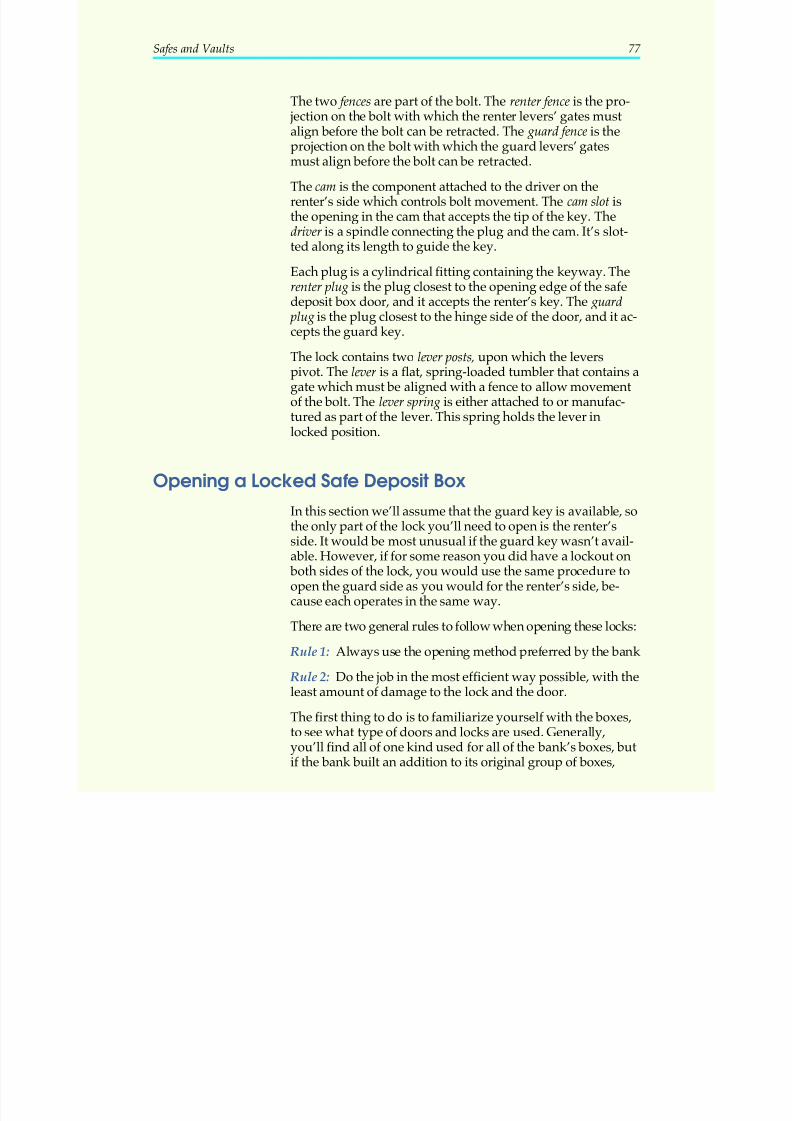
5/12/2018 10 Safes and Vaults - slidepdf.com
http://slidepdf.com/reader/full/10-safes-and-vaults-55a35b88b6c27 81/103
The two fences are part of the bolt. The renter fence is the pro- jection on the bolt with which the renter levers’ gates mustalign before the bolt can be retracted. The guard fence is theprojection on the bolt with which the guard levers’ gates
must align before the bolt can be retracted.
The cam is the component attached to the driver on therenter’s side which controls bolt movement. The cam slot isthe opening in the cam that accepts the tip of the key. Thedriver is a spindle connecting the plug and the cam. It’s slot-ted along its length to guide the key.
Each plug is a cylindrical fitting containing the keyway. Therenter plug is the plug closest to the opening edge of the safedeposit box door, and it accepts the renter’s key. The guard
plug is the plug closest to the hinge side of the door, and it ac-cepts the guard key.
The lock contains two lever posts, upon which the leverspivot. The lever is a flat, spring-loaded tumbler that contains agate which must be aligned with a fence to allow movementof the bolt. The lever spring is either attached to or manufac-tured as part of the lever. This spring holds the lever inlocked position.
Opening a Locked Safe Deposit Box
In this section we’ll assume that the guard key is available, sothe only part of the lock you’ll need to open is the renter’sside. It would be most unusual if the guard key wasn’t avail-able. However, if for some reason you did have a lockout on
both sides of the lock, you would use the same procedure toopen the guard side as you would for the renter’s side, be-cause each operates in the same way.
There are two general rules to follow when opening these locks: Rule 1: Always use the opening method preferred by the bank
Rule 2: Do the job in the most efficient way possible, with theleast amount of damage to the lock and the door.
The first thing to do is to familiarize yourself with the boxes,to see what type of doors and locks are used. Generally,you’ll find all of one kind used for all of the bank’s boxes, butif the bank built an addition to its original group of boxes,
Safes and Vaults 77
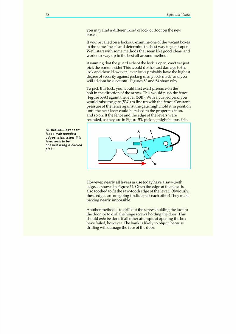
5/12/2018 10 Safes and Vaults - slidepdf.com
http://slidepdf.com/reader/full/10-safes-and-vaults-55a35b88b6c27 82/103
you may find a different kind of lock or door on the new boxes.
If you’re called on a lockout, examine one of the vacant boxes
in the same “nest” and determine the best way to get it open.We’ll start with some methods that seem like good ideas, andwork our way up to the best all-around method.
Assuming that the guard side of the lock is open, can’t we justpick the renter’s side? This would do the least damage to thelock and door. However, lever locks probably have the highestdegree of security against picking of any lock made, and youwill seldom be successful. Figures 53 and 54 show why.
To pick this lock, you would first exert pressure on the
bolt in the direction of the arrow. This would push the fence(Figure 53A) againt the lever (53B). With a curved pick, youwould raise the gate (53C) to line up with the fence. Constantpressure of the fence against the gate might hold it in positionuntil the next lever could be raised to the proper position,and so on. If the fence and the edge of the levers wererounded, as they are in Figure 53, picking might be possible.
However, nearly all levers in use today have a saw-tooth
edge, as shown in Figure 54. Often the edge of the fence isalso toothed to fit the saw-tooth edge of the lever. Obviously,these edges are not going to slide past each other! They makepicking nearly impossible.
Another method is to drill out the screws holding the lock tothe door, or to drill the hinge screws holding the door. Thisshould only be done if all other attempts at opening the boxhave failed, however. The bank is likely to object, becausedrilling will damage the face of the door.
78 Safes and Vaults
FIGURE 53—Lever and fence with rounded edges might allow this
lever lock to be opened using a curved pick.
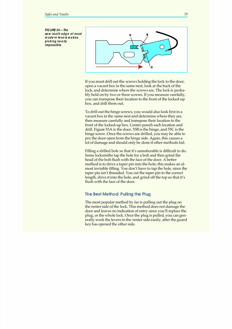
5/12/2018 10 Safes and Vaults - slidepdf.com
http://slidepdf.com/reader/full/10-safes-and-vaults-55a35b88b6c27 83/103
If you must drill out the screws holding the lock to the door,open a vacant box in the same nest, look at the back of thelock, and determine where the screws are. The lock is proba-
bly held on by two or three screws. If you measure carefully,you can transpose their location to the front of the locked-up
box, and drill them out.
To drill out the hinge screws, you would also look first in avacant box in the same nest and determine where they are,then measure carefully and transpose their location to thefront of the locked-up box. Center-punch each location anddrill. Figure 55A is the door, 55B is the hinge, and 55C is thehinge screw. Once the screws are drilled, you may be able to
pry the door open from the hinge side. Again, this causes alot of damage and should only be done if other methods fail.
Filling a drilled hole so that it’s unnoticeable is difficult to do.Some locksmiths tap the hole for a bolt and then grind thehead of the bolt flush with the face of the door. A bettermethod is to drive a taper pin into the hole; this makes an al-most invisible filling. You don’t have to tap the hole, since thetaper pin isn’t threaded. You cut the taper pin to the correctlength, drive it into the hole, and grind off the top so that it’sflush with the face of the door.
The Best Method: Pulling the Plug
The most popular method by far is pulling out the plug onthe renter side of the lock. This method does not damage thedoor and leaves no indication of entry since you’ll replace theplug, or the whole lock. Once the plug is pulled, you can gen-erally work the levers in the renter side easily, after the guardkey has opened the other side.
Safes and Vaults 79
FIGURE 54—The saw-tooth edge of most modern levers makes picking nea rly
impossible.
5/12/2018 10 Safes and Vaults - slidepdf.com
http://slidepdf.com/reader/full/10-safes-and-vaults-55a35b88b6c27 84/103
Specially-made tools are available from locksmith suppliersfor pulling either the plug or the door of safe deposit boxes.However, the tools needed are simple and many locksmithsuse their own. We’ll give instructions for using items you’resure to have in your shop: a drill, a tap, a large nut or small
block of wood, a washer, a screw, and a wing nut.
To pull the plug, drill a hole in it as shown in Figure 56. Use a#25 drill and a #10-24 tap, and make the hole about 3
8″ deep.
The goal of the next step is to pull the plug straight out so youwon’t damage the face of the door. The commercial pullersets do this well, or you can do it as well by creating a toolusing the readily-available hardware shown in Figure 57.
The plug on the guard side of the lock is shown at Figure 57A.We’re assuming that you’ve set this side of the lock with theguard key, so you won’t be touching it. Figure 57B is the plug
80 Safes and Vaults
FIGURE 55—Measure the location of the screws very ca refully before drilling.
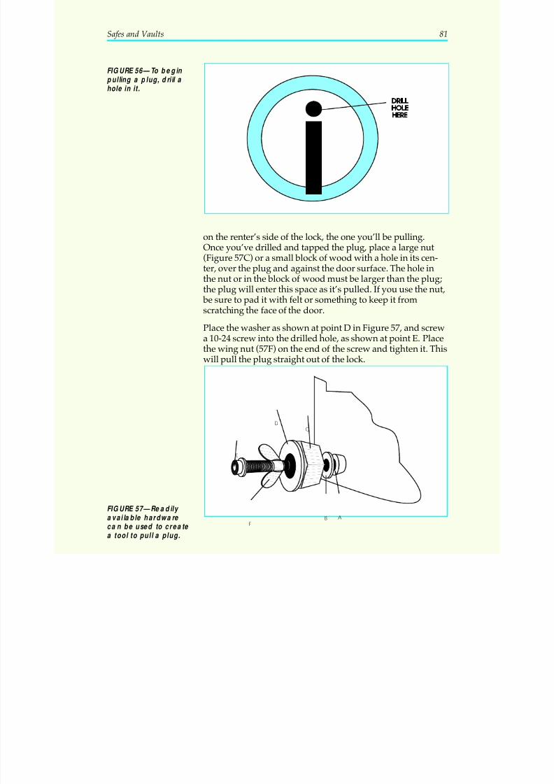
5/12/2018 10 Safes and Vaults - slidepdf.com
http://slidepdf.com/reader/full/10-safes-and-vaults-55a35b88b6c27 85/103
on the renter’s side of the lock, the one you’ll be pulling.Once you’ve drilled and tapped the plug, place a large nut(Figure 57C) or a small block of wood with a hole in its cen-ter, over the plug and against the door surface. The hole inthe nut or in the block of wood must be larger than the plug;the plug will enter this space as it’s pulled. If you use the nut,
be sure to pad it with felt or something to keep it fromscratching the face of the door.
Place the washer as shown at point D in Figure 57, and screwa 10-24 screw into the drilled hole, as shown at point E. Placethe wing nut (57F) on the end of the screw and tighten it. Thiswill pull the plug straight out of the lock.
Safes and Vaults 81
FIGURE 56—To begin pulling a plug, drill a hole in it.
E
F
D
C
B A
FIGURE 57—Readily available hardware ca n be used to create a tool to pull a plug.
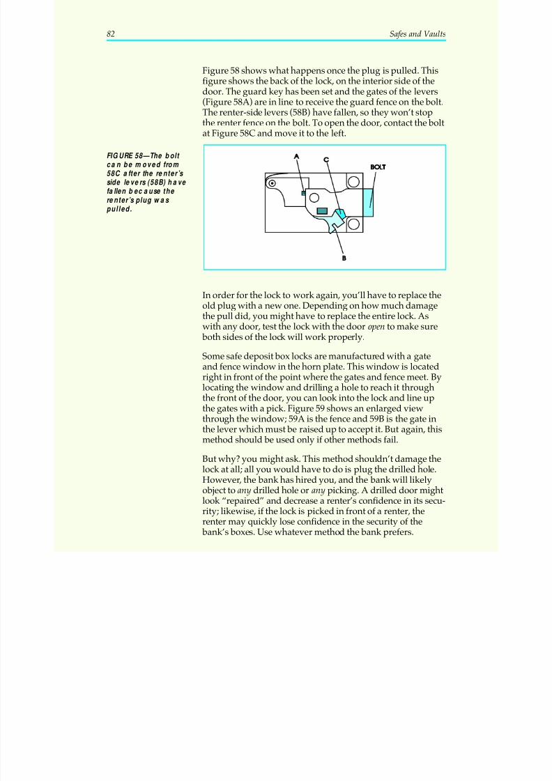
5/12/2018 10 Safes and Vaults - slidepdf.com
http://slidepdf.com/reader/full/10-safes-and-vaults-55a35b88b6c27 86/103
Figure 58 shows what happens once the plug is pulled. Thisfigure shows the back of the lock, on the interior side of thedoor. The guard key has been set and the gates of the levers(Figure 58A) are in line to receive the guard fence on the bolt.
The renter-side levers (58B) have fallen, so they won’t stopthe renter fence on the bolt. To open the door, contact the boltat Figure 58C and move it to the left.
In order for the lock to work again, you’ll have to replace theold plug with a new one. Depending on how much damagethe pull did, you might have to replace the entire lock. As
with any door, test the lock with the door open to make sure both sides of the lock will work properly.
Some safe deposit box locks are manufactured with a gateand fence window in the horn plate. This window is locatedright in front of the point where the gates and fence meet. Bylocating the window and drilling a hole to reach it throughthe front of the door, you can look into the lock and line upthe gates with a pick. Figure 59 shows an enlarged viewthrough the window; 59A is the fence and 59B is the gate inthe lever which must be raised up to accept it. But again, this
method should be used only if other methods fail.
But why? you might ask. This method shouldn’t damage thelock at all; all you would have to do is plug the drilled hole.However, the bank has hired you, and the bank will likelyobject to any drilled hole or any picking. A drilled door mightlook “repaired” and decrease a renter’s confidence in its secu-rity; likewise, if the lock is picked in front of a renter, therenter may quickly lose confidence in the security of the
bank’s boxes. Use whatever method the bank prefers.
82 Safes and Vaults
FIGURE 58—The bolt can be moved from 58C after the renter’s side levers (58B) ha ve fallen because the renter’s plug was pulled.
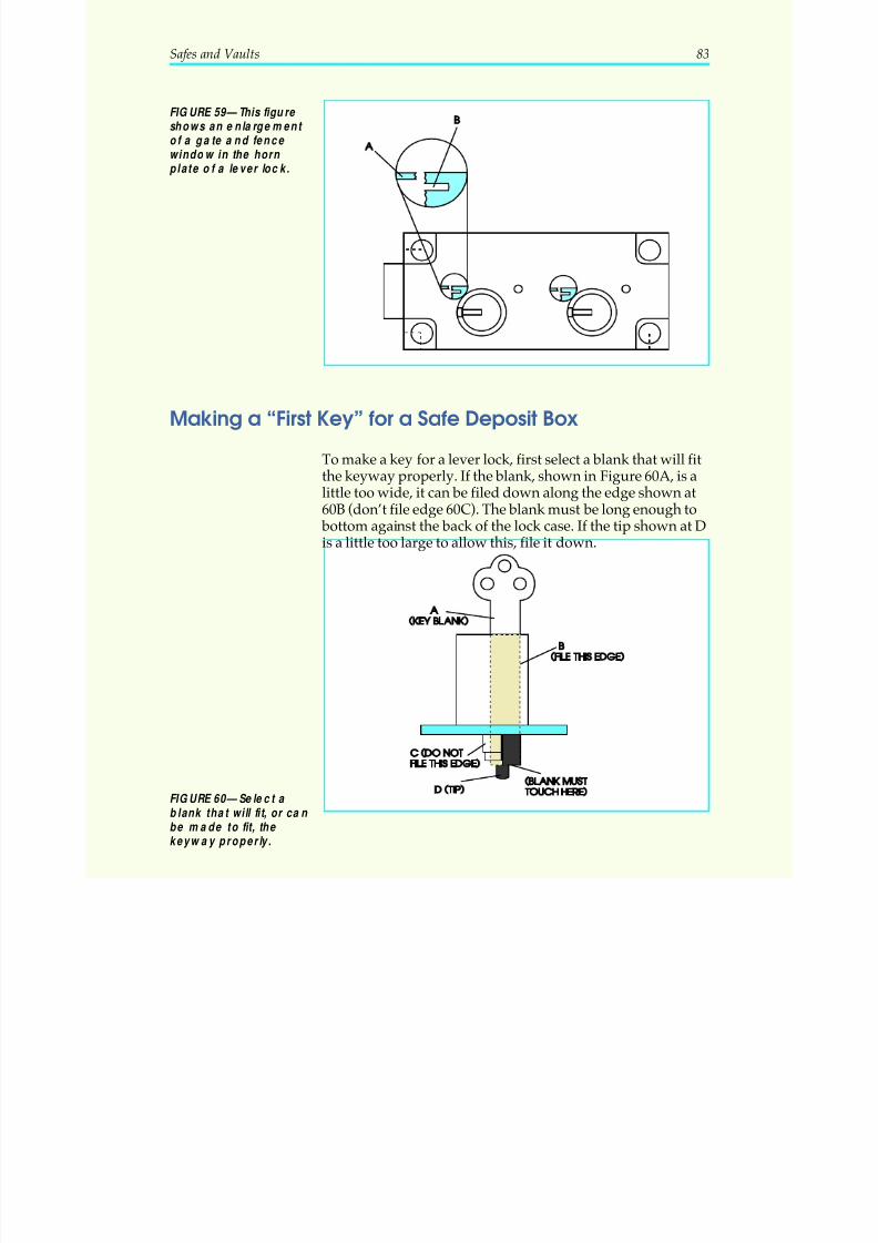
5/12/2018 10 Safes and Vaults - slidepdf.com
http://slidepdf.com/reader/full/10-safes-and-vaults-55a35b88b6c27 87/103
Making a “First Key” for a Safe Deposit Box
To make a key for a lever lock, first select a blank that will fitthe keyway properly. If the blank, shown in Figure 60A, is alittle too wide, it can be filed down along the edge shown at60B (don’t file edge 60C). The blank must be long enough to
bottom against the back of the lock case. If the tip shown at Dis a little too large to allow this, file it down.
Safes and Vaults 83
FIGURE 59—This figure shows an enlargement of a gate a nd fence window in the horn plate of a lever lock.
FIGURE 60—Select a blank that will fit, or can be made to fit, the keyway properly.
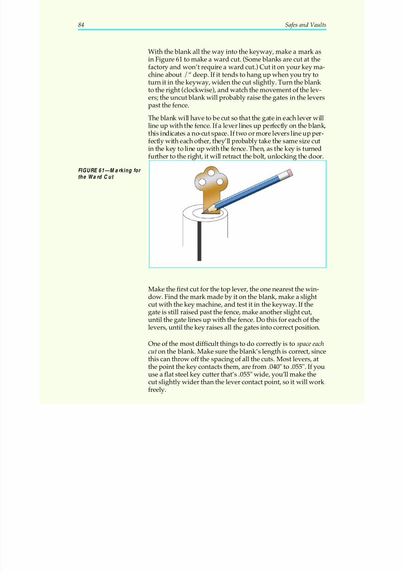
5/12/2018 10 Safes and Vaults - slidepdf.com
http://slidepdf.com/reader/full/10-safes-and-vaults-55a35b88b6c27 88/103
With the blank all the way into the keyway, make a mark asin Figure 61 to make a ward cut. (Some blanks are cut at thefactory and won’t require a ward cut.) Cut it on your key ma-chine about 1/8“ deep. If it tends to hang up when you try to
turn it in the keyway, widen the cut slightly. Turn the blank to the right (clockwise), and watch the movement of the lev-ers; the uncut blank will probably raise the gates in the leverspast the fence.
The blank will have to be cut so that the gate in each lever willline up with the fence. If a lever lines up perfectly on the blank,this indicates a no-cut space. If two or more levers line up per-fectly with each other, they’ll probably take the same size cutin the key to line up with the fence. Then, as the key is turnedfurther to the right, it will retract the bolt, unlocking the door.
Make the first cut for the top lever, the one nearest the win-dow. Find the mark made by it on the blank, make a slightcut with the key machine, and test it in the keyway. If thegate is still raised past the fence, make another slight cut,
until the gate lines up with the fence. Do this for each of thelevers, until the key raises all the gates into correct position.
One of the most difficult things to do correctly is to space eachcut on the blank. Make sure the blank’s length is correct, sincethis can throw off the spacing of all the cuts. Most levers, atthe point the key contacts them, are from .040" to .055". If youuse a flat steel key cutter that’s .055" wide, you’ll make thecut slightly wider than the lever contact point, so it will work freely.
84 Safes and Vaults
FIGURE 61—Marking for the Ward Cut
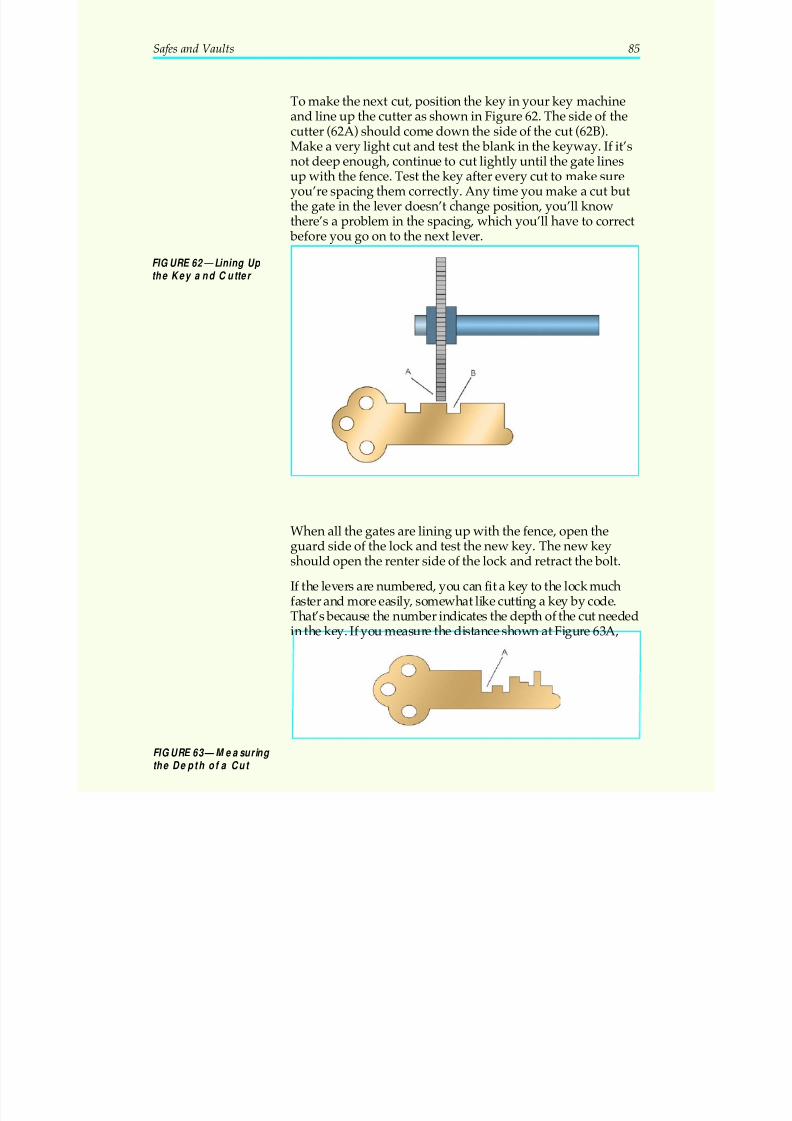
5/12/2018 10 Safes and Vaults - slidepdf.com
http://slidepdf.com/reader/full/10-safes-and-vaults-55a35b88b6c27 89/103
To make the next cut, position the key in your key machineand line up the cutter as shown in Figure 62. The side of thecutter (62A) should come down the side of the cut (62B).Make a very light cut and test the blank in the keyway. If it’s
not deep enough, continue to cut lightly until the gate linesup with the fence. Test the key after every cut to make sureyou’re spacing them correctly. Any time you make a cut butthe gate in the lever doesn’t change position, you’ll knowthere’s a problem in the spacing, which you’ll have to correct
before you go on to the next lever.
When all the gates are lining up with the fence, open theguard side of the lock and test the new key. The new keyshould open the renter side of the lock and retract the bolt.
If the levers are numbered, you can fit a key to the lock muchfaster and more easily, somewhat like cutting a key by code.That’s because the number indicates the depth of the cut needed
in the key. If you measure the distance shown at Figure 63A,
Safes and Vaults 85
FIGURE 62—Lining Up the Key and Cutter
FIGURE 63—Measuring the Depth of a Cut

5/12/2018 10 Safes and Vaults - slidepdf.com
http://slidepdf.com/reader/full/10-safes-and-vaults-55a35b88b6c27 90/103
with a micrometer on several different depths on keys you’vemade, you may uncover a pattern. A lever marked with a 1may have a depth of .350", a lever marked 2 may be .375",and a lever marked 3 may be .400"—all have a .025" differ-
ence between cuts. If you can crack the levers’ number code,you can save a lot of time by cutting “by number” on yourkey machine. This data can usually be found in code booksand key machine instruction manuals.
86 Safes and Vaults
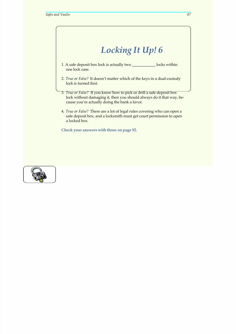
5/12/2018 10 Safes and Vaults - slidepdf.com
http://slidepdf.com/reader/full/10-safes-and-vaults-55a35b88b6c27 91/103
Safes and Vaults 87
Locking It Up! 6
1. A safe deposit box lock is actually two ____________ locks withinone lock case.
2. True or False? It doesn’t matter which of the keys in a dual-custodylock is turned first.
3. True or False? If you know how to pick or drill a safe deposit boxlock without damaging it, then you should always do it that way, be-cause you’re actually doing the bank a favor.
4. True or False? There are a lot of legal rules covering who can open asafe deposit box, and a locksmith must get court permission to opena locked box.
Check your answers with those on page 92.
5/12/2018 10 Safes and Vaults - slidepdf.com
http://slidepdf.com/reader/full/10-safes-and-vaults-55a35b88b6c27 92/103
THEKEY TO SUCCESS
Well, you’ve completed another important study unit and
you’re one step closer to your career goal. You now know agreat deal about safes, vaults, and safe deposit boxes: theirconstruction, operation, and repair. You also learned about thetechniques used to open locked safes. These skills should serveyou well in your professional career, even if you decide not tospecialize in safe work. Locksmiths should always seek to ex-pand their professional skills, since this will enable them to
better serve their customers (and advance themselves as well).
Now, read through the following Key Points to Remember. Thisreview of the important facts and concepts in the study unit will
help you retain what you’ve learned. When you feel you knowthe material well, proceed to the examination. Good luck!
KEY POINTSTO REMEMBER
Safes can be found almost everywhere, in commercial andresidential settings, and they’re used in many ways: to guardcash, important papers, firearms, and many other valuables.
Locksmiths aren’t safe and vault technicians, but the chang-ing of safe combinations and the servicing of locks and safesare very much a part of a locksmith’s business.
A safe’s fire-resistance or burglary-resistance determineswhat materials you’ll find inside it. We covered the functionof relockers and hardplates, how to determine the make andmodel number of a safe, and what the “hand” of the lock is.We also looked at how the combination lock works in factand in theory — how many possible combinations there areon any given lock, and so forth — which makes it the ingen-
iously secure device that it is.
Changing the combination is one of the most common serv-ices a locksmith performs on a “safe call.” Although it’s com-mon, it should never become “routine”! Combinationchanging is a very delicate job which requires much skill. Amistake on even a very simple lock can cause a lockout. Inthis study unit, we examined the two main types of locks:hand-changing, and key-changing. Of the hand-changinglocks, we examined the hole-type, screw-type, and mesh-type
88 Safes and Vaults
5/12/2018 10 Safes and Vaults - slidepdf.com
http://slidepdf.com/reader/full/10-safes-and-vaults-55a35b88b6c27 93/103
wheels and how to change their combinations neatly andproficiently. We looked at how the key-changing lock works,and the correct procedure for changing its combination bykey. Last but not least, we learned what combination num-
bers are best not to use, and why.
When setting or changing a combination, don’t concentrateon just the lock alone. Of course, it’s very important to have asmoothly functioning lock. In this study unit, you learnedhow to properly clean and service the combination lock. Youlearned what to look for, like dirt, burrs, or worn parts that cancause the lock to malfunction, and how to correct them. Youmay have the lock working perfectly, however, and the safemay still lock up if the rest of the door isn’t serviced. It’s difficult
to convince a customer with a locked safe that the lock itself isworking properly! Safeguard your professional reputation bylubricating the boltworks, making sure screws are tight, and fol-lowing the other service points outlined in this text.
Movies have made safe opening look easy, but in reality it’snot. A major factor in getting a locked safe open is the answerto this question: Is the combination known? By using thetroubleshooting techniques outlined here, you may pop openthe safe to the owner’s amazement. If the safe has been bur-glarized, you now know what conditions to look for, includ-
ing evidence of an unexploded charge, before you beginworking on the safe. If the combination is unknown, drillingthe safe may be the only choice. You know basically howdrilling works in getting a locked safe open, and how torepair the safe door so that it’s as good as new. Drilling is aspecialized skill that brings the locksmith into safe and vaulttechnicians’ territory. For more information on becoming atechnician, you may wish to contact the Safe and Vault Tech-nicians Association (SAVTA) at 3003 Live Oak Street, Dallas,TX 75204-6186.
Many locksmiths would add safe deposit box work to their business, if they understood the concept of the lever lock bet-ter. Safe deposit box locks are dual-custody locks that com-
bine two lever locks within one lock case. In this study unit,you learned the correct terminology for these locks, and howthey work. You learned how banks and renters use safe de-posit boxes, and why it requires a key from each to open thelock. You learned how to deal with the bank in changing thelocks and duplicating keys.
Safes and Vaults 89
5/12/2018 10 Safes and Vaults - slidepdf.com
http://slidepdf.com/reader/full/10-safes-and-vaults-55a35b88b6c27 94/103
Do You Know Now . . .
What is the locksmith’s“golden rule” for working with safes?
The loc ksmith’ s “ g olde n rule” for wo rking w ith sa fes is: Alw a ys test your wo rk with the
door open. Never shut a safe or vault door and then see if you c an unlock it!
What two servicesdo locksmithsperform most often on safes?
The two services tha t loc ksmithsperform most often on safes are (1) changing the
combination on the c ombination loc k, and (2) troub leshooting, cleaning, and re-
pa iring the c ombination loc k and safe door.
How are burgalar-resistant and fire-resistant safes different?
The ma terialsa nd c onstruction of a sa fe’s do or and b od y will depend on whe therthe safe ismeant to be fire-resistant or burglar-resistant. Burglar-resista nt safes are
often ma de of solid stee l, or of a conc rete -like com pound sandwiched b etween
thick shee ts of stee l. They have spec ia l sec urity fea tures, suc h as rec essed doo rs
and hea vy-duty hinges tha t resist prying a nd hamm ering. Fire-resistant safes have
doorsand bodiesmade mostly of a fireproof compound encased in sheet steel.
The firep roo f ma teria l shields the interior from hea t, protec ting the c ontents of the
safe.
90 Safes and Vaults
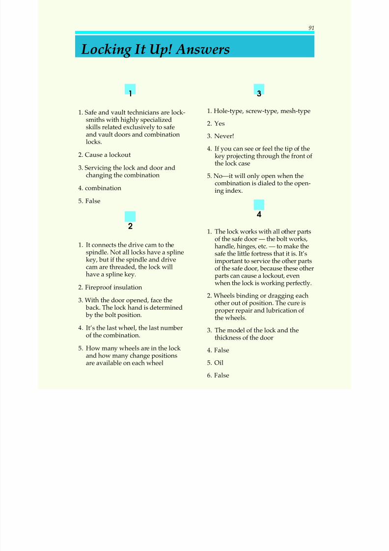
5/12/2018 10 Safes and Vaults - slidepdf.com
http://slidepdf.com/reader/full/10-safes-and-vaults-55a35b88b6c27 95/103
1
1. Safe and vault technicians are lock-smiths with highly specializedskills related exclusively to safeand vault doors and combinationlocks.
2. Cause a lockout
3. Servicing the lock and door andchanging the combination
4. combination
5. False
2
1. It connects the drive cam to thespindle. Not all locks have a splinekey, but if the spindle and drivecam are threaded, the lock willhave a spline key.
2. Fireproof insulation
3. With the door opened, face the back. The lock hand is determined by the bolt position.
4. It’s the last wheel, the last numberof the combination.
5. How many wheels are in the lock and how many change positionsare available on each wheel
3
1. Hole-type, screw-type, mesh-type
2. Yes
3. Never!
4. If you can see or feel the tip of the
key projecting through the front of the lock case
5. No—it will only open when thecombination is dialed to the open-ing index.
4
1. The lock works with all other partsof the safe door — the bolt works,handle, hinges, etc. — to make thesafe the little fortress that it is. It’simportant to service the other partsof the safe door, because these otherparts can cause a lockout, evenwhen the lock is working perfectly.
2. Wheels binding or dragging eachother out of position. The cure is
proper repair and lubrication of the wheels.
3. The model of the lock and thethickness of the door
4. False
5. Oil
6. False
Locking It Up! Answers
91
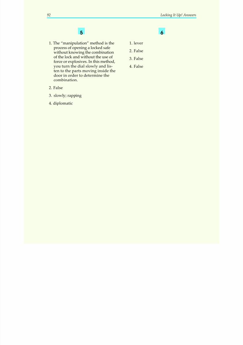
5/12/2018 10 Safes and Vaults - slidepdf.com
http://slidepdf.com/reader/full/10-safes-and-vaults-55a35b88b6c27 96/103
5
1. The “manipulation” method is the
process of opening a locked safewithout knowing the combinationof the lock and without the use of force or explosives. In this method,you turn the dial slowly and lis-ten to the parts moving inside thedoor in order to determine thecombination.
2. False
3. slowly; rapping4. diplomatic
6
1. lever
2. False
3. False
4. False
92 Locking It Up! Answers
5/12/2018 10 Safes and Vaults - slidepdf.com
http://slidepdf.com/reader/full/10-safes-and-vaults-55a35b88b6c27 97/103
Safes and Vaults
When you feel confident that you have mastered the material in this study unit, com-plete the following examination. Then submit only your answers to the school for grading, using one of the examination answer options described in your “Test Materi-als” envelope. Send your answers for this examination as soon as you complete it.Do not wait until another examination is ready.
Questions 1–20: Select the one best answer to each question.
1. What is the main cause of most lockouts?
A. A breakdown in one of the parts in the lock or safe doorB. Wheels binding or dragging each other out of positionC. Losing or forgetting the combination numberD. A mistake in changing the combination
2. What is the best way to prevent the most common type of safe lockout?
A. Proper maintenance and lubrication C. Careful training and practiceB. Better manufacturing techniques D. Not abusing the lock
Examination 93
EXAMINATION NUMBER:
03101000
Whichever method you use in submitting your exam
answers to the school, you must use the number above.
For the quickest test results, go tohttp://www.takeexamsonline.com
5/12/2018 10 Safes and Vaults - slidepdf.com
http://slidepdf.com/reader/full/10-safes-and-vaults-55a35b88b6c27 98/103
3. Most people purchase safes to protect against which of the following?
A. Fire and burglary C. Explosives and burglary toolsB. Fire and natural disasters D. Water and smoke damage
4. Imagine that you’re called to a lockout. The safe owner tells you that the first number ofthe combination is 13, but that he is unsure of the other two numbers. You check thearea around the safe, but can’t find the combination written anywhere. You learn that theowner’s birthday is April 13, 1961, and his address is 1339 First Avenue. The safe waspurchased last December but has never been serviced. What group of numbers wouldyou try first on the lock to see if it will open?
A. 13-13-13 and 4-4-4 C. 1-1-1 and the current dateB. 4-19-61 and 12-12-12 D. 13-4-61 and 13-39-1
5. A fire-resistant safe will have a door and body made mainly of
A. solid steel.B. solid iron.C. fireproof insulation encased in sheet steel.D. fireproof insulation only.
6. A safe with a high burglar-resistant rating will probably have
A. a removable dial.B. a solid steel door, a relocking device, and a hardplate.C. fireproof insulation in the door.
D. a medium-security lock with no relocker.
7. The purpose of a hardplate in a safe door is to
A. guard the lock and bolt mechanism from drill attacks.B. make the safe door more fireproof.C. make the safe door stronger.D. make the safe more watertight.
8. In any combination lock (whether two-wheel, three-wheel, etc.) the wheel next to thedrive cam is
A. the first wheel, and the first number of the combination.B. the last wheel, and the last number of the combination.C. the drive wheel.D. the fly wheel.
94 Examination
5/12/2018 10 Safes and Vaults - slidepdf.com
http://slidepdf.com/reader/full/10-safes-and-vaults-55a35b88b6c27 99/103
Questions 9 and 10 are based on the following scenario.
A safe owner is having trouble with a right-hand, three-wheel lock. You’re told that thecombination is 25-50-75. The owner first turns the dial three complete revolutions to the
left (counterclockwise), stopping at 0, then dials the proper numbers. Although eachnumber is dialed to the changing index slowly and carefully, the door still won’t open.
9. What is the first thing the safe owner did wrong?
A. The owner needs to make four complete revolutions to the left, not three.B. The owner needs to make three complete revolutions to the right, not to the left.C. The owner should dial the combination to the opening index, not to the changing
index.D. The owner must have gotten the combination numbers reversed.
10.What is the second thing the safe owner did wrong?
A. The owner needs to make four complete revolutions to the left, not three.B. The owner needs to make three complete revolutions to the right, not to the left.C. The owner should dial the combination to the opening index, not to the changing
index.D. The owner must have gotten the combination numbers reversed.
11. You have a three-wheel, hole-change lock whose dial reads from 0 to 100. Two of thewheels have 10 holes in which the drive pins can be placed; the third wheel has only 5holes. How many combinations are possible?
A. 50 C. 1,000B. 500 D. 1,000,000
12.What is the drop-in point?
A. The number on the dial corresponding to where the fence drops into the gates of allof the wheels
B. The number on the dial at which a lock might malfunctionC. The point at which both locks in a dual-custody lock can openD. The point at which nitroglycerine is poured in to blow a safe
13. When changing a combination, what numbers and series of numbers should you not use?
A. Numbers too easily guessed, like the owner’s birthdate or street addressB. Numbers that rise and fallC. Numbers that mean nothing to the owner of the safeD. Numbers that are far apart on the dial
Examination 95
5/12/2018 10 Safes and Vaults - slidepdf.com
http://slidepdf.com/reader/full/10-safes-and-vaults-55a35b88b6c27 100/103
14. Watch out! There might be an unexploded charge in a burglarized safe if
A. the hinges are sawed in half.B. the dial and/or handle are missing.
C. there is soap or some kind of waterproof putty in or around the safe.D. the safe is on its side.
15. Before you begin to work on a burglarized safe, the first thing to find out is:
A. Are the police finished with their investigation of the scene?B. Did the police find any fingerprints?C. Is the combination known?D. Is the safe door open?
16. A locked safe should be drilled
A. only if the lockout is temporary.B. only if other methods fail.C. at the first sign of trouble.D. only if the owner doesn’t care if the safe’s security and value is decreased.
17. What feature of modern safe deposit box locks makes picking nearly impossible?
A. The number of levers in both the guard and renter’s sides of the lockB. The number of possible combinationsC. The number of keys neededD. Saw-tooth edges of levers and fences
18. Which of the following are the two rules to follow in opening locked safe deposit boxes?
A. (1) Use the opening method preferred by the bank, and (2) do not damage or defacethe door.
B. (1) Use the opening method you know will work best, and (2) do not damage ordeface the door.
C. (1) Use the opening method you know will work best, and (2) do not damage thelock.
D. (1) Pick the lock, and (2) do this without the renter present.
19. What is the preferred method for getting a locked safe deposit box open?
A. Pull the plugs out of the renter’s and the guard sides of the lock.B. Drill for the gate-and-fence window built into the lock.C. Pull the plug out of the renter’s side of the lock.D. Drill out the hinge screws.
96 Examination

5/12/2018 10 Safes and Vaults - slidepdf.com
http://slidepdf.com/reader/full/10-safes-and-vaults-55a35b88b6c27 101/103
20. In making a key for a lever lock, one of the most difficult things to do is to
A. space the cuts correctly along the blank.B. cut the blank to the right length.
C. cut the ward.D. make the renter key different from the guard key.
Examination 97

5/12/2018 10 Safes and Vaults - slidepdf.com
http://slidepdf.com/reader/full/10-safes-and-vaults-55a35b88b6c27 102/103
NOTES
98 Examination

5/12/2018 10 Safes and Vaults - slidepdf.com
http://slidepdf.com/reader/full/10-safes-and-vaults-55a35b88b6c27 103/103
COMING ATTRACTIONS
In your next study unit, you’ll be introduced to electric locks
and panic hardware. These important security devices arewidely used in commercial businesses and public institutionswhere the safety of large groups of people is a major concern.You’ll start by learning about basic electrical concepts; thenyou’ll move on to the construction and installation of electriclocks and panic devices. Good luck with your continuingstudies!
Safes and Vaults 99