10. Radiation Heat Transfer - cu B-10.pdf · Part B: Heat Transfer Principals in Electronics...
12
Part B: Heat Transfer Principals in Electronics Cooling 98 MPE 635: Electronics Cooling 10. Radiation Heat Transfer 10.1 Introduction Radiation heat transfer plays a major role in the cooling of electronics. As well as conduction and convection heat transfer, radiation is an equally important mode. Also the thermal radiation has many applications such as engine cooling, furnaces, boilers, piping and solar radiation. The thermal radiation transferred by electromagnetic waves, called photons, is emitted by bodies due to temperature differences. All surfaces continuously emit and absorb radiative energy by lowering or raising their molecular energy levels. The electromagnetic waves travel through any medium or in vacuum at the speed of light (c), which equals 3 10 8 m/s. this speed equal to the product of the wave length and frequency c = The metric unit for the wave length is centimeters or angstroms (1 angstrom = 10 -8 centimeter). A portion of the electromagnetic spectrum is shown in Figure 10.1. 10 -5 10 -4 10 -3 10 -2 10 -1 1 10 10 2 10 3 10 4 Gamma rays X rays ultraviolet Thermal radiation Infrared Microwave Red yellow Blue Green Vis ible λ (µ m) Figure 10.1 Electromagnetic spectrum 10.2 Blackbody Radiation Materials used in electronic hard ware may be classified as black or gray surfaces. The ideal surface is known as a “blackbody” or “black surface,” since it absorbs or emits 100% of the all incoming radiation. A rough surface has higher emittance than the same surface when it is smooth. Also, a finned surface has a higher emittance than does the same surface without fins. In both cases the emittance increases because the surfaces have many small cavities. These cavities act as many small partial black bodies. For example a small hole in a hollow sphere is often used to represent a black body. The energy enters the small opening and strikes the opposite wall, where part of the energy is absorbed and part is reflected. The reflected energy again strikes the opposite wall, where part of the energy is absorbed and part is
Transcript of 10. Radiation Heat Transfer - cu B-10.pdf · Part B: Heat Transfer Principals in Electronics...

Part B: Heat Transfer Principals in Electronics Cooling
98MPE 635: Electronics Cooling
10. Radiation Heat Transfer
10.1 Introduction Radiation heat transfer plays a major role in the cooling of electronics. As well as conduction and convection heat transfer, radiation is an equally important mode. Also the thermal radiation has many applications such as engine cooling, furnaces, boilers, piping and solar radiation. The thermal radiation transferred by electromagnetic waves, called photons, is emitted by bodies due to temperature differences. All surfaces continuously emit and absorb radiative energy by lowering or raising their molecular energy levels. The electromagnetic waves travel through any medium or in vacuum at the speed of light (c), which equals 3 �108 m/s. this speed equal to the product of the wave length � and frequency �
c =�� The metric unit for the wave length � is centimeters or angstroms (1 angstrom = 10-8 centimeter). A portion of the electromagnetic spectrum is shown in Figure 10.1.
10-5 10-4 10-3 10-2 10-1 1 10 102 103 104
Gamma rays
X rays ultraviolet
Thermal radiation
InfraredMicrowave
RedyellowBlueGreen
Visible
λ (µm)
Figure 10.1 Electromagnetic spectrum 10.2 Blackbody Radiation Materials used in electronic hard ware may be classified as black or gray surfaces. The ideal surface is known as a “blackbody” or “black surface,” since it absorbs or emits 100% of the all incoming radiation. A rough surface has higher emittance than the same surface when it is smooth. Also, a finned surface has a higher emittance than does the same surface without fins. In both cases the emittance increases because the surfaces have many small cavities. These cavities act as many small partial black bodies. For example a small hole in a hollow sphere is often used to represent a black body. The energy enters the small opening and strikes the opposite wall, where part of the energy is absorbed and part is reflected. The reflected energy again strikes the opposite wall, where part of the energy is absorbed and part is

Part B: Heat Transfer Principals in Electronics Cooling
99MPE 635: Electronics Cooling
reflected. This process continues until all of the energy is absorbed, as shown in Figure10.2. The total amount of radiative energy emitted from a surface into all directions above it is termed emissive power; we distinguish between spectral (at a given wavelength �, per unit wavelength and per unit surface area) and total (encompassing all wavelengths) emissive power. The magnitude of emissive power depends on wavelength �, temperature T, and a surface property, called emissivity �, which relates the ability of a surface to emit radiative energy to that of an ideal surface, which emits the maximum possible energy (at a given wavelength and temperature). The spectral distribution of the emissive power Eλ,b of a black surface is given by Planck’s law is of the form
]1[ )/(51
, 2 −= TCb e
CE λλ λ
Where the radiation constants or some times called Planck function constants are C1= 3.742 x10⁸ W.µm4/m2 and C2=1.439 x104 µm.k. The total emissive power Eb of a blackbody is given by Stefan-Boltzmann law. Expressed as
,0
b bE E dλ λ∞
= ∫
Integration yields; Eb = σT4
Where the temperatures in the Kelvin's and the Stefan-Boltzmann constant (σ) has the numerical value σ = 5.67 x 10⁻⁸ W/m2.K
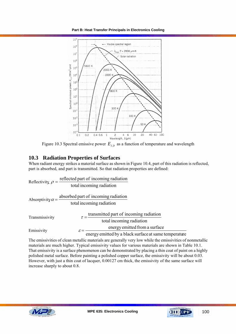
Figure 10.2 Constructing a black body enclosure Figure 10.3 shows the spectral emissive power Eλ,b as a function of temperature and wavelength, the maximum Eλ,b is corresponding to wave length λmax which depends on surface temperature. The nature of this dependence may be obtained by differentiating the Equation 10.1 with respect to λ and setting the result equal to zero, we obtain
λmax T = 2897.6 µm.K The Equation 10.3 is known as Wien's displacement law.
(10.1)
(10.2)
(10.3)
Part B: Heat Transfer Principals in Electronics Cooling
100MPE 635: Electronics Cooling
Figure 10.3 Spectral emissive power bE ,λ as a function of temperature and wavelength
10.3 Radiation Properties of Surfaces When radiant energy strikes a material surface as shown in Figure 10.4, part of this radiation is reflected, part is absorbed, and part is transmitted. So that radiation properties are defined:
Reflectivity radiation incoming total
radiation incoming ofpart reflected=ρ
Absorptivity radiation incoming total
radiation incoming ofpart absorbed=α
Transmissivity radiation incoming total
radiation incoming ofpart dtransmitte=τ
Emissivity re temperatusameat surfaceblack aby emittedenergy
surface a from emittedenergy =ε
The emissivities of clean metallic materials are generally very low while the emissivities of nonmetallic materials are much higher. Typical emissivity values for various materials are shown in Table 10.1. That emissivity is a surface phenomenon can be demonstrated by placing a thin coat of paint on a highly polished metal surface. Before painting a polished copper surface, the emissivity will be about 0.03. However, with just a thin coat of lacquer, 0.00127 cm thick, the emissivity of the same surface will increase sharply to about 0.8.

Part B: Heat Transfer Principals in Electronics Cooling
101MPE 635: Electronics Cooling
Absorption
Incident radiation Reflection
Transmission
Figure 10.4 Reflection, absorption, and transmission
Since all radiation striking a body must be reflected, absorbed, or transmitted, it follows that
�1 In some practical applications surface layers are thick enough to be opaque then the transmissivity may be taken as zero. All four properties may be functions of wavelength, temperature, incoming direction (except emissivity), and outgoing direction (except absorptivity). Table 10.1 Typical emissivities at 100 oC Material Emissivity Aluminum
6 Commercial sheet 0.09 Rough polish 0.07 Gold, highly polished 0.018-0.035 Steel, polished 0.06 Iron, polished 0. 14-0.38 Cast iron, machine cut 0.44 Brass, polished 0.06 Copper, polished 0.023-0.052 Polished steel casting 0.52-0.56 Glass, smooth 0.85-0.95 Aluminum oxide 0.33 Anodized aluminum 0.81 Black shiny lacquer on iron 0.8 Black or white lacquer 0.8-0.95 Aluminum paint and lacquer 0.52 Rubber, hard or soft 0.86-0.94
(10.4)

Part B: Heat Transfer Principals in Electronics Cooling
102MPE 635: Electronics Cooling
Two types of reflection phenomena may be observed when radiation strikes a surface. The reflection is called specular if the angle of incidence is equal to the angle of reflection as shown in Figure 10.5(a), the reflection is called diffuse when the incident beam is distributed uniformly in all directions after reflection as shown in Figure 10.5(b).No real surface is either specular or diffuse. An ordinary mirror is quite specular for visible light, but would not necessarily be specular over the entire wave length range of thermal radiation. Ordinarily, a rough surface exhibits diffuse behavior better than polished surface. Similarly, a polished surface is more specular than a rough surface.
Source
Reflected raysΦ ΦSource Reflected
(a) (b)
Figure 10.5 (a) Specular reflection (b) Diffuse reflection
10.4 Kirchhoff's Law Assume that a perfectly black enclosure is available, i.e., one which absorbs all the incident radiation falling upon it, as shown in Figure10.6.
A
Black enclosure
qiαBody
E
Figure10.6 Model used for deriving Kirchhoff's law
This enclosure will also emit radiation according to the T4 law. The radiant flux arriving at a given area inside the enclosure is qi W/m2. Now suppose that a body is placed inside the enclosure until it reaches equilibrium. At equilibrium the energy absorbed must be equal to the energy emitted. The radiation absorbed by the body = qiα A The radiation emitted from the body = EA At equilibrium
EA = qiα A If the body is replaced by a black body (α =1) with the same area and shape and allowed to equilibrium at the same temperature.
Eb A = qiA
(10.5)
(10.6)

Part B: Heat Transfer Principals in Electronics Cooling
103MPE 635: Electronics Cooling
If the Equation 10.5 is divided by Equation 10.6 it yields
α = E / Eb This ratio is the emissive power of a body to the emissive power of a black body at same temperature. It is also defined before as the emissivity(ε) of the body. So that, for any surface inside enclosure α = E / Eb = ε The Equation 10.7 is called Kirchhoff's law. 10.5 Radiation between Black Surfaces and Shape Factors The shape factor Fij is the fraction of radiant energy leaving one surface that is intercepted by another surface; other names for the shape factor are view factor, angle factor, and geometrical factor. To develop a general expression for Fij, consider two black surfaces has A1 and A2 as shown in Figure 10.7.When the two surfaces are maintained at different temperature we want to determine the amount of energy which leaves one surface to another. Firstly we define the shape factor as F1-2 = Fraction of radiation leaving A1 arriving at A2 F2-1 = Fraction of radiation leaving A2 arriving at A1
ϕ 2
ϕ 1
dA2
dA1
A2
A1
r
Figure 10.7 Model for deriving radiation shape factor
The energy leaving surface 1 and arriving at surface2 is
q1-2 = A1F12 Eb1 The energy leaving surface 2 and arriving at surface1 is
q2-1= A2F21 Eb2 The net energy exchange is
qnet = A1F12 Eb1- A2F21 Eb2 If the two surfaces are at same temperatures, there would not be heat exchange between them so that qnet equals to zero. In this case Equation10.8 will be
A1F12 Eb1 = A2F21Eb2 Also at same temperatures: Eb1 = Eb2 which simplify Equation10.9 to
A1F12 = A2F21 For general expression for any two surfaces i and j:
(10.7)
(10.8)
(10.10)
(10.11)
(10.9)

Part B: Heat Transfer Principals in Electronics Cooling
104MPE 635: Electronics Cooling
AiFij = AjFji Equation 10.11 is known as the reciprocity relation Considering the elements dA1 and dA2 as shown in Figure 10.7, the energy leaving surface dA1 and arriving at surface dA2 is
dwdAEdq b11
121 cosϕ
π=−
Where dw is the solid angle subtended by dA2 when viewed from dA1, its mathematical expression is:
222
22
rcos
r centersbetween line on thedA of Projection ϕdAdw =
=
Substituting in Equation 10.12 gives
212211
21coscos dAdA
rEdq b
πϕϕ
=−
Similarly the energy leaving surface dA2 and arriving at surface dA1 is
212122
12coscos dAdA
rEdq b
πϕϕ
=−
The net energy exchange between dA1 and dA2 is
( )21122
21
1221
coscos dAdArEEdqdqdq
bb
net
ϕϕπ
−=
−= −−
Performing double integration on Equation 10.14 with respect to A1 and A2 yields
( ) ∫∫−=12
22112
21coscos
AAbbnet r
dAdAEEqπ
ϕϕ
But
∫∫==12
22112
212121coscos
AA rdAdA
FAFAπ
ϕϕ
This gives
( )
( )( ) 212
42
41
21221
12121
FATT
FAEE
FAEEq
bb
bbnet
−=
−=
−=
σ
A few graphical results that present the shape factor for important geometries are shown in Appendix A. But For nontrivial geometries shape factors must be calculated by double integration of Equation10.16. 10.6 Shape Factor Relations Some important shape factor relations are suggested below. 10.6.1 Reciprocity Relation
(10.12)
(10.13)
(10.14)
(10.17)
(10.15)
(10.16)

Part B: Heat Transfer Principals in Electronics Cooling
105MPE 635: Electronics Cooling
As explained before during previous derivations, this relation is useful in determining one shape factor from knowledge of the other.
AiFij = AjFji 10.6.2 Summation Rule
11
=∑=
N
jijF
Note that the term Fii is non zero if the surface is concave because it sees it self and equal zero for a plane or convex surface. This role is applied on enclosures surfaces. Example 10.1: Determine the view factor F12 for the Figure shown below knowing that D1 = D2 = 5 cm and a = 8 cm.
3
2
1 Solution:
For an enclosure 11 12 131
= 1N
ijj
F F F F=
+ + =∑
Where F11 = 0 From Figure A.1 at r1/a = r2/a = 5/8 = 0.625
∴ F13 = 0.22 Then
F12 = 1 - F13 = 1- 0.22 = 0.78 Example 10.2: Determine the view factor F12 and F13 for the figure shown below knowing that the angles α1 = α2.
α1α2
1
23
(10.18)
Part B: Heat Transfer Principals in Electronics Cooling
106MPE 635: Electronics Cooling
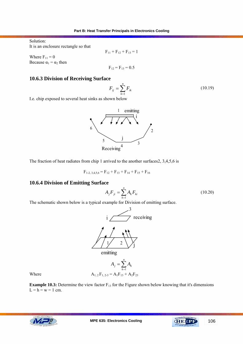
Solution: It is an enclosure rectangle so that
F11 + F12 + F13 = 1 Where F11 = 0 Because α1 = α2 then
F12 = F13 = 0.5 10.6.3 Division of Receiving Surface
∑=
=n
kikij FF
1
I.e. chip exposed to several heat sinks as shown below
1
2
345
6
emitting
Receiving
i
j
The fraction of heat radiates from chip 1 arrived to the another surfaces2, 3,4,5,6 is F1-2, 3,4,5,6 = F12 + F13 + F14 + F15 + F16 10.6.4 Division of Emitting Surface
∑=
=n
kkikjij FAFA
1
The schematic shown below is a typical example for Division of emitting surface.
1 2
3
emitting
receivingi
j
∑=
=n
kkj AA
1
Where A1, 2 F1, 2-3 = A1F13 + A2F23
Example 10.3: Determine the view factor F13 for the Figure shown below knowing that it's dimensions L = h = w = 1 cm.
(10.19)
(10.20)

Part B: Heat Transfer Principals in Electronics Cooling
107MPE 635: Electronics Cooling
A1
A2
A3
L
h/2
wh/2
Solution: By taking the areas A1and A2 with A3 and using Equation 10.19 to gives
F3-1, 2 = F31 + F32 From Figure A.3 at W = 1 and H = 1
∴F3-1, 2= 0.2 By taking the areas A2 with A3 and from Figure A.3 at H = 0.5 and W = 1
∴F32 = 0.15 Substitute in main equation to gives
F31= 0.2 – 0.15= 0.05 By using reciprocity relation A3F31=A1F13 Then ∴F13 = 0.1

Part B: Heat Transfer Principals in Electronics Cooling
108MPE 635: Electronics Cooling
Appendix A
Figure A.1 View factor between parallel, coaxial disks of unequal radius
Figure A.2 View factor between identical, parallel, directly opposed rectangles

Part B: Heat Transfer Principals in Electronics Cooling
109MPE 635: Electronics Cooling
Figure A.3 View factor between perpendicular rectangles with common edge