![UH-1 Huey-Slicks 1962-75 [Osprey New Vanguard 087]](https://static.fdocuments.in/doc/165x107/552bad354a7959ff7c8b4573/uh-1-huey-slicks-1962-75-osprey-new-vanguard-087.jpg)
1.0. Purpose of Planningsurvivalbooksonline.com/library/survival_military... · 2017-02-21 · 3.1....
32
Plan Coordination of Munition Deliveries MP10A-TATS 1 1.0. Purpose of Planning The most important process in sling-out operations is prior planning. Prior planning, along with the coordination of plans with the aviation liaison officer, is essential for a smooth, safe operation. During the planning phase, all aspects of the mission are reviewed, including aircraft limitations, landing site selection, items to be lifted, and the weight of items to be lifted. For example, since helicopter lift capacity may change in response to environmental conditions, coordination with the aviation unit is essential. If a particular item of equipment presents a problem that cannot be resolved, it should be referred to the operations department/section of the participating unit, or another mode of transportation should be considered. At a minimum, the following planning factors must be considered: Number of ground crew personnel Equipment to be transported (for example, weight, size, quantity, and destination) Alternate means of transportation available Number of aircraft and sorties required Landing site and required delivery time Special lifting devices required Primary and alternate radio frequencies and quantity of radios required Ground crew and aircraft emergency procedures Review of maps, landing site description, and local terrain features Safety hazards Landing site condition and security Training requirements. 2.0. Personnel Requirements The number of ground crew personnel needed for sling-out operations depends primarily on how the commander plans to accomplish a given mission. Selected personnel or all unit members may be trained as ground crew members. Other factors to consider are The quantity and type of equipment to be externally transported The number of aircraft available The amount of time the unit has to relocate or resupply other units The frequency with which the unit will transport equipment/munitions by helicopter. 2.1. Ground Crew Requirements Ground crew teams are classified by their locations: the hookup team (at the supported unit landing site) and the receiving team (at the receiving unit site). The hookup team consists of at least three persons: the signalman, the static wand person, and the hookup man. Additional hookup men are required when dual and multiple-hook aircraft,
Transcript of 1.0. Purpose of Planningsurvivalbooksonline.com/library/survival_military... · 2017-02-21 · 3.1....

Plan Coordination of Munition Deliveries MP10A-TATS
1
1.0. Purpose of Planning
The most important process in sling-out operations is prior planning. Prior planning, along with the coordination of plans with the aviation liaison officer, is essential for a smooth, safe operation. During the planning phase, all aspects of the mission are reviewed, including aircraft limitations, landing site selection, items to be lifted, and the weight of items to be lifted. For example, since helicopter lift capacity may change in response to environmental conditions, coordination with the aviation unit is essential. If a particular item of equipment presents a problem that cannot be resolved, it should be referred to the operations department/section of the participating unit, or another mode of transportation should be considered.
At a minimum, the following planning factors must be considered:
Number of ground crew personnel Equipment to be transported (for example, weight, size, quantity, and destination) Alternate means of transportation available Number of aircraft and sorties required Landing site and required delivery time Special lifting devices required Primary and alternate radio frequencies and quantity of radios required Ground crew and aircraft emergency procedures Review of maps, landing site description, and local terrain features Safety hazards Landing site condition and security Training requirements.
2.0. Personnel Requirements
The number of ground crew personnel needed for sling-out operations depends primarily on how the commander plans to accomplish a given mission. Selected personnel or all unit members may be trained as ground crew members. Other factors to consider are
The quantity and type of equipment to be externally transported The number of aircraft available The amount of time the unit has to relocate or resupply other units The frequency with which the unit will transport equipment/munitions by helicopter.
2.1. Ground Crew Requirements
Ground crew teams are classified by their locations: the hookup team (at the supported unit landing site) and the receiving team (at the receiving unit site).
The hookup team consists of at least three persons: the signalman, the static wand person, and the hookup man. Additional hookup men are required when dual and multiple-hook aircraft,
Plan Coordination of Munition Deliveries MP10A-TATS
2
such as the CH-47D and H-53E, are used. The H-53E requires a separate wand person for each cargo hook, while the CH-47D requires only a single static wand person.
The receiving team consists of a signalman to direct the placement of the load, a hookup man who is familiar with manual release procedures, and when required, a static wand person. The hookup man and static wand person are necessary when the cargo hook has to be opened manually.
Since the unit owning the equipment is responsible for properly rigging the equipment and using correct procedures during the sling load operation, the ground crew must be thoroughly trained in the complete operation. Ground crew duties include:
Clearing the landing site Rigging and derigging the loads Directing the aircraft over the load for hookup and over the landing point for load release Hooking up the load to the cargo hook.
Large items of equipment may require more than three people to prepare, rig, and hook them up to the helicopter. Although each crew member has specific duties during the operation, each person should be trained to perform all duties.
2.2. Equipment Requirements
A complete inventory of the munitions or support equipment should be made to determine the quantity of rigging material and number of sorties required to move the materials. Rigging procedures for common equipment are described in Multiservice Helicopter External AirTransport: Single-Point Load Rigging Procedures and Multiservice Helicopter External AirTransport: Dual-Point Load Rigging Procedures. A complete list of figures for each of these manuals is located in Appendix A, FM 55-450-3. The unit SOP should contain rigging and loading plans to assist the ground crew and reduce confusion at a time when speed and control are needed. Army units must requisition the required number of sling sets and cargo nets to move required materials.
STUDENT CHECK 1
1. Why is prior planning the most important process in a sling-out operation? (para 1.0)
2. What are the four considerations in determing personnel requirements for sling-out operations? (para 2.0)
3. What are the two teams that make up a ground crew? (para 2.1)
3.0. Size and Type of Aircraft Available
The size and type of aircraft being utilized are critical in the planning of ammunition sling-out operations. Because helicopter maximum external load capabilities vary in response to

Plan Coordination of Munition Deliveries MP10A-TATS
3
environmental conditions and helicopter performance, check with the aviation unit to determine the aircraft maximum load capacity for a particular mission. The following paragraphs outline the capabilities, limitations, and characteristics of the utility and cargo helicopters that are capable of sling-out operations.
3.1. UH-1 Iroquois (HUEY)
The UH-1H/P (Figure 1) is a single-engine, single main rotor helicopter manufactured by Bell Helicopter Textron. The UH-1N is a twin-engine version. The UH-1 is a general-purpose aircraft that has a limited cargo-carrying capability. It is used for such missions as transporting troops, cargo, and injured personnel.
The UH-1H/P and UH-1N have a cargo hook maximum capacity of 4,000 pounds and 5,000 pounds respectively. The cargo hook is suspended in a well in the belly of the aircraft directly below the main rotor system.
The UH-1 does not have an opening in the cabin floor for the crewman to easily see the cargo hook and monitor the load. Therefore, the ground signalman is very important during the load hookup. The ground crew must pay close attention because the cargo hook and skids of the UH-1 are close together and can restrict the movement of the ground crew.
The cargo hook is opened electrically or manually by the aircrew. A manual release lever is located on the left side of the cargo hook. In an emergency, the ground crew can move the lever aft, and the cargo hook will open.
3.2. SH-2F Sea Sprite
The SH-2F Sea Sprite (Figure 2) is a twin-engine, single main rotor helicopter manufactured by Kaman Aerospace Corporation. The cargo hook has a maximum capacity of 4,000 pounds and is mounted under the fuselage aft of the main landing gear. The cargo hook has a small throat opening between the load beam and keeper. Some sling equipment is too large to fit on the cargo hook. Coordinate with SH-2 unit to make sure your sling equipment will fit on the cargo hook.
The cargo hook is opened electrically or manually by the aircrew. A manual release lever is located on the left side of the cargo hook. In an emergency, the ground crew can move the lever aft to open the cargo hook.
Figure 1. UH-1 Iroquois (HUEY)

Plan Coordination of Munition Deliveries MP10A-TATS
4
3.3. HH-3F Pelican
The SH-3G Sea King, HH-3F Pelican (Figure 3), and H-3 Jolly Green Giant are twin-engine, single main rotor helicopters manufactured by Sikorsky Aircraft. The H-3 helicopter models have two different cargo hook systems: the cable-suspended cargo sling system, rated at 6,000 pound capacity; and the low-response external cargo sling system, rated at 8,000 pound capacity.
The cargo hooks are the same but are mounted to the aircraft differently. Four cables extend from the fuselage attaching point to the cargo hook in the cable suspended system.
In the low response system, the cargo hook is attached to a suspension frame through cables and pulleys.
Both cargo hooks are opened manually or electrically by the aircrew. A manual release lever is located on the right side of the cargo hook. In an emergency, the ground crew can move the lever aft to open the cargo hook. If the manual release lever fails to open the cargo hook, do not use the cargo hook.
3.4. CH-46A/D/E Sea Knight
The CH-46A/D/E Sea Knight (Figure 4) is a twin-engine, tandem rotor helicopter manufactured by the Boeing Vertol Company. The primary mission of the CH-46 is to rapidly transport combat troops, support equipment, and supplies and to perform vertical replenishment. The cargo hook maximum capacity is 10,000 pounds.
Figure 2. SH-2F Sea Sprite
Figure 3. HH 3F Pelican

Plan Coordination of Munition Deliveries MP10A-TATS
5
The cargo hook is opened electrically or manually by the aircrew. The manual release cable is mounted on top of the cargo hook and is accessible only to the aircrew.
3.5. CH-47C/D Chinook
The CH-47 Chinook (Figure 5) is a twin-engine, tandem rotor helicopter manufactured by the Boeing Vertol Company. The primary mission of the Chinook is to transport personnel, supplies, and equipment. The CH-47C cargo hook maximum capacity is 20,000 pounds. The cargo hook, located under the helicopter in an opening in the floor, is mounted on a curved beam. The cargo hook housing rolls from side to side while swinging fore and aft to assist in steadying the load during flight. The flight engineer lies on the floor and guides the pilot by giving him directions to help him position the aircraft directly over the load.
The CH-47C cargo hook is opened electrically or manually by the aircrew. The manual release D-ring is accessible only from inside the helicopter. If the ground crew has to remove the apex fitting from the cargo hook, they can manually depress the spring-loaded keeper and lift the apex fitting out of the hook.
New power plant and power train systems give the CH-47D greater capabilities than those of the CH-47C. A modified center cargo hook and two additional cargo hooks increase external load capacity and stability. The two additional cargo hooks, designated as the forward and aft cargo hooks, are bolted to the bottom of the aircraft about 6 1/2 feet fore and aft of the center cargo hook.
The center cargo hook has a maximum capacity of 26,000 pounds and is attached to an improved I-beam mounted in an opening in the floor. The aircrew can open the cargo hook electrically or manually. The manual release is not accessible to the ground crew. The ground crew must manually depress the spring-loaded keeper and remove the apex fitting from the cargo hook.
When the forward or aft cargo hook is used to carry individual single-point loads, the maximum load weight capacity is 17,000 pounds; however, loads over 7,000 to 10,000 pounds are usually carried on the center cargo hook. Normally, the two hooks are used together to carry a dual-point (tandem) load, and the maximum load weight capacity is 25,000 pounds. Do not use the center cargo hook with either the forward or aft cargo hook to carry a dual-point load unless the approved rigging procedures expressly state to connect one of the apex fittings to the center cargo
Figure 4. CH-46 A/D/E Sea Knight

Plan Coordination of Munition Deliveries MP10A-TATS
6
hook. The aircrew can open the forward or aft cargo hook electrically or manually from inside the aircraft. A manual release knob is located on the right-hand side of either cargo hook. In an emergency, the ground crew can rotate the manual release knob counterclockwise to open the cargo hook.
The additional cargo hooks were added to increase load stability during transport of large bulky cargo such as communications shelters and vehicles. However, all three hooks may be used to carry three individual loads with one load connected to each hook, (e.g., cargo nets, fuel drums, and A-22 cargo bags). The heaviest load should be connected to the center hook, the next heaviest should be connected to the forward hook, and the lightest load should be connected to the aft hook. If only two separate loads are lifted, the heavier load should be connected to the forward cargo hook, and the lighter load should be connected to the aft hook. These guidelines will help keep the aircraft center of balance within allowable limits. Remember, do not exceed the overall capacity of the aircraft. The aircrew is the final authority on determining which lead is connected to what cargo hook. During night operations, it is important to ensure that the correct hook is engaged because it is very easy to engage the wrong hook.
3.6. H-53A/B/C/D Stallion
The H-53A/D Stallion (Figure 6) is a twin-engine, single main rotor helicopter produced by Sikorsky Aircraft. Its primary mission is to transport supplies and equipment or to conduct airborne mine countermeasures. Some modified USAF H-53s also have a dual-hook capability.
The maximum capacity of the single cargo hook is 20,000 pounds. The cargo hook is suspended in an opening of the floor. The aircrew can open the cargo hook electrically or manually. A
Figure 5. CH-47C/D Chinook

Plan Coordination of Munition Deliveries MP10A-TATS
7
manual release knob is located on the right side of the hook. In an emergency, the ground crew can rotate the manual release knob clockwise to open the cargo hook. If the manual release knob fails to open the cargo hook, the hook is not usable, and another aircraft must lift the load.
3.7. HE-53E Super Stallion
The triple-engine H-53E Super Stallion (Figure 7) is a growth variant of the CH-53D. Its primary mission is vertical onboard delivery, conduct of airborne mine countermeasures, or transportation of supplies and equipment.
The center cargo hook, suspended on the end of a pendant below the fuselage near the centerline, is used for single-point loads. Even though the hook capacity is greater, the aircraft maximum lift capacity is 32,000 pounds. The aircrew can open the cargo hook manually or electrically. A manual release knob is located on a side of the top part of the hook. In an emergency, a ground crewman can open the cargo hook by rotating the knob clockwise.
A dual-point suspension system, similar to that of the CH-47D, uses a forward and an aft cargo hook. The two cargo hooks, located 10 feet apart, must be used for dual-point loads. When the aircraft is carrying a dual-point load, its maximum lift capacity is 32,000 pounds with a maximum of 60 percent of the external load on either the forward or aft hook. A pendant specifically designed for the H-53E is used with the dual-point system to provide additional clearance between the helicopter and the hookup team.
The aircrew can open the forward or aft cargo hook electrically or manually. A manual release lever is located on the left side of the cargo hook. In an emergency, the ground crew can open the hook by moving the manual release lever up.
The pendant cargo hook is not opened electrically. The aircrew member opens the pendant cargo hook by pulling on a lanyard inside the aircraft. The ground crew can rotate the manual release knob on the side of the cargo hook to open the hook. The ground crew must also relatch the pendant cargo hook after it is opened each time.
Figure 6. H-53A/D Stallion

Plan Coordination of Munition Deliveries MP10A-TATS
8
3.8. CH-54A/B Tarhe (Sky Crane)
The CH-54A/B Tarhe (Sky Crane) (Figure 8) is a twin-engine, single main rotor helicopter manufactured by Sikorsky Aircraft. Its primary mission is to transport supplies and equipment externally.
Both the Sky Crane main cargo hook and four-point suspension system have a 20,000 pound maximum capacity. The CH-54B has a maximum capacity of 25,000 pounds on both systems. The main cargo hook is connected to the end of a 100-foot retractable, winch-mounted cable located in an inverted well directly below the main rotor. The aircrew can open the cargo hook electrically. A manual release knob is located on the right side of the cargo hook. In an emergency, the ground crew can open the cargo hook by rotating the manual release knob counterclockwise.
The flight engineer controls the operations of the cargo hoist. He also directs the pilot into position over the load for hookup and lowers the hook to the ground crew. After the static wand person grounds the cargo hook, he holds the hook while the hookup man places the apex fitting onto the cargo hook. Ground personnel must use care as they can be seriously injured by the 75-pound, free-swinging cargo hook.
The four-point suspension system is used to carry the universal military pod or other large cargo. The hook is stowed on the left main landing gear when the pod is used because the pod blocks the main cargo hook winch. As previously stated, the main mission of the CH-54 is to carry external loads; therefore, the pod is rarely used.
The aircraft must be landed to use the four-point suspension system. The ground crew places the load under the aircraft, and the flight engineer hooks it up. Each suspension point can carry 5,000 pounds with a total four-point suspension system lift capacity of 20,000 pounds.
The CH-54B can carry 8,300 pounds per point but only 25,000 pounds overall. Any load attached to the four-point suspension system must be well balanced, or it will not stabilize properly in flight.
.
Figure 7. HE-53E Super Stallion

Plan Coordination of Munition Deliveries MP10A-TATS
9
When hooking up bulky cargo to the main hook, the aircraft crew may attach additional light strength lines from the load to the four-point suspension system. The lines should not be rigged to carry any of the weight of the load but are used to prevent the load from turning in flight. They should be low weight capacity lines so they will break if the pilot must release the load in flight.
It is undesirable to establish landing sites that require helicopters to take off or land vertically without any forward flight because they require greater power to ascend or descend vertically, thereby reducing their allowable payload.
3.9. H-60 Blackhawk
The H-60 (Figure 9) is a twin-engine, single main rotor helicopter manufactured by Sikorsky Aircraft. Its primary mission is to transport personnel, supplies, and equipment or to perform antisubmarine warfare duties.
The Army UH60A and USAR MH60G cargo hook has a maximum load capacity of 8,000 pounds. The cargo hook load capacity of the Navy version, SH-60B, is 4,000 pounds.
The cargo hook capacity of the Coast Guard HH-60H and HH-60J is 6,000 pounds. The cargo hook is mounted in an opening in the floor of the aircraft just aft of the main rotor. The aircrew can open the hook electrically or manually. A manual release knob or lever is located on the right side of the cargo hook. In an emergency, the ground crewman or aircrew member can rotate the knob or lever counterclockwise and open the cargo hook.
The apex fitting spacer must be used when loads rigged with the 10,000 pound capacity sling set are being transported. If the apex fitting pin spacer is not installed, the pin can oscillate under and lift the cargo hook keeper, and the apex fitting can slide off the cargo hook. The spacer on the 25,000 pound capacity sling set should be removed because it will not fit in the cargo hook opening, and the pin is too big to oscillate under and lift the cargo hook keeper.
A nylon donut should not be used to connect loads to the UH-60. The donut can twist up on the load beam of the hook and prevent jettison of the load in an emergency.
Figure 8. CH-54A/B Tarhe (Sky Crane)

Plan Coordination of Munition Deliveries MP10A-TATS
10
3.10. HH-065A Dolphin
The HH-65 (Figure 10) is a twin-engine, single main rotor helicopter manufactured by Aerospatiale Helicopter Corporation. The primary mission of the HH-65A is search and rescue, but it also has a limited utility capability.
The flight mechanic stands at the right door of the cabin to direct the pilot over the load. The ground crew should approach and depart the helicopter from the right so the flight mechanic can monitor their position.
The cargo hook, rated at 2,000-pound capacity, is mounted on the underside of the helicopter directly below the main rotor. The aircrew can open the cargo hook electrically or manually. A manual release knob is located on the right side of the hook. In an emergency, the ground crew can rotate the manual release knob clockwise to open the cargo hook.
4.0. Cargo Nets
Two types and sizes of cargo nets and one type of cargo bag (the A-22) are used for munition sling-out operations.
Figure 9. H-60 Blackhawk
Figure 10. HH-065A Dolphin

Plan Coordination of Munition Deliveries MP10A-TATS
11
4.1. Flat-Web Nylon Cargo Net
The flat-web nylon cargo net was designed to carry loose cargo during loading or off-loading of ships. It was neither designed nor tested for helicopter external air transport, although it is commonly used during sling load operations. The net weighs 50 pounds and has a flat surface area measuring 14 by 14 feet. The mesh size is 8 inches square. A 10-by-10 foot and a 12-by-12 foot net are also available. The rated capacity of the net is 2,500 pounds, downgraded from 4,500 pounds due to an increased safety margin. The net has four steel hoist links with one link attached to each corner of the net. A 7-foot loop of nylon rope may be attached to each link to help the riggers spread out the net. Figure 11 depicts the flat-web nylon cargo net.
The 5,000 and 10,000-pound capacity, octagon-shaped nets are constructed from interwoven nylon cord. Each set of four lifting legs has a hook that attaches to the apex fitting that is connected directly to the aircraft cargo hook. The apex fitting is attached by a tether cord to the set of lifting legs with the net identification tag. The other ends of the lifting legs are attached to the net’s outer border cord. These cargo nets are ideal for transporting ammunition to forward areas because of their ease in handling the many different sizes of pallets on which ammunition comes. Figure 12 shows a group of ammunition pallet loads.
Figure 11. Flat-Web Nylon Cargo Net

Plan Coordination of Munition Deliveries MP10A-TATS
12
The 5,000-pound capacity net has an olive drab body and is 15 feet wide. The mesh size is 5 inches, and the net weights 58 pounds. Volume capacity is 125 cubic feet. A square-shaped load zone area is marked by a yellow cord interlaced with the net mesh. This zone marks the center of the net and is used as a guide to place the load. When positioning the load, the sides of the load can extend beyond the load zone, but the overhang should be the same on each side. The net is illustrated in Figure 13.
EXAMPLE AMMUNITION PALLET LOADSAMMO TYPE WT RDS/PLT SIZE OF PALLET
105mm CTG HE HOW 1880 30 42x37x43
155mm PROJ HE HOW 797 8 27x13.6x32
155mm PROP CHG, GB 997 35 40x48
155mm PROP CHG, WP 1600 50 41.5x55x46
203mm CTG HE HOW 1253 6 28x19x39.5
203mm PROP CHG, WP 1732 32 41x58x47
203mm(8")
PROP CHG, GBGREEN POWDER 1650 50 44x52x52
105mm CTG HE, (TANK) 1970 30 42x39x49
CTG HE (MORTAR) 2008 10881mm 42x53x45
107mm (4.2) CTG HE, (MORTAR) 2048 48 44x32x49
GM ANTITANK, TOW 1045 12 58x48x40
GM ANTITANK, DRAGON 1340 20 47x80x69
2.67mm ROCKET, FEAR 1720 40 43x72x24
40mm CTG 2008 1800 46x48x58
60mm CTG, HE (MORTAR) 1350 250 43x48x42
5.56mm CTG, BALL (RIFLE) 3556 80,640 43x50x38
7.62mm CTG, LINKED (M60) 2260 21,000 43x50x30
7.62mm CTG, LINKED (MINI GUN) 1616 40x49x26
50cal CTG, LINKED37003068
96008064
40x50x3942x52x39
Legend:
CHG - charge
CTG - cartridge
FFAR - folding fin air rocket
GB - nerve gas
HE - high explosive
HOW - howitzer
PROJ - projectile
PROP - propeller
TOW - turbelaunched, optically tracked, wire-guided missile
WP - white phosphorus
Figure 12. Ammunition Pallet Loads

Plan Coordination of Munition Deliveries MP10A-TATS
13
4.2. 10,000 Pound Capacity Cargo Net
The 10,000-pound capacity net is black, and the body is 18 feet wide. It is constructed from a heavy weave nylon braid cord with 7 1/2-inches mesh. The net weighs 96 pounds and has a volume capacity of 380 cubic feet. A square-shaped load zone area is marked by a yellow cord interlaced with the net mesh. This zone marks the center of the net and is used as a guide to place the load. During load positioning, the sides of the load may extend beyond the load zone, but the overhang should be the same on each side. The net is illustrated in Figure 14.
Figure 13. 5000-Pound Capacity Cargo Net
Figure 14. 10,000-Pound Capacity Cargo Net
Plan Coordination of Munition Deliveries MP10A-TATS
14
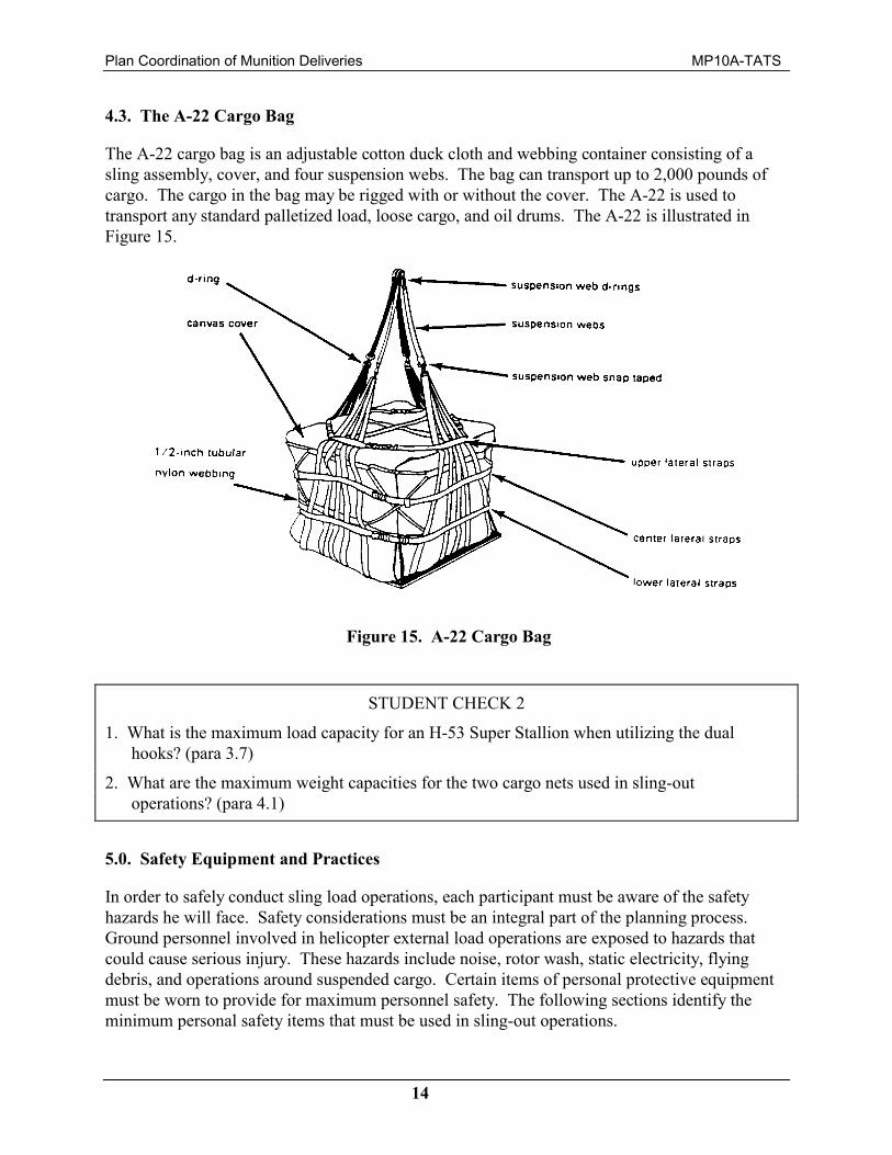
4.3. The A-22 Cargo Bag
The A-22 cargo bag is an adjustable cotton duck cloth and webbing container consisting of a sling assembly, cover, and four suspension webs. The bag can transport up to 2,000 pounds of cargo. The cargo in the bag may be rigged with or without the cover. The A-22 is used to transport any standard palletized load, loose cargo, and oil drums. The A-22 is illustrated in Figure 15.
STUDENT CHECK 2
1. What is the maximum load capacity for an H-53 Super Stallion when utilizing the dual hooks? (para 3.7)
2. What are the maximum weight capacities for the two cargo nets used in sling-out operations? (para 4.1)
5.0. Safety Equipment and Practices
In order to safely conduct sling load operations, each participant must be aware of the safety hazards he will face. Safety considerations must be an integral part of the planning process. Ground personnel involved in helicopter external load operations are exposed to hazards that could cause serious injury. These hazards include noise, rotor wash, static electricity, flying debris, and operations around suspended cargo. Certain items of personal protective equipment must be worn to provide for maximum personnel safety. The following sections identify the minimum personal safety items that must be used in sling-out operations.
Figure 15. A-22 Cargo Bag
Plan Coordination of Munition Deliveries MP10A-TATS
15
5.1. Personal Safety Equipment
5.1.1. Head and Neck Protection
A helmet or cranial protector is required to provide protection from flying debris and other objects. It also offers some protection if personnel are struck by the helicopter or cargo hook. The helmet must be securely fastened to ensure that it cannot be blown off or lifted up into the helicopter blades. Appendix I, FM 55-450 has a component listing for the MC-140 helmet.
5.1.2. Eye and Ear ProtectionA protective mask or eye goggles are required to protect ground crewmen’s eyes and allow them to see well enough to operate effectively. Hearing protection, such as ear plugs, must be used to protect ears from noise and the entry of sand or dust. The MC-140 multiple-purpose helmet provides protection against all the hazards listed above. It also includes a shroud for neck protection.
5.1.3. Hand Protection
All personnel should wear leather gloves to help protect their hands and fingers. If electrical worker’s gloves are available, all static wand persons should wear them for added protection from static discharge burns. To ensure adequate protection from static electric shock, electrical worker’s gloves must be inspected before and after each operation. They should be checked for excessive wear, fraying, holes, and tears. Torn gloves should not be worn since even a small hole leaves a person unprotected from static electric shock. Personnel can check for holes by filling gloves with water and squeezing them while holding the open end closed or by blowing air into them like a balloon. Submersion in water will indicate where there are leaks.
5.1.4. Clothing
To prevent clothing from flapping or snagging on cargo, the ground crew will roll their sleeves down and button their shirts and jackets. Military-approved combat, flight, or safety boots will be worn during external operations ashore. During shipboard external operations, shoes with rubber heels and soles are required. Personnel should remove watches, rings, and jewelry to prevent them from being caught in the sling set or load. Army personnel must wear their identification tags during a sling load operation. During a sling load operation with an H-53E, all personnel should wear body armor (flak jackets) because of the amount of debris blown by the rotor wash.
5.1.5. Flotation Equipment (Life Vest)
All personnel involved in shipboard operations or operations near water must wear flotation equipment.
Plan Coordination of Munition Deliveries MP10A-TATS
16
5.1.6. Other Equipment
The static discharge wand is used to protect the hookup man from static electric shock. Smoke grenades are used to mark the location of the landing site and/or indicate wind direction. Flashlights with wands are used to give hand-and-arm signals at night.
5.2. Static Electricity Safety Requirements
In flight, the stored static electric energy of any helicopter increases with helicopter weight, low humidity, and amount of debris blown by the rotor system (for instance, dust, sand, or snow). Extremely high static electric discharges may also occur during operation in or near thunderstorms. When the helicopter touches the ground, this charge is grounded out, but when the helicopter is in flight, it remains stored in the aircraft. A ground crewman provides a path for the charge to follow into the ground when he connects the apex fitting to the cargo hook. This charge may cause severe electrical burn or injury.
To avoid the possibility of a static electric shock, ground crewmen use discharge wands (field expedient and manufactured) to ground the cargo hook. Since these wands connect the helicopter to the ground, the static electric charge is dissipated and the hookup man does not receive a shock when he connects the apex fitting to the cargo hook.
5.3. Ground Crew Safety Considerations
While working near operating aircraft, ground crew personnel must be careful at all times because hazards under a hovering helicopter are not always apparent. Only trained crews should be used to rig loads and hook them to aircraft.
The following safety considerations are provided to minimize the chances of injury during hookup operations. They should be read, practiced, and included in the unit’s SOPs and training programs.
Avoid flying debris and foreign object damage.
Avoid cargo sling leg entanglement.
Avoid sharp objects that protrude from loads or aircraft.
Avoid top-heavy or unbalanced loads.
Always watch the aircraft and be ready to move out of the way quickly if the helicopter has an emergency.
Avoid moving and protruding parts of the aircraft such as main rotor blades, tail rotor blades, landing gear, and cargo hooks.

Plan Coordination of Munition Deliveries MP10A-TATS
17
Stay clear of swinging cargo hooks and cargo.
Avoid tripping over static discharge wand grounding cable.
Be alert for vehicles without brakes, with faulty brakes, or with brakes that are not engaged.
Take special care on slippery and wet surfaces, on pitching decks, and in high winds.
Wear all required safety equipment.
Be aware of procedures being performed; know what you are doing.
Use static discharge wands, regardless of the aircraft type.
Be aware of obstacles on the ground or deck that may cause you to fall.
Keep an eye on your fellow crew members; their safety is important.
Double check the load for proper rigging and sling attachment.
Do not participate in or allow horseplay.
Know your position in relation to the helicopter(s) at all times.
Watch movement of the aircraft and signals from the aircrew in case of an emergency. Remember, you will be under it.
Follow established emergency procedures. Be alert for signals from the signalman in case of an emergency.
Make sure brakes or chock blocks are engaged or installed as required.
Keep the area clear of loose equipment that could damage the aircraft or injure personnel.
Remain clear of the hookup area unless you are participating.
Know where the rendezvous point is in case of an emergency.
5.4. Safety Precautions for Hookup Personnel
The following safety precautions are recommended for hookup personnel:
Clear the area around the load of all objects that could be blown around by the rotor wash.
Limit the number of personnel involved in the hookup operation.
Wear protective equipment.
Plan Coordination of Munition Deliveries MP10A-TATS
18
Place the apex fitting/web ring and sling legs on top of the load (or to the side of the load) so that, during the hookup or lift-off, the legs will not become entangled on the load.
Use hand-and-arm signals to direct the helicopter. Hand-and-arm signals are depicted in Appendix B, FM 55-450-3.
Maintain adequate clearance between the hovering helicopter and ground personnel at all times.
Wear electrical worker’s gloves, as applicable, and use a static discharge wand during all hookups.
Exercise sound judgment and common sense when stationing yourself by or on a sling load to ensure that you can move clear to avoid injury if the load is accidentally dragged along by the hovering helicopter or prematurely lifted from the ground.
The most dangerous phase of the sling load operation occurs as the aircraft hovers over the load; therefore, the ground crew must clearly understand the emergency exit procedure. In planning a sling load operation, you must clearly identify the ground crew rendezvous point. The first area to identify is the aircraft emergency area, because the rendezvous point location is directly influenced by the aircraft emergency area location. The NCOIC must identify a rendezvous point where his ground crew can assemble after each hookup or in the event of an emergency. The rendezvous point should be well away from the aircraft emergency area. During an emergency, the ground crew should be as far away from the aircraft as possible. The rendezvous point is also a good location for all personnel not involved in the hookup operation. The rendezvous point should be an area that is easily identified by the ground crew (for instance, a tree, a bunker, building, vehicle, or wooded area) because they may be disorientated during an emergency. If the wind direction changes after you position the loads in the landing site, you may have to redesignate the aircraft emergency area and the rendezvous point because the aircraft approach direction may change.
Because of the possible danger involved in sling load operations, qualified medical personnel should be included in the planning process. If medical personnel are not available, you must plan for and train a member of the ground crew to perform emergency first aid. A first-aid kit should be included in the crew’s equipment.
6.0. Coordination
As plans are being finalized, the information is provided to the transporting unit. The liaison officers from the supported, aviation, and receiving units must agree that the mission is supportable prior to execution. This level of coordination generally takes place between G3/S3 operations sections and the aviation unit operations personnel.
Plan Coordination of Munition Deliveries MP10A-TATS
19
STUDENT CHECK 3
1. What are discharge wands used for? (para 5.2)
2. What is the most dangerous phase of a sling-out operation? (para 5.4)
7.0. Landing Site Selection and Preparation
The selection of a usable landing site is extremely important. Logistical and tactical considerations must be analyzed and taken into account to ensure that the landing sites are located at the best place to support the mission. The area must also be accessible to the aircraft that are going to use the site.
A landing zone (LZ) is an area used for helicopter landing operations. Aircraft may not be required to actually land but may need only to hover over a load. An LZ may include a number of landing sites with various landing points for individual helicopters. LZs may be designated by a series of code names. Landing sites and points are marked as designated by the aviation unit. The number of landing sites depends upon the mission, the terrain, the number of aircraft, and the amount of equipment to be lifted.
Landing site selection is predicated on the following factors:
Security and Concealment. Landing sites should be located in areas that allow for maximum security or protection. They should be shielded from enemy observation by wooded areas or by masked terrain. The selection of the approach and exit routes should also be based on the availability of good masking.
Convenience. Landing sites used primarily for supply or resupply should be located near storage or supply points to reduce ground movement of cargo after it has been delivered.
Size. The size of the landing site depends upon the number of landing points within it, the size of the landing points, the obstructions near or around the landing site, and the tactical dispersion required between the landing points. The minimum distance between landing points within a landing site is measured from the center of one landing point to the center of another.
The diameter of the landing point for each type of helicopter is shown in Table 1.

Plan Coordination of Munition Deliveries MP10A-TATS
20
7.1. Surface Conditions
Each landing point must be level and firm enough to keep a fully loaded aircraft’s landing gear from sinking into the ground. The ground is firm enough for size 1 and 2 helicopters if it can support a 1 1/4-ton truck. If the ground can support a 5-ton truck, size 3 through 5 helicopters can land without risk of sinking.
The entire landing point must be cleared of any loose material or debris to prevent it from being blown into the ground crew or rotor blades, or drawn into the helicopter engines. All trees, brush, stumps, or other obstacles that could damage the rotor blades or the underside of the aircraft must be cleared around the landing points. If trees must be cut, stumps in the immediate vicinity of the landing points must not exceed 10 inches in height on level ground or less on sloping round. It may be necessary to use axes, machetes, chain saws, or demolitions to clear underbrush and trees. It is not necessary to clear grass shorter than 1 foot that covers a level field unless a fire risk exits. Hard-packed sod makes the best natural landing area. Figure 16 shows the three different areas and conditions for each size landing point.
Table 1. Required Landing Point Sizes

Plan Coordination of Munition Deliveries MP10A-TATS
21
At a minimum, approaches and exit paths should meet criteria discussed in the following paragraphs. Approaches that do not meet these criteria may be acceptable, depending on the nature of the operation. However, when these criteria cannot be met, the supported or receiving unit must coordinate with the aviation unit or liaison officer.
7.2 Slope of Surface
Although helicopters can touchdown hover (one or two but not all of the wheels are placed on the ground) on any sloping ground that provides the necessary rotor clearance, landing sites should be selected that are as level as possible.
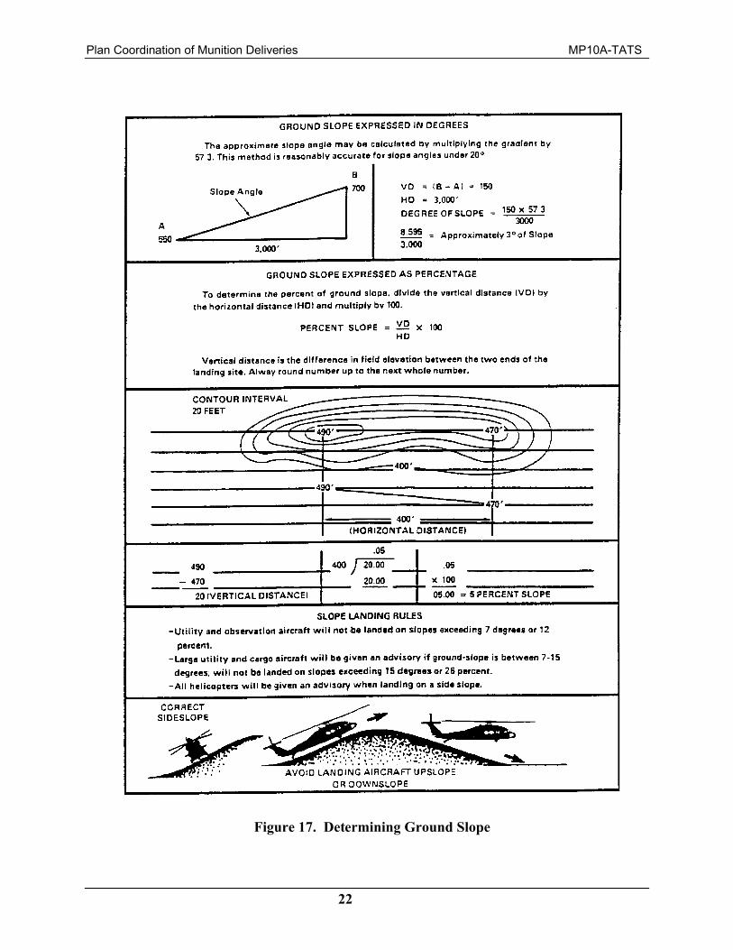
When a slope is present, it should be uniform. Figure 17 depicts how to determine ground slope.
Figure 16. Required Landing Point Characteristics
Plan Coordination of Munition Deliveries MP10A-TATS
22
Figure 17. Determining Ground Slope
Plan Coordination of Munition Deliveries MP10A-TATS
23
7.3. Wind Direction
Wind affects helicopter performance by increasing rotor lift without an increase in engine power. Therefore, less power is required to hover into the wind than to hover when no wind conditions exist; also, with constant power, a helicopter can hover into the wind with higher payloads. That is why wind condition and direction are important in the selection of landing sites and the performance of helicopters.
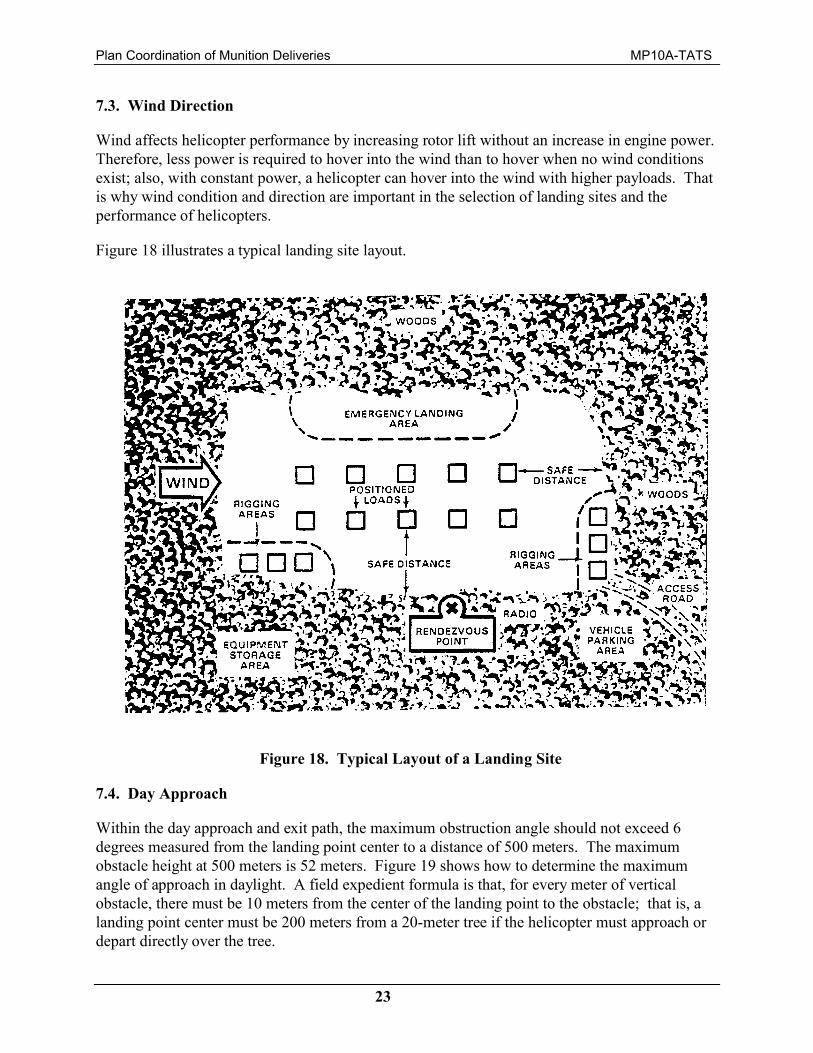
Figure 18 illustrates a typical landing site layout.
7.4. Day Approach
Within the day approach and exit path, the maximum obstruction angle should not exceed 6 degrees measured from the landing point center to a distance of 500 meters. The maximum obstacle height at 500 meters is 52 meters. Figure 19 shows how to determine the maximum angle of approach in daylight. A field expedient formula is that, for every meter of vertical obstacle, there must be 10 meters from the center of the landing point to the obstacle; that is, a landing point center must be 200 meters from a 20-meter tree if the helicopter must approach or depart directly over the tree.
Figure 18. Typical Layout of a Landing Site

Plan Coordination of Munition Deliveries MP10A-TATS
24
7.5. Night Approach
Within the night approach and exit path, the maximum obstruction angle should not exceed 4 degrees measured from the center of the landing point to a distance of 3,000 meters. Figure 20 shows how to determine the maximum angle of approach for night. The field expedient formula is that, for every meter of vertical obstacle, there must be 14 meters from the center of the landing point to the obstacle; that is, a landing point must be 280 meters from a 20-meter tree if the helicopter must approach directly over the tree.
Another night operation planning consideration is the helicopter approach and exit path area and the maximum obstacle height within that area. This criterion applies to the approach path to the landing point as well as to the exit path from the landing point. The approach and exit path is a 16-degree (277 mile) sector or arc extending outward and is measured from the center of the landing point, as shown in Figure 21.
Figure 19. Maximum Angle of Approach (Daylight)
Figure 20. Maximum Angle of Approach (Night)

Plan Coordination of Munition Deliveries MP10A-TATS
25
The V-shaped approach and exit path is depicted by the dashed and dotted line in Figure 21. The 4-degree minimum obstruction angle applies to the entire area within the approach and exit path (both the dark and light shaded area) measured from the landing point center to a distance of 3,000 meters. During night operations, as the pilot gets closer to the landing point, he needs a wider area than the 16-degree sector for a safe approach. Therefore, the minimum width of the approach and exit path, illustrated by the darker shaded areas, must be equal to or wider than the width of the landing point that must be cleared to a maximum height of 2 feet (Figure 21). The length of the minimum width area, dimension X, will vary depending on the size of the landing point. (Refer to Table 2).
The following example clarifies the night approach and exit path criteria. Table 1 identifies the UH-60 as a size 3 helicopter, and Figure 16 shows that 50 meters is the area for a size 3 landing point. Therefore, the minimum width of the night approach and exit path is 50 meters. The minimum width distance intersects the 16-degree V-shaped arc (night approach and exit path) 180 meters from the center of the landing point. Simply stated, the night maximum obstruction angle applies to the complete approach and exit path; that is, both the rectangular-shaped wedge (dark shaded area of the diagram in Figure 21) and the 16-degree V-shaped arc (light shaded area and dotted line).
Figure 21. Approach and Exit Path (Night)

Plan Coordination of Munition Deliveries MP10A-TATS
26
8.0. Landing Site Markings for Both Day and Night Uses
8.1. Daylight Markings
The landing site should be marked with marker panels or other visual means. Smoke may be used, but it also may disclose your position to the enemy. If marker panels are used alone, the wind direction is indicated by placing the crossmembers or top of the “T” into the wind. The marker panels must be securely fastened to prevent the helicopter rotor wash from tearing them from the ground. If smoke is used, it is released only after the pilot requests smoke. The pilot will then identify the color and relay it to the ground crew. The smoke canister must be far enough away from the landing point to ensure that the rotor wash does not pick up the smoke and obstruct the aircrew’s vision.
8.2. Night Markings
Landing sites and landing points used during night operations are carefully marked because the terrain features used during daytime operations are obscured. The “T” or inverted “Y” light patterns are used by Army personnel. The “T” or inverted “Y” light system is used to assist the pilot in locating, landing, and maneuvering within the site. The following factors should be considered:
Especially intense or high beams can temporarily blind the pilot. Only use dim lights in the vicinity of the landing site.
Chemlights, wands, or flashlights may be used to mark the landing sites and points.
Compatible lighting must be used when the aircrew is using night vision goggles.
Table 2. Dimension X

Plan Coordination of Munition Deliveries MP10A-TATS
27
The inverted “Y” light formation (Figure 22) is set up using four lights positioned according to Figure 22. The cargo is placed between the two stem lights and is aligned with the base and directional lights. The single aircraft or lead aircraft in a formation flight will touch down or hover into the “Y,” midway between the legs of the “Y.”
The “T” light formation is set up using five lights placed according to Figure 23. The cargo is positioned 5 meters to the left of the base light and midway between the base light and stem light. The lead aircraft lands to the left of the base light and just short of the stem lights.
Figure 22. Inverted “Y” Light Formation
Figure 23. “T” Light Formation
Plan Coordination of Munition Deliveries MP10A-TATS
28
8.3. Marking Landing Points
The inverted “Y” and “T” light formations identify the landing site. Multiple landing points must be marked within the landing site so that the pilot will know where the load is located. Landing points for size 1 through 3 helicopters are marked with a single light. Landing points for size 4 and 5 helicopters are marked with two lights spaced 10 meters apart. The aircraft lands to the left of the lights. As an additional reference point to assist the pilot, three lights may be placed in a triangular formation 25 meters upwind of the landing point. The three lights are positioned 5 meters apart from each other with two of the lights placed in a straight line with the landing point. The third light is placed to the right of the line midway between the two lights. Whenever the landing site permits, the landing points should be increased to the next larger size to provide an extra margin of safety for night operations.
8.4. Marking Obstacles
During daylight operations, obstacles that are difficult to detect or impossible to remove, such as wires, holes, stumps, and rocks, are marked with red panels or any other easily identifiable means. Use red lights to mark obstacles for detection at night. The tactical situation may not permit the marking of all obstacles in the approach or exit path. However, red lights should be used whenever possible to mark all obstacles and hazards. Pilots should be informed of all unmarked hazards and obstacles.
9.0. Training
Proper training of personnel involved in helicopter sling-out operations is essential, especially in the areas of safety and rigging. Training time must be built into the planning process to ensure that all ground personnel are proficient in every aspect of sling-out operations.
Unit commanders are responsible for training their personnel and determining the level of proficiency for those personnel in helicopter external load operations.
All personnel involved in the operation must be thoroughly familiar with the following training objectives:
Knowledge and recognition of lifting devices (for example, slings, nets, and pendants)
Knowledge of the operation and maintenance of slings and other lifting devices
Knowledge of approved rigging procedures for external loads
Familiarity with the helicopter and its cargo hook system
Knowledge of hazards and safety procedures
Familiarity with equipment in their unit that is routinely lifted by helicopter
Knowledge of ground crew tasks and responsibilities
Plan Coordination of Munition Deliveries MP10A-TATS
29
Knowledge of standard hand-and-arm signals
Knowledge of proper radio procedures and communications security
Knowledge of shipboard operations (as required).
10.0. Communications Security (Comsec)
Radio security is an important part of ground crew training. In a hostile area, the safety of both the helicopter and ground crew is at risk if the enemy determines your position. Higher headquarters issues the call signs and radio frequencies in the signal operation instructions (SOI). These call signs and frequencies are needed to communicate with the pilot without giving away the type of mission or your identity. Practice good COMSEC. When using the radio, keep the following items in mind:
Avoid long messages and unnecessary talk.
Do not use proper names (for example, CPT Smith, 34th Cavalry).
Never openly give your location or describe terrain features that could identify your location.
General COMSEC considerations should be included in unit SOPs. Specific COMSEC considerations for each mission or operation are included in either Operations or Frag orders governing that operation.
STUDENT CHECK 4
1. What three factors must be considered in selecting a landing site? (para 7.0)
2. What helicopters are size 3 helicopters, and what is the minimum diameter of their landing points? (Table 1)
3. How do you determine if the landing point is firm enough to support a size 4 helicopter? (para 7.1)
4. How does wind affect helicopter performance? (para 7.3)
5. Given it is night, determine the distance to the center of a landing point from a 25-meter high obstacle using the field expedient formula. (para 7.5)
6. How are landing sites marked during daylight? (para 8.1)
7. How are landing sites marked during hours of darkness? (para 8.2)
8. What training areas in sling-out operations require special areas of emphasis? (para 9.0)

Plan Coordination of Munition Deliveries MP10A-TATS
30
LESSON 10 STUDENT CHECK ANSWERS
Student Check 1
1. Prior planning, along with the coordination of plans with the aviation liaison officer, is essential for a smooth, safe operation.
2. The four considerations are:
The quantity and type of equipment to be externally transported. The number of aircraft available. The amount of time the unit has to relocate or resupply other units. The frequency with which the unit will transport equipment/munitions by helicopter.
3. The hook-up and receiving teams.
Student Check 2
1. 32,000 pounds.
2. 5,000 and 10,000 pounds.
Student Check 3
1. Discharge wands are used to ground the cargo hook to avoid the possibility of static electric shock.
2. The most dangerous phase occurs as the aircraft hovers over the load.
Student Check 4
1. Security and Concealment, Convenience, and Size.
2. The size “3” helicopters are the UH-60 and H-2. Minimum diameter of the landing point is 50 meters.
3. The ground is firm enough for a size “4” helicopter if it can support a 5-ton truck without sinking.
4. Wind direction affects helicopter performance by increasing rotor lift without and increase in engine power. It requires less power to hover into the wind.
5. 350 meters.
6. They are marked with marker panels or other visual means.

Plan Coordination of Munition Deliveries MP10A-TATS
31
7. They are marked with either the “T” or inverted “Y” light patterns.
8. Safety and rigging.

Plan Coordination of Munition Deliveries MP10A-TATS
32
This page intentionally left blank.