10. MANAGEMENT PLANS - Alcoa€¦ · 10. MANAGEMENT PLANS ... This document is based on drafts...
116
Environmental Review and Management Programme Wagerup Refinery Unit 3 May 2005 Alcoa World Alumina Australia Page 389 Ref: ERMP Wagerup Unit 3 May 05 ENVIRON 10. MANAGEMENT PLANS The following section contains specific management plans for the Proposal to manage the following key environmental factors: • Air Quality – refer to Section 10.1 for the Air Quality Management Plan; • Noise – refer to Section 10.2 for the Noise Management Plan; • Water Supply – refer to Section 10.3 for the Water Supply Management Plan; and • Spill Management – refer to Section 10.4 for the Spill Management Plan..
-
Upload
vuongkhanh -
Category
Documents
-
view
213 -
download
1
Transcript of 10. MANAGEMENT PLANS - Alcoa€¦ · 10. MANAGEMENT PLANS ... This document is based on drafts...

Environmental Review and Management Programme Wagerup Refinery Unit 3 May 2005 Alcoa World Alumina Australia Page 389
Ref: ERMP Wagerup Unit 3 May 05 ENVIRON
10. MANAGEMENT PLANS
The following section contains specific management plans for the Proposal to manage the following key environmental factors:
• Air Quality – refer to Section 10.1 for the Air Quality Management Plan; • Noise – refer to Section 10.2 for the Noise Management Plan; • Water Supply – refer to Section 10.3 for the Water Supply Management Plan; and • Spill Management – refer to Section 10.4 for the Spill Management Plan..
Environmental Review and Management Programme Wagerup Refinery Unit 3 May 2005 Alcoa World Alumina Australia Page 390
Ref: ERMP Wagerup Unit 3 May 05 ENVIRON
10.1 AIR QUALITY MANAGEMENT PLAN

AIR QUALITY MANAGEMENT PLAN
Wagerup Refinery Unit 3 for
Alcoa World Alumina Australia ENVIRON Australia Pty Ltd Suite 3, Level 2 200 Adelaide Terrace East Perth, Western Australia 6004 www.environcorp.com Telephone: +618 9225 5199 Ref: Air Quality Management Plan- Wagerup ERMP May 05 Facsimile: +618 9225 5155 9 May 2005

ENVIRON Telephone: +618 9225 5199 Suite 3, Level 2 Facsimile: +618 9225 5155 200 Adelaide Terrace East Perth, Western Australia 6004 www.environcorp.com
FOREWARD
This document has been prepared as part of the Wagerup Unit 3 Expansion Project, and is intended to reflect Alcoa’s public commitment to transparency in its environmental management program. Public comments and submissions on its contents may be forwarded by mail to:
Environmental Manager Wagerup Refinery South West Highway P. O. Box 84 Wagerup, Western Australia 6215
or by email to: [email protected] This document is based on drafts prepared for Alcoa by consultants Environ. It will be reviewed and amended from time to time, and a current version maintained by Wagerup Refinery operations.

Air Quality Management Plan Wagerup Refinery Unit 3 May 05 Alcoa World Alumina Australia Page iii
Ref: Air Quality Management Plan- Wagerup ERMP May 05.doc ENVIRON
TABLE OF CONTENTS
Page No.
1 INTRODUCTION......................................................................................................................... 1 1.1 BACKGROUND ...................................................................................................................... 1 1.2 PURPOSE AND SCOPE OF PLAN....................................................................................... 1 1.3 TYPES OF AIR EMISSIONS................................................................................................. 2
2 OBJECTIVES AND TARGETS.................................................................................................. 3 2.1 BACKGROUND ...................................................................................................................... 3 2.2 ENVIRONMENTAL LICENCE LIMITS............................................................................. 4 2.3 ERMP COMMITMENTS AND PUBLIC UNDERTAKINGS............................................ 4
2.3.1 Odour .............................................................................................................. 5 2.3.2 Dust ................................................................................................................. 6 2.3.3 Short-term air emission impacts................................................................... 6 2.3.4 Long-term emission impacts & health risk.................................................. 6
3 WAGERUP EMISSION SOURCES ........................................................................................... 6 3.1 BACKGROUND ...................................................................................................................... 6 3.2 MONITORING PHASES – DEFINITION OF..................................................................... 9 3.3 POINT SOURCE MANAGEMENT PLAN ........................................................................ 10
3.3.1 Oxalate Kiln ................................................................................................. 10 3.3.2 Liquor Burner .............................................................................................. 12 3.3.3 Calciners ....................................................................................................... 14 3.3.4 Power House Boilers .................................................................................... 17 3.3.5 Cooling Towers ............................................................................................ 19 3.3.6 25A Tank Vents............................................................................................ 21 3.3.7 Other Minor Sources ................................................................................... 23 3.3.8 Summary of Changes – Point Sources ....................................................... 23 3.3.9 Source Monitoring Program....................................................................... 25
3.4 RDA SOURCE MANAGEMENT PLAN ............................................................................ 25 3.4.1 Residue Drying Areas (RDA)...................................................................... 25 3.4.2 Other Major Diffuse Sources...................................................................... 26 3.4.3 Minor Sources .............................................................................................. 27 3.4.4 Summary of Changes – Diffuse Sources .................................................... 28
3.5 AMBIENT MONITORING PROGRAM ............................................................................ 28 3.5.1 Dust ............................................................................................................... 28 3.5.2 Odour ............................................................................................................ 29 3.5.3 Other Gaseous Pollutants............................................................................ 29

Air Quality Management Plan Wagerup Refinery Unit 3 May 05 Alcoa World Alumina Australia Page iv
Ref: Air Quality Management Plan- Wagerup ERMP May 05.doc ENVIRON
4 QUALITY CONTROL AND REPORTING ............................................................................ 30
5 REVIEW AND UPDATE OF MANAGEMENT PLAN.......................................................... 31
6 REPORTING OF RESULTS..................................................................................................... 31
7 REFERENCES............................................................................................................................ 32
8 GLOSSARY................................................................................................................................. 33

Air Quality Management Plan Wagerup Refinery Unit 3 May 05 Alcoa World Alumina Australia Page v
Ref: Air Quality Management Plan- Wagerup ERMP May 05.doc ENVIRON
LIST OF TABLES
Table 1: Summary of Environmental Licence Limits-Alcoa Wagerup…...............................................4
Table 2: Summary of Major and Minor Sources……………………………………………………….7
Table 3: Summary of Monitoring and Management Measures – Oxalate kiln……………………….11
Table 4: Summary of Monitoring and Management Measures – Liquor Burner……………………..13
Table 5: Summary of Monitoring and Management Measures – Calciners…………………………..15
Table 6: Summary of Monitoring and Management Measures – Boilers and Gas Turbines…………18
Table 7: Summary of Monitoring and Management Measures – Cooling Towers…………………...20
Table 8: Summary of Monitoring and Management Measures – 25A Tank Vents…………………..22
Table 9: Summary of Changes to Point Sources …………………………………………………….24
Table 10: General Quality Control Commitments……………………………………………………31
LIST OF FIGURES
Figure 1: Site Location – Wagerup Refinery
Figure 2: Process Summary – Wagerup Refinery
Figure 3: Ambient Monitor Locations – Wagerup Refinery
LIST OF APPENDICIES
Appendix A: Summary of Monitoring Programs

Air Quality Management Plan Wagerup Refinery Unit 3 May 05 Alcoa World Alumina Australia Page vi
Ref: Air Quality Management Plan- Wagerup ERMP May 05.doc ENVIRON
(This page has been left blank intentionally)

Air Quality Management Plan Wagerup Refinery Unit 3 May 05 Alcoa World Alumina Australia Page vii
Ref: Air Quality Management Plan- Wagerup ERMP May 05.doc ENVIRON
EXECUTIVE SUMMARY
The purpose of this Air Quality Management Plan (AQMP) is to document Wagerup’s existing and proposed monitoring regimes and outline management and mitigation measures proposed to reduce air emission from various key areas of the facility as a result of the Wagerup3 Project (The Project). In addition, this plan also outlines the management and monitoring commitments for point and diffuses sources on the premises, as well as subsequent ambient monitoring programs. The main identified point sources for the Wagerup refinery are associated with the major pieces of process equipment such as calciner stacks, liquor burner flue, oxalate plant stack, boiler flues and cooling towers. The main identified diffuse sources for the Wagerup refinery include areas such as the residue drying beds, cooling ponds, Superthickner and liquor storage areas. The emissions from the various point and diffuse sources for Wagerup refinery can be broadly
categorised as follows:
1. Particulate matter (e.g. total suspended particulates and various sizes of dust);
2. Volatile organic compounds (e.g. aldehydes, ketones, polyaromatic hydrocarbons (PAH’s)
and Benzene, Toluene, Ethyl Benzene and Xylene (BTEX));
3. Combustion gases (e.g. nitrogen oxides, sulphur dioxide and carbon monoxide);
4. Trace metals (e.g. nickel, cadmium and mercury)
5. Odour
These groups of substances are emitted from different stages of the alumina refining process and are not present at all source locations. Having a defined monitoring program as outlined within this AQMP creates a framework for collating data and interpreting the results. It will also assist in identifying continual improvement within Wagerup’s refinery operations. The monitoring program outlines the substances to be sampled, the frequency of the sampling program and the methodology used. The monitoring program outlined in this document has three distinct phases: commissioning monitoring; performance verification monitoring; and compliance monitoring with the intention to verify the commitments made within the Environmental Review and Management Program (ERMP). The management and mitigation measures outline the reductions estimated based on the installation of emission control equipment and other process efficiencies. This also includes ongoing management measures that will be undertaken to ensure that these reductions are sustained.

Air Quality Management Plan Wagerup Refinery Unit 3 May 05 Alcoa World Alumina Australia Page viii
Ref: Air Quality Management Plan- Wagerup ERMP May 05.doc ENVIRON
(This page has been left blank intentionally)

Air Quality Management Plan Wagerup Refinery Unit 3 May 05 For Alcoa World Alumina Australia Page 1
Ref: Air Quality Management Plan- Wagerup ERMP May 05.doc ENVIRON
AIR QUALTIY MANAGEMENT PLAN Wagerup Refinery Unit 3
for Alcoa World Alumina Australia
1 INTRODUCTION
1.1 BACKGROUND Alcoa’s Wagerup alumina refinery and its associated bauxite residue drying areas (RDAs) are located 120 kilometres south of Perth, two kilometres north of Yarloop and approximately seven kilometres south of Waroona. The refinery is located close to the foot of the Darling Scarp and is separated from the RDAs by the South West Highway and the Perth-Bunbury railway line (refer to Figure 1). The refinery produces alumina using the Bayer process from bauxite mined at the Willowdale mine site.
Alcoa proposes to expand its existing Wagerup alumina refinery through completing the construction of a third production unit. Construction of the third production unit will increase production from 2.41 million tones per annum (Mtpa) to a total of 4.7 Mtpa. An ERMP has been prepared and submitted to the Environmental Protection Authority (EPA) for assessment under Part IV of the Environmental Protection Act 1986. This AQMP forms part of the ERMP and is included as an Appendage to the document. A simplified flow diagram for the refining process is presented in Figure 2. Components of the process that are significant sources of air emissions are explained in the following sections. For a full description of the production process and the nature of the expansion Project works, refer to the document Environmental Review and Management Programme - Wagerup Refinery Unit 3, March 2005. 1.2 PURPOSE AND SCOPE OF PLAN The purpose of this AQMP is to document the air quality monitoring and management initiatives that will be used to assess any significant air quality predictions or assumptions made as part of the ERMP. This will also provide a platform for identifying areas for continual improvement at the Wagerup refinery in relation to air quality. This plan will form part of the overall Wagerup refinery environmental management system and addresses the following aspects:
1. A description of air emission sources and compounds of interest; 2. A summary of existing and proposed major sources with proposed changes and
control measures; 3. A summary of the proposed monitoring programs during plant commissioning and
operation; 4. A summary of the management and mitigation measures; and

Air Quality Management Plan Wagerup Refinery Unit 3 May 05 For Alcoa World Alumina Australia Page 2
Ref: Air Quality Management Plan- Wagerup ERMP May 05.doc ENVIRON
5. Ongoing air emission monitoring programs. The scope of this AQMP does not include greenhouse gas emissions as this will be addressed in a separate greenhouse gas management plan. 1.3 TYPES OF AIR EMISSIONS
Air emissions are usually grouped into two categories: point source emissions; and diffuse source emissions. Point source emissions arise where the vapors or particulates have been channeled or directed to a defined point prior to emission to atmosphere, such as stacks and vents. Diffuse source emissions originate over a broader area where there is little or no redirection of the vapors or particulates. Examples of diffuse source emissions include large drying beds and lake surfaces. The main identified point sources for the Wagerup refinery are associated with the major pieces of process equipment such as calciner stacks, liquor burner flue, oxalate plant stack, boiler flues, calcination vacuum pumps and cooling towers. The main identified diffuse sources for the Wagerup refinery include areas such as the residue drying beds, cooling ponds, Superthickner and liquor storage areas. The emissions from the various point and diffuse sources for Wagerup refinery can be broadly categorised as follows:
1. Particulate matter (e.g. total suspended particulates and various sizes of dust); 2. Volatile organic compounds (e.g. aldehydes, ketones, PAH’s and BTEX); 3. Combustion gases (e.g. nitrogen oxides (NOx) and carbon monoxide (CO)); 4. Trace metals (e.g. nickel, cadmium and mercury) and 5. Odour
Not all sources have the range of emissions listed above. For example bauxite stockpiles can emit metals in dust, but are unlikely to emit measurable amounts of volatile organic compounds.

Air Quality Management Plan Wagerup Refinery Unit 3 May 05 For Alcoa World Alumina Australia Page 3
Ref: Air Quality Management Plan- Wagerup ERMP May 05.doc ENVIRON
2 OBJECTIVES AND TARGETS 2.1 BACKGROUND Alcoa has adopted sustainability principles and it is a requirement that these principles be considered during all new projects. The principles are as follows:
1. Respect and protect people 2. Build community experience and well being 3. Long-term economic benefit 4. Efficient resource use and cleaner production 5. Ecological integrity and biodiversity 6. Meeting the needs of current and future generations 7. Stakeholder involvement 8. Accountability and governance
The following general air quality objectives and targets build upon Alcoa’s sustainability principles.
1. The nature and impacts of air emissions are well understood by Alcoa. 2. The nature and impacts of air emissions are well understood by external stakeholders,
and particularly the local community. 3. Air emissions do not adversely affect the health of Alcoa. 4. Air emissions do not adversely affect the health of the local community or any other
external stakeholder. 5. Air emissions do not adversely impact on the physical environment. 6. Air emissions do not unreasonably impact on public amenity. 7. Air emissions are minimised as far as reasonably practicable. 8. Plant emissions controls are operated effectively. 9. Air dispersion modeling undertaken during the environmental impact assessment
process is validated. 10. Compliance with all relevant legislation is achieved.
The above general air quality objectives and targets have been used as a basis for developing the monitoring programmes within the AQMP along with existing air quality licence limits, commitments to reduce emissions as outlined within the ERMP (ENVIRON 2005). The results obtained from within this management and monitoring program will need to comply with the various regulatory limits and demonstrate reduction commitments as outlined in the following sections.
Air Quality Management Plan Wagerup Refinery Unit 3 May 05 For Alcoa World Alumina Australia Page 4
Ref: Air Quality Management Plan- Wagerup ERMP May 05.doc ENVIRON
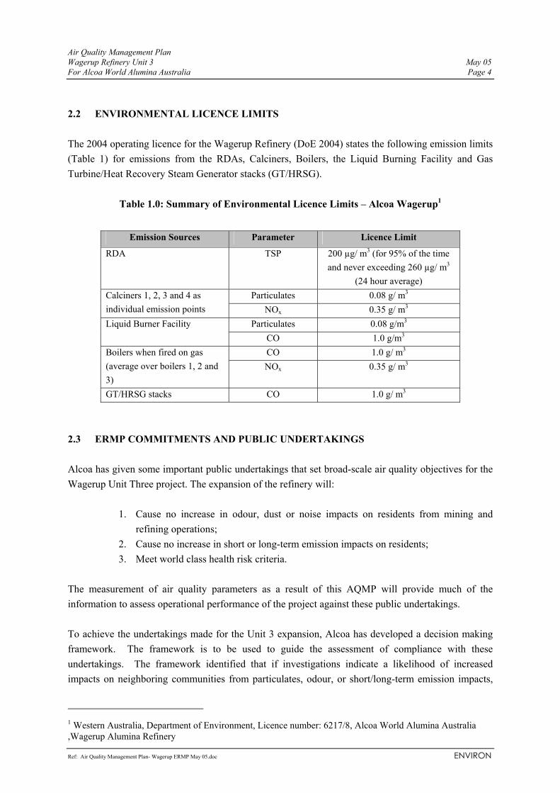
2.2 ENVIRONMENTAL LICENCE LIMITS The 2004 operating licence for the Wagerup Refinery (DoE 2004) states the following emission limits (Table 1) for emissions from the RDAs, Calciners, Boilers, the Liquid Burning Facility and Gas Turbine/Heat Recovery Steam Generator stacks (GT/HRSG).
Table 1.0: Summary of Environmental Licence Limits – Alcoa Wagerup1
Emission Sources Parameter Licence Limit
RDA TSP 200 µg/ m3 (for 95% of the time and never exceeding 260 µg/ m3
(24 hour average) Particulates 0.08 g/ m3 Calciners 1, 2, 3 and 4 as
individual emission points NOx 0.35 g/ m3 Particulates 0.08 g/m3 Liquid Burner Facility
CO 1.0 g/m3 CO 1.0 g/ m3 Boilers when fired on gas
(average over boilers 1, 2 and 3)
NOx 0.35 g/ m3
GT/HRSG stacks CO 1.0 g/ m3 2.3 ERMP COMMITMENTS AND PUBLIC UNDERTAKINGS Alcoa has given some important public undertakings that set broad-scale air quality objectives for the Wagerup Unit Three project. The expansion of the refinery will:
1. Cause no increase in odour, dust or noise impacts on residents from mining and refining operations;
2. Cause no increase in short or long-term emission impacts on residents; 3. Meet world class health risk criteria.
The measurement of air quality parameters as a result of this AQMP will provide much of the information to assess operational performance of the project against these public undertakings. To achieve the undertakings made for the Unit 3 expansion, Alcoa has developed a decision making framework. The framework is to be used to guide the assessment of compliance with these undertakings. The framework identified that if investigations indicate a likelihood of increased impacts on neighboring communities from particulates, odour, or short/long-term emission impacts,
1 Western Australia, Department of Environment, Licence number: 6217/8, Alcoa World Alumina Australia ,Wagerup Alumina Refinery

Air Quality Management Plan Wagerup Refinery Unit 3 May 05 For Alcoa World Alumina Australia Page 5
Ref: Air Quality Management Plan- Wagerup ERMP May 05.doc ENVIRON
project modifications will be necessary for the project to proceed. In the case of emissions three general options may be available to offset potential impacts, using the decision making framework:
1. Additional works to reduce emissions; 2. Increased dispersion; or 3. Increased separation between source and receptors.
Emission measurement and air dispersion modelling have been used to assess the potential for air quality impacts from implementation of the project, the results of which are detailed in the ERMP. Engineering design and operational changes, coupled with modelling have been used to manage potential increases in emissions and, where appropriate, increased emission dispersion. Furthermore, Alcoa’s land management strategy provides an ongoing offer to purchase properties in the immediate vicinity of the refinery (known as Area A) at 135% of market value. This will remain in place following commissioning of the Unit Three, if approved. This combination provides the overall framework to ensure the public undertakings in relation to the expansion can be met. To assess if Alcoa is meeting its public undertakings, specific objectives have been set for noise, dust, odour and other emissions. The objectives for each of these areas are described by the following: 2.3.1 Odour Alcoa has given an undertaking that the expansion of the refinery will:
Cause no increase in odour, dust or noise impacts on residents from mining and refining operations;
These undertakings are supported by specific objectives. In respect of odour, Alcoa’s specific objective is that the odour impacts predicted for the expansion satisfy the EPA Odour Guidance Statement Number 47 objective ‘that for expansion of existing odour sources there would be no deterioration of current amenity values’. Or in other words, that predicted odour concentrations at sensitive land uses will not increase. This will be measured as follows;
1) There will be no increase in ‘peak odour impacts’, defined as 99.9% 3 minute average odour concentrations at neighbouring residences for refinery peak emissions; and
2) There will be no increase in ‘average odour impacts’, defined as 99.5% 3 minute average odour concentrations at neighbouring residences for refinery average emissions.

Air Quality Management Plan Wagerup Refinery Unit 3 May 05 For Alcoa World Alumina Australia Page 6
Ref: Air Quality Management Plan- Wagerup ERMP May 05.doc ENVIRON
2.3.2 Dust The predicted ground-level dust concentrations, from refinery operations, meet the National Environmental Protection Measure (NEPM) 24-hour PM10 goal of 50 µg/m3 and the Kwinana EPP Area B limit for TSP of 260 µg/m3 at neighbouring residences. 2.3.3 Short-term air emission impacts The acute hazard indices, based on 1 and 24 hour values, as predicted in the health risk assessment will meet world class guidelines (that is remain < 1 at all neighbouring residences following the expansion). Also predicted short-term refinery emission concentrations (3-10 minute peak values) do not increase at neighbouring residences or if any target compound (VOCs and metals) does show an increase it remains at insignificant concentrations. There are generally not health guidelines for these time periods, however an assessment will be made relative to health guidelines that do exist. 2.3.4 Long-term emission impacts & health risk Both the chronic health index and incremental cancer risk predictions (parts of the Health Risk Assessment) meet world class guidelines: The air dispersion modelling and Health Risk Assessment undertaken as part of this ERMP have established that the predicted air quality outcomes following commissioning of the Unit Three project will satisfy each of the measures described above. This AQMP proposes additional investigations and monitoring to verify that the assumptions inherent in the model predictions are correct and that air quality measurement post-commissioning of the project confirms the above targets have been met. Through the ERMP, Alcoa has committed to minimising point and diffuse source emissions where practicable.
3 WAGERUP EMISSION SOURCES
3.1 BACKGROUND
There are a large number of point and diffuse sources at the Wagerup Refinery with approximately 37 sources identified in the expansion scenario to be the main sources contributing to atmospheric emission from the refinery. The above 37 sources includes the two powerhouse options under consideration which are the implementation of additional boilers or cogeneration. These sources are further divided into major and minor sources based on their individual contribution to overall refinery emissions and their potential to contribute to health risk i.e, major sources are those sources that are large contributors to overall refinery emissions and hazard indices.
Air Quality Management Plan Wagerup Refinery Unit 3 May 05 For Alcoa World Alumina Australia Page 7
Ref: Air Quality Management Plan- Wagerup ERMP May 05.doc ENVIRON
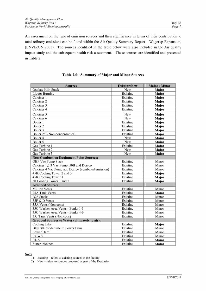
An assessment on the type of emission sources and their significance in terms of their contribution to total refinery emissions can be found within the Air Quality Summary Report – Wagerup Expansion, (ENVIRON 2005). The sources identified in the table below were also included in the Air quality impact study and the subsequent health risk assessment. These sources are identified and presented in Table 2.
Table 2.0: Summary of Major and Minor Sources
Sources Existing/New Major / MinorOxalate Kiln Stack New Major Liquor Burning Existing Major Calciner 1 Existing Major Calciner 2 Existing Major Calciner 3 Existing Major Calciner 4 Existing Major Calciner 5 New Major Calciner 6 New Major Boiler 1 Existing Major Boiler 2 Existing Major Boiler 3 Existing Major Boiler 2/3 (Non-condensables) Existing Major Boiler 4 New Major Boiler 5 New Major Gas Turbine 1 Existing Major Gas Turbine 2 New Major Gas Turbine 3 New Major Non-Combustion Equipment Point Sources: OBF Vac Pump Stack Existing Minor Calciner 1,2,3 Vac Pump, 50B and Dorrco Existing Minor Calciner 4 Vac Pump and Dorrco (combined emission) Existing Minor 45K Cooling Tower 2 and 3 Existing Major 45K Cooling Tower 1 Existing Major 50 Cooling Tower 1 and 2 Existing Major Grouped Sources: Milling Vents Existing Minor 25A Tank Vents Existing Major B26 Stacks Existing Minor 35F & D Vents Existing Minor 35A Vents (Non cons) Existing Minor 35C Washer Area Vents - Banks 1-3 Existing Minor 35C Washer Area Vents - Banks 4-6 Existing Minor 35J Tank Vents (Non cons) Existing Minor Grouped Sources to Water (ultimately to air): Cooling Lake Existing Major Bldg 30 Condensate to Lower Dam Existing Minor Lower Dam Existing Minor ROWS Existing Minor RDA Existing Major Super thickner Existing Major
Notes
1) Existing – refers to existing sources at the facility 2) New – refers to sources proposed as part of the Expansion

Air Quality Management Plan Wagerup Refinery Unit 3 May 05 For Alcoa World Alumina Australia Page 8
Ref: Air Quality Management Plan- Wagerup ERMP May 05.doc ENVIRON
The main focus of the emissions monitoring and mitigation program are on those sources identified in this report as major sources (based on their contribution to overall refinery emission and health risk). In order to increase production without increasing atmospheric emissions, the project focus was to implement emission control equipment to key components of the refinery process and to continuously improve management practices to achieve further improvements in emissions management. The significant sources included in the modeling of refinery emissions account for approximately 96% of the total mass of refinery air emissions. Sources not included in modelling together account for the remaining 4%, with no individual source among these accounting for 1% or more of air emissions. Some of these sources not included in modelling of specific substances for the HRA are included in odour modeling. This section therefore outlines the monitoring, management and mitigation measures proposed to ensure no further increase in atmospheric emissions for the major sources.

Air Quality Management Plan Wagerup Refinery Unit 3 May 05 For Alcoa World Alumina Australia Page 9
Ref: Air Quality Management Plan- Wagerup ERMP May 05.doc ENVIRON
3.2 MONITORING PHASES – DEFINITION OF
The monitoring program specifically outlines what substances are being sampled, the frequency of sampling and the methodology used. The program has three distinct phases where emissions are expected to differ due to the increasing production rates during the expansion and normal operation. Reference is made throughout this document to ‘commissioning’, ‘performance verification monitoring’, and ‘on-going monitoring’. For the purposes of this management plan, these terms have the following meanings:
• Commissioning monitoring – refers to the functional testing of continuous monitoring equipment such as temperature gauges as well as source emission monitoring. It is anticipated that direct measurements will be undertaken during the dry commissioning phase before the equipment is linked back to the process stream as well as during commissioning after the equipment is linked to the process. Commissioning monitoring is predominantly undertaken to ensure that new plant and equipment meet manufacturer specifications.
• Performance Verification Monitoring - is an intensive investigation of emissions
immediately following the commissioning of new plant and equipment associated with the Project. The objective of monitoring during this phase is to determine the nature and extent of emissions generated during the range of normal operation in the weeks and months immediately following commissioning of equipment.
• On-going Monitoring – refer to monitoring of emissions as part of Alcoa Licence
arrangements to ensure that licence limits are not exceeded and to assist with identifying further areas for improvement within the refinery. For the purposes of this AQMP, on-going monitoring for proposed new plant such as calciners and powerhouse boilers are assumed to be analogous to existing calciners and boilers. Additional on-going programs proposed are also detailed under this section.
Due to their nature, ‘performance verification monitoring’ are proposed to be more extensive than compliance monitoring, both in terms of the number of parameters monitored and the frequency of monitoring. In designing the monitoring program, consideration was also given to the point source’s contribution to the total emission for each type of substance. For example, the monitoring program for the boilers does not include particulates as their overall contribution to particulate emissions is low. A summary of the point source monitoring program during the different phases of operation can be found in Appendix A. Data gathered during the ‘performance verification monitoring’ will be used to compare emissions generated after the expansion for comparison against baseline data collected before the works commenced. The intention is that this will verify whether the commitments made by Alcoa are being met. A summary of the proposed monitoring programs that are likely to be undertaken are outlined in this AQMP with a view to formalise a comprehensive program prior to the commissioning stage.

Air Quality Management Plan Wagerup Refinery Unit 3 May 05 For Alcoa World Alumina Australia Page 10
Ref: Air Quality Management Plan- Wagerup ERMP May 05.doc ENVIRON
3.3 POINT SOURCE MANAGEMENT PLAN The following sections outline the monitoring programs and management measures to be undertaken to meet the above stipulated performance requirements in addition to meeting licence requirements. 3.3.1 Oxalate Kiln
Sodium oxalate is present as an impurity in the Bayer liquor, which reduces the efficiency and effectiveness of the alumina refining processes. Currently the oxalate is removed from the process and is deposited in dedicated lined areas independent of other the residue drying areas. As part of the expansion, the oxalate that is removed from the production stream will be combusted in the rotary kiln with the combusted gases directed via a wet scrubber to a RTO (regenerative thermal oxidizer) to reduce VOC and CO emissions from the discharge stack. These works are scheduled to be commissioned in 2006. Since the efficiency of the RTO is intrinsically linked to the temperature at which they operate, continuous temperature monitors will be installed. Continuous CO monitors will also be installed at the inlet and outlet of the RTO to demonstrate destruction efficiency. It is envisaged that operational and maintenance requirements of the proposed oxalate kiln and associated control equipment will follow both manufacturer’s specification and experience gained at Pinjarra. This will include targeted maintenance periods for the RTO and scrubber with control equipment linked to the process to ensure there are not uncontrolled releases of air emissions from the oxalate stack. The oxalate kiln stack is a relatively low contributor to total emissions of CO, VOC and particulates when treated, however reduction of these substances from the oxalate kiln stack will assist in meeting performance requirements. Emissions data for the Oxalate stack for Wagerup is based on the output from the Pinjarra Refinery oxalate stack, factored for production rate with an assumed 95% odour and VOC removal efficiency. This is based on operating experience gained by Worsley Alumina with a RTO unit fitted to their liquor burner demonstrating removal efficiency greater than 99%. Experience from other installations of similar RTO technology indicates that if CO is being destroyed, then VOCs will be destroyed to a similar or greater degree. Alcoa therefore intends to use continuous CO monitoring to provide a surrogate indication of ongoing VOC destruction. Presented in Table 3 are the proposed monitoring and management plans for the oxalate kiln.

Air Quality Management Plan Wagerup Refinery Unit 3 May 05 For Alcoa World Alumina Australia Page 11
Ref: Air Quality Management Plan- Wagerup ERMP May 05.doc ENVIRON
Table 3.0: Summary of Monitoring and Management Measures – Oxalate kiln
Commissioning Monitoring Performance Verification Monitoring On-going Monitoring Management Measures
Commissioning monitoring will include functional testing of the temperature control and calibration of temperature meters prior to operation of the RTO. This will include verification that the continuous CO monitors are reading correctly. In addition monitoring will be undertaken to ensure that the oxalate kiln and the associated emission control equipment meets manufacturer and performance specifications during the commissioning phase.
Monitoring during performance verification of the oxalate kiln will aim to verify the performance targets and will comprise the following elements: A planned monitoring program for particulate and trace metals will be undertaken in the weeks and months subsequent to kiln commissioning. In addition VOC monitoring will be undertaken to establish RTO destruction efficiencies. The VOCs will be sampled primarily for aldehydes and ketones as they contribute the largest proportion of total VOCs present. Interim monitoring in the first year of commissioning will be undertaken to assess the performance of the new Oxalate kiln stack and the RTO in destroying VOCs and reducing particulates. This will include regular VOC monitoring at the inlet and outlet of the RTO to verify destruction efficiencies established during commissioning and performance verification monitoring.
It is envisaged that on-going monitoring will include quarterly monitoring for particulates, with biannual monitoring for VOCs and annual monitoring for trace metals The limits for ongoing compliance monitoring will be outlined in the new licence.
The key measure to reduce emissions in the proposed oxalate kiln is the installation of an RTO to the oxalate kiln stack. Additional measures to ensure emissions management include: 1. The CO concentration will be continuously
monitored at points before and after the RTO. 2. The RTO will be shut down for planned
inspection, maintenance and overhaul to ensure effective operation.
3. Oxalate kiln stack exit gases will be monitored in accordance with the performance verification and ongoing monitoring programs
4. Alcoa will prepare and publish an interim commissioning report to verify performance of the oxalate kiln emission control equipment against regulatory design criteria.
5. Alcoa will report particulate emission monitoring results against the regulatory limit in its monitoring reports to the Department of Environment
6. Alcoa will provide statistical information regarding CO destruction efficiency in its monitoring reports to the Department of Environment.
7. Procedures will be developed to ensure that excursions in operating temperature are flagged and acted upon as quickly as possible.
8. A service contract will be maintained to ensure that repairs to the RTO unit will be undertaken as quickly as possible without compromising the quality of repairs

Air Quality Management Plan Wagerup Refinery Unit 3 May 05 For Alcoa World Alumina Australia Page 12
Ref: Air Quality Management Plan- Wagerup ERMP May 05.doc ENVIRON
3.3.2 Liquor Burner The liquor burner controls the build-up of organic compounds in the recirculating process liquor. These compounds originate from organic material in bauxite. They inhibit and eventually significantly reduce the extraction of alumina from the liquor. The liquor burner thus represents a means of ensuring the continued responsible use of the bauxite resource and minimisation of energy wastage and greenhouse gas emissions. The drying and combustion of organic components in the liquor creates a range of organic compounds, which are controlled by a range of emission control technologies including replacement of the catalytic thermal oxidiser (CTO) with an RTO and incorporating with the existing electrostatic precipitator (ESP) and dehumidifier. The RTO will be installed downstream of the ESP and the dehumidifier to ensure particulates are removed from the gas stream prior to entering the dehumidifier. There are no additional improvements planned.

Air Quality Management Plan Wagerup Refinery Unit 3 May 05 For Alcoa World Alumina Australia Page 13
Ref: Air Quality Management Plan- Wagerup ERMP May 05.doc ENVIRON
Table 4.0: Summary of Monitoring and Management Measures – Liquor Burner
Commissioning Monitoring Performance Verification Monitoring On-going Monitoring Management Measures
Commissioning monitoring will be similar to that of the oxalate kiln and will include functional testing of the temperature control and calibration of temperature meters prior to operation of the RTO. This will include verification that the continuous CO monitors are reading correctly. In addition, monitoring will be undertaken to ensure that the Liquor Burner and the associated emission control equipment meets manufacturer and performance specifications during the commissioning phase.
Monitoring during performance verification of the upgraded Liquor Burner will aim to verify the performance targets and will comprise the following elements: A comprehensive monitoring program will be undertaken to establish the destruction efficiencies of the proposed RTO. The VOCs will be sampled primarily for aldehydes and ketones as they contribute the largest proportion of total VOCs present.
Ongoing monitoring will be undertaken in accordance with program stipulated in the Wagerup Licence and will include quarterly monitoring for particulate matter and CO, NOx, SOx, acetaldehyde, acetone, 2-butanone, formaldehyde, benzene, odour concentration, temperature, stack velocity, stack flowrate and will include daily monitoring of dryer feed rate, kiln pressure and RTO pressure drop and temperatures.
The major management measure to further reduce air emission is the replacement of the CTO with an RTO to further control VOC emissions. Additional management measures will also include: 1) The CO concentration will be continuously
monitored at points before and after the RTO. 2) The RTO will be shut down for planned
inspection, maintenance and overhaul to ensure effective operation.
3) The stack exit gases will be monitored in accordance with the performance verification and ongoing monitoring programs
4) Alcoa will prepare and publish an interim commissioning report to verify performance of the Liquor Burner emissoin control equipment against regulatory design criteria.
5) Alcoa will report particulate emission monitoring results against the regulatory limit in its monitoring reports to the Department of Environment
6) Alcoa will provide statistical information regarding CO destruction efficiency in its monitoring reports to the Department of Environment.
Procedures will be developed to ensure that excursions in operating temperature are flagged and acted upon as quickly as possible.

Air Quality Management Plan Wagerup Refinery Unit 3 May 05 For Alcoa World Alumina Australia Page 14
Ref: Air Quality Management Plan- Wagerup ERMP May 05.doc ENVIRON
3.3.3 Calciners Calcination is the processing step of converting hydrated alumina to alumina. This is done by heating in a fluidised bed furnace at approximately 1000oC to drive off the water of crystallisation. There are currently four calciners (1-4) at the refinery, with two more calciners proposed to be installed during the expansion works. Calciner emissions include alumina dust, combustion products, VOCs and some trace metals. The dust emissions are controlled by electrostatic precipitators (ESP) with approximately 80% of dust emissions from the refinery process likely to be generated from the calciners (this statistic excludes dust generated from the residue area and the bauxite storage area). Calciners 5 & 6 are to be fitted with three zone ESP’s with the expected dust output limited to 10 mg/m3. The existing ESP’s on the current calciners are 2 zone, thus peak emissions when rapping will be significantly reduced on the new calciners. Calciners 3 and 4 will have an increase in their operating rate of between 20% and 40% during the expansion with Calciners 1 & 2 increasing by between 1% and 6%. Calciner 3 will be improved to match Mark VI standard to achieve similar emission levels as Calciner 4. A summary of the monitoring programs and management measures are presented in Table 5.0.

Air Quality Management Plan Wagerup Refinery Unit 3 May 05 For Alcoa World Alumina Australia Page 15
Ref: Air Quality Management Plan- Wagerup ERMP May 05.doc ENVIRON
Table 5.0: Summary of Monitoring and Management Measures – Calciners
Commissioning Monitoring Performance Verification Monitoring On-going Monitoring Management Measures
During commissioning, functional testing and calibration of the dust control monitors (DCMs) will be undertaken for Calciners 5 & 6 with comparison against isokinetic particulate matter results. The monitoring work is undertaken to confirm that the equipment is working to design specifications and to determine if particulate emissions during operation will achieve their nominated design criterion.
Performance verification monitoring will only be undertaken for Calciners 3, 5 & 6 and will aim to verify their performance targets. Sampling will be undertaken to obtain a statistically sound data set by which to verify the performance. Based on the outcomes of the performance verification monitoring, interim monitoring may be conducted for the first year. This will be dependent on the results of the commissioning and performance monitoring of Calciners 5 and 6.
On-going monitoring will be undertaken in accordance with the monitoring program stipulated in the Wagerup Licence. It is envisaged that this program will extend to the additional two calciners. The monitoring program involves 2-monthly monitoring of exit gases from all calciners for particulates, combustion products, odour, acetaldehyde, acetone, 2-butanone formaldehyde and benzene with measurements of daily gas flowrates and calciner furnace temperatures.
The measures include the management and maintenance of the emissoin control equipment installed on the calciners. The key mitigation measure is the installation of 3 zone ESP’s on the new calciners. Additional measures include: 1) The maintenance of continuous DCM’s on all
calciners. 2) Calciner 3 will be upgraded to be equivalent to
Mark VI standard to match emission characteristics of Calciner 4.
3) Calciners 5 and 6 will be installed with three zone ESP’s with the expected output limited to 10 mg/m3.
4) The modification of Calciners (1-3) such that the low volume vent emissions from each calciner are directed into the feed air into the back end of the calciner.
5) The operation of continuous dust monitors will be maintained for each calciner.
6) The calciners will be operated assuming a compliance limit of 80 mg/m3 for each calciner with an internal operating target of 60 mg/m3.
7) Planned regular maintenance will be undertaken on the ESPs for each calciner.
8) Calciner stack exit gases will be monitored in accordance with performance verification and compliance specifications.
9) A commissioning report will be prepared to verify performance of the calciner emission control systems against regulatory and internal targets. Sustained dust emissions above the target levels will be acted upon immediately in accordance with current procedures.

Air Quality Management Plan Wagerup Refinery Unit 3 May 05 For Alcoa World Alumina Australia Page 16
Ref: Air Quality Management Plan- Wagerup ERMP May 05.doc ENVIRON
Commissioning Monitoring Performance Verification Monitoring On-going Monitoring Management Measures
10) In the event of emission control equipment failure or trips, existing control procedures will be followed to mitigate the problem.

Air Quality Management Plan Wagerup Refinery Unit 3 May 05 For Alcoa World Alumina Australia Page 17
Ref: Air Quality Management Plan- Wagerup ERMP May 05.doc ENVIRON
3.3.4 Power House Boilers The boilers at Wagerup generate process steam and electricity for the refining process by means of natural gas fired boilers (Boilers 1-3) and turbo-alternators. In addition, a Gas Turbine / Heat Recovery Steam Generator is also installed for the same purpose. There are currently three boilers (three large ICAL boilers) on site with an additional two boilers proposed as one of the options for the Wagerup 3 Expansion (Boilers 4 & 5) with the other option being an additional two cogeneration units (Gas turbines and Heat Recovery Steam Generators). The existing boilers are fitted with low NOx burners with proposed boilers/GT’s also including low NOx burners. The most significant emission is NOx, with other combustion products making up the remainder of the emission from the Boilers.

Air Quality Management Plan Wagerup Refinery Unit 3 May 05 For Alcoa World Alumina Australia Page 18
Ref: Air Quality Management Plan- Wagerup ERMP May 05.doc ENVIRON
Table 6.0: Summary of Monitoring and Management measures – Boilers & Gas Turbines
Commissioning Monitoring Performance Verification Monitoring On-going Monitoring Management Measures
During commissioning of Boilers 4 and 5, monitoring will be undertaken to confirm that the equipment is working to design specifications and to determine if NOx emissions during operation will be within design specifications. Monitoring will be conducted for NOx, CO and SO2 during the initial commissioning period.
Performance verification monitoring will be undertaken to confirm that NOx emissions meet design specifications Monitoring will also be undertaken for other combustion products immediately after the boilers or the gas turbines are commissioned.
The on-going monitoring program for the existing and proposed boilers and gas turbines will closely the current licence monitoring regime. This monitoring program includes three monthly sampling for NO, NO2, NOx, CO, fuel feed rates and steam outputs over the duration of the tests. In the event that boilers 2 and 3 are fired using diesel, then the number of tests undertaken should be adequate to define the relationship between mass rates for NO and NO2 and steam output over the range of ambient temperatures that may be reasonably be expected to occur over the course of one year.
The management and mitigation measures for the boilers and gas turbines are summarised below. 1. The burners will be shut down on a regular
basis for inspection, planned maintenance and overhaul to ensure effective operation.
2. Boiler and gas turbine exit gases will be
monitored in accordance with the performance verification and ongoing monitoring programs (Appendix A).
3. Sustained emissions above the target levels
will be acted upon immediately in accordance with current procedures.

Air Quality Management Plan Wagerup Refinery Unit 3 May 05 For Alcoa World Alumina Australia Page 19
Ref: Air Quality Management Plan- Wagerup ERMP May 05.doc ENVIRON
3.3.5 Cooling Towers
Various parts of the Bayer process require the progressive cooling of hot liquor. Separate cooling water circuits are used to generate cool water. Water that has been used to cool the hot liquor is directed to the cooling towers where it is cooled so it can be recycled. There are a number of cooling towers present at the refinery, the most significant of which are the 45K1, 45K2, 45K3 50C1 and 50C2 cooling towers. These cooling towers have been identified as a source of VOC emissions from the refinery, largely due to the volume of air discharged from it. The water used in the tower is sourced from the Lower Dam and contains some VOCs in solution. Due to its size and shape, and the moisture content of the gas stream, it is difficult to accurately measure the amount of emissions discharged from the Cooling Towers. All new cooling requirements in precipitation are to be met with fin fan coolers or technology that results in similar reductions in emissions to air. Enough excess capacity is to be installed to allow for the shutdown of the 45K1 cooling tower. In addition the operation of cooling towers will be modified to achieve a 50% reduction in odorous emissions. .

Air Quality Management Plan Wagerup Refinery Unit 3 May 05 For Alcoa World Alumina Australia Page 20
Ref: Air Quality Management Plan- Wagerup ERMP May 05.doc ENVIRON
Table 7.0: Summary of Monitoring and Management Measures – Cooling Towers
Commissioning Monitoring Performance Verification Monitoring On-going Monitoring Management Measures
There is no commissioning monitoring proposed at this stage.
There is no performance monitoring proposed at this stage.
The existing cooling towers are not licenced sources and therefore do not require compliance monitoring. There is no on-going monitoring proposed at this stage
The management measures proposed for the cooling towers include: 1. All new cooling requirements in precipitation
to be met with fin fan coolers or technology that can meet similar emission reduction.
2. A 50% reduction in odorous emissions will be achieved by modifying the operation of cooling towers.

Air Quality Management Plan Wagerup Refinery Unit 3 May 05 For Alcoa World Alumina Australia Page 21
Ref: Air Quality Management Plan- Wagerup ERMP May 05.doc ENVIRON
3.3.6 25A Tank Vents Slurry storage represents the next processing step after milling and receives milled slurry to remove dissolved silica from the milled ore. It is performed at a lower temperature but has longer residence time than the subsequent digestion process. It utilises excess flash vapour from the digestion process for heating of the slurry. As a consequence there has been intermittent release of vapour from vents associated with each slurry storage tank. The slurry storage tank includes four tanks in series. The first tank is the hottest, and the only tank receiving digestion vapour directly. This is therefore considered to be the most significant source of VOCs. Additional 25A tanks are to be installed with the upgrade. Also existing contact heaters to be replaced by sealed units. This expected to reduce vapour flows from this source by 75%. No decrease in the concentration of emission from the source is expected.

Air Quality Management Plan Wagerup Refinery Unit 3 May 05 For Alcoa World Alumina Australia Page 22
Ref: Air Quality Management Plan- Wagerup ERMP May 05.doc ENVIRON
Table 8.0: Summary of Monitoring and Management Measures – 25A TANK VENTS
Commissioning Monitoring Performance Verification Monitoring On-going Monitoring Management Measures
Monitoring of the two additional tank vents will be undertaken to quantify the emissions from this source during the commissioning stage. Monitoring will focus on VOC emissions.
Performance verification monitoring will be undertaken to confirm the commissioning monitoring results.
The tank vents are not licenced sources and therefore do not require compliance monitoring. There is no on-going monitoring proposed at this stage
The major management measure for the 25A tank vents is the use of sealed units. This is expected to reduce vapour flows from this source by 75% which will have a direct reduction in mass emission rates.

Air Quality Management Plan Wagerup Refinery Unit 3 May 05 For Alcoa World Alumina Australia Page 23
Ref: Air Quality Management Plan- Wagerup ERMP May 05.doc ENVIRON
3.3.7 Other Minor Sources Minor point sources such as small vents and vacuum pumps were identified within the baseline emissions study as primarily emitting VOCs. Individually the majority of these sources contribute between less than 1% and 5% of the total refinery VOC emissions. However, when considered collectively the following emissions sources can contribute to a more significant proportion of emissions. These minor sources are:
1. Milling vents; 2. 35 F&D vents; 3. 35 A vents; 4. Liquor tank vents (35L & 35 H); 5. 35C Washer vents; 6. OBF vacuum pump stack; 7. 44 seed filtration;
Due to their number, size and nature, there are practical difficulties in obtaining samples from all of these minor emission sources, and VOC emission information is estimated. For those minor sources where there are multiple pieces of equipment of the same configuration, monitoring of a subset of sources will be used to estimate emissions from that group. For example, Alcoa may monitor emissions from a single milling vent, and assume similar emissions data for all milling vents. In order to ensure that comparisons can be made between each inventory, all sampling locations and methods utilised will be based on that documented within the Air Quality Summary Report, 2005. Any variations to this will be recorded, and where possible, reproduced in subsequent inventories. 3.3.8 Summary of Changes – Point Sources A number of sources within the expansion scenario have emission reductions (either volumetric flow rates or concentrations, or both). The mass emission rates for point sources for the base and expansion scenarios are presented in the Air Quality Summary Report (AQSR) (ENVIRON 2005). The basis of these changes reflects specific design measures and improvements in operational performance that are expected to be achieved following the refinery expansion. The basis for these design and operational improvements in reducing emissions, or in limiting their increase with the expansion is given in Table 9 for each source where a reduction or reduced increase in emissions is claimed.

Air Quality Management Plan Wagerup Refinery Unit 3 May 05 For Alcoa World Alumina Australia Page 24
Ref: Air Quality Management Plan- Wagerup ERMP May 05.doc ENVIRON
Table 9.0: Summary of Changes to Point Sources
Source Management Measure Calciner 3 1. Improvements to equivalent of Mark VI Standard Calcination 1. Peak Wagerup 3 calcination dropped to 14,400 tpd to 14,016 tpd Boilers 4 & 5 1. New boilers 4 and 5 to have low NOx burners. Calciners (1-3) Low volume vent emissions
1. The existing calciners will be modified such that the low volume emissions form each calciner are directed into the calciner combustion air.
Calciners 4-6 low volume vent emissions
1. Calciner 4 to be modified to feed existing stack emissions into calciner combustion air feed system.
2. Calciner 5 and 6 to incorporate low volume emission into combustion air feed system
Cooling Towers 1. Operation of cooling towers to be modified to achieve a 50% reduction in odorous emissions, which will also include filtration of cooling water to reduce suspended particulate matter, reduced water treatment chemical usage and alternative water source.
Milling Vents 1. The installation additional milling capacity is expected to increase vapour emissions to 133% of current flow
25A Tank Vents 1. Additional tanks to be installed with the upgrade 2. Existing tank contact heaters ot be replaced by sealed units.. 3. A reduction in vapor flows by 75% with no decrease in concentration
expected. Digestion Blow-off Containment Tank Vents
1. Unit 3 to be constructed with a spare flash tank for use during flash tank outages.
2. Improved heat recovery through better management and maintenance activities
3. Vapour emissions to be reduced to approximately 0.75tph per unit, improving the collection of vapour emissions and routing to boilers for thermal destruction.
4. 73% reduction in flowrates expected Sand Removal 1. Emissions from proposed new cyclone separation system estimated to
be approximately 50% of current emission levels Causticisation (35J) 2. 35J causticisation will be either replaced with high efficiency
causticisation units or technology installed to achieve similar emission to air output .
Clarification Filtrate (35A) 1. New filters to be modern day equivalent. No press air used to dump these filters which should avoid increasing flows from 35A vent.
2. Existing tank vents to be modified to control flow rate from the tanks. Data gathered during the commissioning and performance verification monitoring phase will be used to compare emissions generated after Wagerup 3 against baseline data (2.41 Mtpa production scenario). The intention is that this will verify whether the commitments made within the ERMP are met. The predicted expansion emissions were estimated from the baseline data that was collated. It was also adjusted to consider peak and average flows resulting from production. It was from this data that Alcoa was able to determine its emission reduction commitments summarised within the ERMP. The calculated mass emission rates for the existing and expanded scenarios are presented in the Air Quality Summary report (ENVIRON, 2005).
Air Quality Management Plan Wagerup Refinery Unit 3 May 05 For Alcoa World Alumina Australia Page 25
Ref: Air Quality Management Plan- Wagerup ERMP May 05.doc ENVIRON
3.3.9 Source Monitoring Program
Alcoa conducts air emission source monitoring at the Wagerup Refinery on a routine basis. Some of this monitoring is required to be conducted as specified in the environmental licence for the Wagerup refinery, whilst other monitoring programs have been developed to assist Alcoa with air quality management and continuous improvement. Alcoa currently has a comprehensive source emission monitoring program for the refinery which will extend to the expanded refinery scenario. A summary of the monitoring programs proposed are presented in Appendix A. In addition, where applicable campaign monitoring will be conducted for total VOCs, aldehydes and ketones to improve understanding of key emission sources. 3.4 RDA SOURCE MANAGEMENT PLAN
3.4.1 Residue Drying Areas (RDA) After digestion of alumina from the bauxite, the remaining residue slurry is washed and separated into mud and sand fractions. These are then pumped to the residue drying areas where the mud is thickened before being disposed onto drying bays. Due to the relatively low grade of Darling Range bauxite, residue is produced at a rate of approximately two dry tonnes per tonne of alumina produced. The RDA facilities at Wagerup are located on the western side of the South Western Highway. The existing RDA covers approximately 546 hectares (ha) of which approximately 170 ha are used for active drying of the residue (RDA1-7), 12 ha for the thickener bypass, 69 ha for alkaline water storage and 32 ha for fresh water storage. The RDAs are presently managed through the approved 30 year Long Term Management Residue Strategy (LTRMS). The LTRMS is prepared through consultation with the local community, local government and the Residue Planning Liaison Group (RPLG). The RPLG comprises representatives of government agencies and is chaired by the Department of Industry and Resources (DoIR). A major review of the LTRMS is planned to commence in 2005 in preparation for submission to the Minister for the Environment in 2006. The expansion of the Wagerup refinery will result in increased production of residue and will therefore require the construction of cells currently approved in the LTRMS to be brought forward. Expansion of the RDA within the 30 year plan is an ongoing process with construction work on RDA7 completed during the 2004/5 summer period and construction of RDA8 and a new fresh water detention pond planned for the 2005/6 summer period. The existing approved RDA is shown in Figure 1.

Air Quality Management Plan Wagerup Refinery Unit 3 May 05 For Alcoa World Alumina Australia Page 26
Ref: Air Quality Management Plan- Wagerup ERMP May 05.doc ENVIRON
A summary of the changes to the RDAs during the expansion include.
1. An increase in the Bauxite Residue Storage rate; 2. An expansion of the existing drying area by 80 to 100 Ha; and 3. The construction of residue drying cells approved in the LTRMS will need to be brought
forward. RDA cells 9, 10 and 11 are planned to be constructed by the year 2012 should the expansion be approved.
3.4.1.1 Management and Mitigation Measures Dust emission from the RDA’s has been recognised as a potentially significant issue and is controlled by wetting the surface of the RDA’s using sprinklers. A network of sprinklers has been installed across the drying beds and is used to dampen dry surfaces prior to and during windy periods. Other areas within the residue operations have more permanent dust suppressants applied to them, including bitumen spray, rock aggregate spread as a mulch, waste oil used as a binder on internally draining limestone roads, and grasses grown on residue sand areas which are not going to be disturbed for several years. Evaluation of the existing sprinkler patterns by Alcoa have indicated that a triangular grid pattern will improve coverage efficiency and therefore as part of the expansion, Alcoa are replacing the majority of sprinklers with a 60m x 60m triangular grid pattern. Please refer to RDA Sprinkler Deposition Modeling Report (ENVIRON 2005) for further information. In addition, other management measures adopted to further reduce dust emissions include;
1. Electrical maintenance of the sprinkler system 2. Blue metal on long term stockpiles 3. Daily dust risk rating procedure 4. Improved response to mechanical maintenance issues 5. 24hr operational coverage
The Wagerup residue operations are now accredited to ISO 14001. This has led to an increased emphasis being placed on the management of a number of activities related to dust control including timing of residue sand construction activities. 3.4.2 Other Major Diffuse Sources 3.4.2.1 Cooling lake The Cooling Lake receives a combination of high conductivity storm water run-off from the refinery site together with hot process liquor reporting to the stormwater system. Additionally excess leachate collected from the under drainage systems of the RDA’s is also directed to the Cooling Lake. Although the refinery stormwater run-off can report to both the cooling lake and the ROWS (run-off water storage) pond, it more commonly reports to the Cooling Lake. This lake generally

Air Quality Management Plan Wagerup Refinery Unit 3 May 05 For Alcoa World Alumina Australia Page 27
Ref: Air Quality Management Plan- Wagerup ERMP May 05.doc ENVIRON
contains the highest level of process liquor present at the Residue Area. The predominant air emissions from the cooling lake are VOCs carbonyl compounds and odour. The proposed monitoring program and management measures for the Cooling Lake will include:
1. Additional campaign flux chamber monitoring to confirm VOC, carbonyl and odour emission rates measured in 2004/2005;
2. Verification monitoring using upwind and downwind ambient monitoring data to confirm flux results.
3.4.2.2 Super Thickener. The fine tailing are pumped to the thickener vessel where they are settled using flocculent, producing high density underflow slurry or around 50% weight for weight solids. The slurry is then pumped to one of a number of beds where it is placed in layers up to 0.5m deep. The predominant emissions from the super thickener are VOCs, carbonyl compounds and odour. The proposed monitoring program and management measures for the Super Thickener will include:
1. Additional flux chamber monitoring of VOCs, carbonyls and odour to confirm the 2004/2005 measured emission rates.
3.4.3 Minor Sources Minor diffuse sources such as smaller water bodies and those containing lower alkalinity waters were identified within the baseline emissions study as primarily emitting VOCs. Individually the majority of these sources are minor contributors to overall emissions, and although included in the modelling are considered minor sources. These sources include:
1. Lower Dam 2. ROWS (Run Off Water Storage) 3. Oxalate Pond 4. ROCP2 5. Sand Lake
Implicit in the calculation of emission rates for the expansion is a reduction in the rate of emissions from some diffuse sources. These reductions and their basis are detailed here.

Air Quality Management Plan Wagerup Refinery Unit 3 May 05 For Alcoa World Alumina Australia Page 28
Ref: Air Quality Management Plan- Wagerup ERMP May 05.doc ENVIRON
3.4.4 Summary of Changes – Diffuse Sources A summary of the mass emissions changes for the diffusive sources as part of the expansion are outlined below.
1. Super thickener VOCs will increase by 20% of the equivalent VOC load of the Lower Dam; 2. Cooling Pond VOCs will increase by 50% of the current VOC load; 3. ROWS Pond VOCs will increase by 100% of the current VOC load; 4. ROCP no change; 5. Oxalate Pond no change; 6. RDA areas will accept 80% of the load diverted from Lower Dam, distributed across all
active surfaces; 7. Lower Dam no change; 8. Sand Lake - increase wet sand area 50% for expected 3 times increase in sand.
3.5 AMBIENT MONITORING PROGRAM
Wagerup has an extensive ambient air monitoring programme in place. The programme has a number of dimensions, which are managed and developed in a variety of ways to satisfy the various needs and stakeholders. The core of the programme is covered in the requirements of the environmental licence, which specifies targets and limits for key parameters. It is envisaged that the ongoing ambient monitoring progam will be an extension of the existing progam with a range of voluntary and joint projects also proposed to continually improve and verify the ambient air data set. The current summary does not attempt to cover in detail all of the various historical and current programs related to ambient monitoring. Rather it is a summary of the future direction with the view to demonstrate primary adherence to commitments made in the ERMP. 3.5.1 Dust 3.5.1.1 On-going Monitoring
Ambient dust monitoring at the Residue Drying Area (RDA) was the first ambient monitoring to be incorporated in Wagerup’s environmental licence. The program includes both continuous monitors such as tapered element oscillating microbalance TEOMs (Tapered Element Oscillating Microbalance) and high volume samples deployed at specific locations around the Wagerup facility. The locations of the dust monitors are shown in Figure 3, extracted from the Wagerup Annual Report 2003. The locations have been chosen to provide information for all the main wind directions, and the sites are in conformance with AS 2922-1987. Results of the monitoring are given in the Annual and Triennial Reviews. It is envisaged that the current program will be maintained through during the Wagerup 3 expansion. The program includes chemical analysis of a proportion of the samples for source identification. There is the possibility to rationalise the overall deployment of sampling stations based on information obtained.

Air Quality Management Plan Wagerup Refinery Unit 3 May 05 For Alcoa World Alumina Australia Page 29
Ref: Air Quality Management Plan- Wagerup ERMP May 05.doc ENVIRON
The locations for any additional monitors for the expansion will be chosen to provide information for all the main wind directions to ensure that the chosen sites are in conformance with AS 2922-1987. Any proposed monitoring program will include the use of TEOMS or High Volume Samplers that meet AS 3580.9.3 2003 standards. 3.5.1.2 Other Programs RDA Dust Emission Intensive Study: To better understand the composition and variability of dust generated at the RDAs, Alcoa is conducting a WA-wide study of dust characteristics, with the Pinjarra refinery as the main study site. The 15 month study commenced in Q4 2004 and has been scoped in consultation with independent consultants. Details of this program were provided to the Wagerup Tripartite Group in November 2004. The results of this program will be reviewed as it progresses to determine the need for any further site specific testing at Wagerup. In addition a PM10 monitoring program has been implemented at the Wagerup RDA to collect further information about the PM10 component of Wagerup’s residue dust. Yarloop Rainfall and Dustfall Study: A draft program has been developed to collect and characterise dust and rainfall in Yarloop. The program requires further development and should take into account new information recently made available in an independent report of existing data on the quality of rainwater in the Yarloop area and surrounds. The project will be presented to the Wagerup Tripartite Group for review, and milestones for its implementation developed 3.5.2 Odour One of the objectives of the project in the ERMP was to cause no increase in odour impacts at nearbv residences. Alcoa intends to demonstrate this by undertaking diffuse source odour monitoring upon completion of the expansion which can then be compared against current baseline emissions. In addition, future odour monitoring programs will aim to corroborate and verify the odour emissions rate measurements and modelling predictions. 3.5.3 Other Gaseous Pollutants A long path Opsis instrument has been installed to the north of Boundary Road to provide continuous monitoring of formaldehyde, benzene and sulphur dioxide on an experimental basis. The established monitoring of nitrogen oxides at the Boundary Road monitoring station will continue. The information will be examined to establish the potential to detect refinery influences on ambient air quality, in particular transient influences.

Air Quality Management Plan Wagerup Refinery Unit 3 May 05 For Alcoa World Alumina Australia Page 30
Ref: Air Quality Management Plan- Wagerup ERMP May 05.doc ENVIRON
4 QUALITY CONTROL AND REPORTING
Quality control is an essential component of both source and ambient monitoring programs to ensure that the results produced are representative of actual contaminant concentrations. Alcoa will undertake the following actions to ensure quality control in all of its air monitoring programs at the Wagerup refinery. Table 10.0: General Quality Control Commitments
Implementation
Phase Action
Sampling All sampling for regulatory compliance will be conducted by parties holding NATA accreditation for that activity, where available. This may not be applicable to Alcoa personnel performing dust sampling.
Sampling will be performed in accordance with the relevant USEPA, Australian/NZ or ISO Standard, Vic EPA, ASTM, NIOSH, ACGIH, CEN, VDI or other reputable testing authority methods. When variations to these methods are employed, the variation will be recorded and explained.
Each time a stack test is performed; standard methods will be used to determine the temperature, moisture and volumetric flow rate, where possible, to enable reasonable interpretation of monitoring results.
Sufficient volumes of gas will be collected to achieve suitable limits of detection for each key parameter.
Where possible, stack samples will be collected under steady state operating conditions to ensure they are representative.
Field blanks and duplicates will be included in sampling runs. Samples will be preserved in accordance with relevant standards and analysed as
soon as possible after collection. Records of the chain of custody will be maintained for all samples.
Analysis All analysis for regulatory compliance will be conducted by parties holding NATA
accreditation for that activity, where available. Where a NATA accredited laboratory is not available, analysis will be performed at a laboratory with sound quality control procedures.
Analysis will be performed in accordance with the relevant USEPA, AS or other reputable authority methods where possible. When variations to these methods are employed, the variation will be recorded and justified.
Reporting All reports will include the date and time of sample collection, and any unusual operating conditions at the time of collection.
All results will be presented with limits of detection for each parameter recorded. All results will be presented with error bands to reflect potential errors in sampling,
preservation and analysis.

Air Quality Management Plan Wagerup Refinery Unit 3 May 05 For Alcoa World Alumina Australia Page 31
Ref: Air Quality Management Plan- Wagerup ERMP May 05.doc ENVIRON
5 REVIEW AND UPDATE OF MANAGEMENT PLAN
This management plan may be altered from time to time to reflect changes to production requirements, or to stakeholder expectations. However, any alterations to the document must be consistent with the objectives stated in Section 2. Alcoa will review the management plan at the following times:
• Upon completion of plant commissioning for the Wagerup3 project; and • When there are reasons to review specific sections of the plan.
Alcoa will undertake an appropriate level of stakeholder consultation whenever alterations are made to the management plan. The level of consultation will be dependent upon the nature and significance of the alteration. Alcoa will maintain a current version of the management plan on its website. The plan will contain a version number, a date of creation, and a date of last amendment.
6 REPORTING OF RESULTS Air quality monitoring results and investigations from the performance verification monitoring phase will be made available to the DoE, and will include:
1. Annual monitoring report detailing the summary of results from the monitoring program outlined in this management plan. This report will also fulfill specific licence reporting conditions and will be amalgamated with the existing Annual Environmental Review
2. Commissioning and performance verification reports detailing the summary of results during
the commissioning and performance verification phase
3. A Report demonstrating that the air quality objectives and targets listed in Section 2 have been met.

Air Quality Management Plan Wagerup Refinery Unit 3 May 05 For Alcoa World Alumina Australia Page 32
Ref: Air Quality Management Plan- Wagerup ERMP May 05.doc ENVIRON
7 REFERENCES
Environmental Scoping Document, Wagerup Refinery Unit 3, EPA Assessment No 1527, ENVIRON 2005. ENVIRON Australia (2005). Air Quality Summary Report, Wagerup 3 ERMP. Report for Alcoa World Alumina, May 2005. Western Australia Department of Environment, Environmental Protection Act 1986, Licence Number 6217/8, Alcoa World Alumina Australia, Wagerup Alumina Refinery. Memorandum, Alcoa World Alumina Australia, Assumptions Made in calculation of HRA flow data for Case 4. CSIRO, Wagerup Air Quality Review, Report C/0936, May 2004 Alcoa World Alumina Australia, Wagerup Refinery Air Emissions Inventory, September 2002.

Air Quality Management Plan Wagerup Refinery Unit 3 May 05 For Alcoa World Alumina Australia Page 33
Ref: Air Quality Management Plan- Wagerup ERMP May 05.doc ENVIRON
8 GLOSSARY
Alcoa Alcoa World Alumina Australia AGO Australian Greenhouse Office CALM Conservation and Land Management DoE Department of Environment (Western Australia) DCM Dust Control Monitor DoH Department of Health (Western Australia) DoIR Department of Industry and Resources DMA Decision making authority DoPI Department of Planning and Infrastructure EPA Environmental Protection Authority (Western Australia) EMS Environmental management system NEPC National Environmental Protection Council NEPM National Environmental Protection Measure ROWS Run Off Water Storage RDA Residue drying Areas SRG Stakeholder Reference Group Wagerup 3 Wagerup3 refers to the expansion to 4.7 Mpta A$ Australian dollars dB decibels dB (A) decibels (A-weighted) oC degrees Celsius ha hectares km kilometres kL kilolitres mm millimetres m metres (length)
m2 square metres (area)
m3 cubic metres (volume) m/s metres per second MJ mega joules MW mega watts ML megalitres ML/yr megalitres per year MLpa megalitres per annum Mt megatonnes Mtpa megatonnes per annum ppm parts per million ppb parts per billion µg micrograms (one-millionth of a gram)
µg/m3 micrograms per cubic metre t tonnes tph tonnes per hour tpa tonnes per annum

Air Quality Management Plan Wagerup Refinery Unit 3 May 05 For Alcoa World Alumina Australia Page 34
Ref: Air Quality Management Plan- Wagerup ERMP May 05.doc ENVIRON
w/w weight for weight % percent % w/w percent by weight

FIGURES

Wed
01
Sep
04en
v-w
ag-f0
1v8.
dgn
Figure 1
Drawn: IY Date: 08/04
PIN
PO
INT
CA
RTO
GR
AP
HIC
S (
08) 9
277
7763
Alcoa World Alumina AustraliaALCOA WAGERUP REFINERY EXPANSIONENVIRONMENTAL SCOPING DOCUMENT
REGIONAL LOCATION
N0 5 10 15 20 25km
SCALE 1 : 500 000 at A4
BUNBURY
Indian
Ocean
Collie
Harvey
Yarloop
Myalup
Waroona
Pinjarra
Mandurah
Jarrahdale
Rockingham
Old
CoastRoad
Sout
h
Wes
tern
High
way
Weir
Road
Wagerup RefineryPlant Site


Drawer:: NS
Client: Alcoa - Wagerup
Project: AQMP – Wagerup3 Date: March 05
Figure 3
Ambient Monitoring Sites -Wagerup

Appendix A
Summary of Monitoring Programs

MONITORING PROGRAM – COMMISSIONING
Emission Source Parameter Base method Monitoring schedule
Notes
Temperature Physical measurement and comparison with in-stack meter
Immediately after commissioning
Calibration of temperature meters. Calibration curve with a minimum of 5 points over the normal operating temperature range to be documented, and with a minimum of two physical measurements for each temperature plotted on the curve.
CO USEPA method 10 Immediately after commissioning
To be sampled at points before and after RTO to verify calibration of both CO CEMS
Particulates USEPA method 5 Immediately after commissioning
VOC USEPA method 18 Immediately after commissioning
To be sampled at a point after the RTO. Destruction efficiency will be assumed to be equivalent to destruction of CO.
Heavy metals USEPA method 29 Immediately after commissioning
The analysis suite to include, at a minimum, mercury, arsenic, selenium, cadmium and nickel.
Oxalate kiln stack
Aldehydes and Ketones
USEPA Modified Method TO-5
Immediately after commissioning
To be sampled at a point after the RTO. Destruction efficiency will be assumed to be equivalent to destruction of CO.
Temperature Physical measurement and comparison with in-stack meter
Immediately after commissioning
Calibration of temperature meters. Calibration curve with a minimum of 5 points over the normal operating temperature range to be documented, and with a minimum of two physical measurements for each temperature plotted on the curve.
CO USEPA method 10 Immediately after commissioning
To be sampled at points before and after RTO to verify calibration of both CO CEMS
Particulates USEPA method 5 Immediately after commissioning
VOC USEPA method 18 or 30
Immediately after commissioning
To be sampled at a point after the RTO. Destruction efficiency will be assumed to be equivalent to destruction of CO.
Heavy metals USEPA method 29 Immediately after commissioning
The analysis suite to include, at a minimum, mercury, arsenic, selenium, cadmium and nickel.
Liquor Burner – RTO commissioning
Aldehydes and Ketones
USEPA Modified Method TO-5
Immediately after commissioning
To be sampled at a point after the RTO. Destruction efficiency will be assumed to be equivalent to destruction of CO.
Calciners (5 & 6) Particulates USEPA method 5 Immediately after commissioning
This will include functionality testing and calibration of the DCM’s for calciners 5 & 6.

Emission Source Parameter Base method Monitoring schedule
Notes
NOx Method 7E Immediately after commissioning
CO Method 10 Immediately after commissioning
Boilers and Gas Turbines
SO2 Method 6 Immediately after commissioning
VOC USEPA method 18 or 30
Immediately after commissioning
The monitoring will be on the two new tank vents
25A Tank Vents
Aldehydes and Ketones
USEPA Modified Method TO-5
Immediately after commissioning
To be sampled at a point after the RTO. Destruction efficiency will be assumed to be equivalent to destruction of CO.

MONITORING P ROGRAM – PERFORMANCE VERIFICATION
Emission Source Parameter Base method Monitoring schedule
Notes
Temperature Physical measurement and comparison with in-stack meter
Quarterly for 12 months
CO USEPA method 10 Quarterly for 12 months
Particulates USEPA method 5 Quarterly for 12 months
VOC USEPA method 18 Quarterly for 12 months
Heavy metals USEPA method 29 Quarterly for 12 months
Oxalate kiln stack
Aldehydes and Ketones
USEPA Modified Method TO-5
Quarterly for 12 months
To be sampled at a point after the RTO. Destruction efficiency will be assumed to be equivalent to destruction of CO.
Temperature Physical measurement and comparison with in-stack meter
Quarterly for 12 months
CO USEPA method 10 Quarterly for
12 months
Particulates USEPA method 5 Quarterly for
12 months
VOC USEPA method 18 or 30
Quarterly for
12 months
Heavy metals USEPA method 29 Quarterly for
12 months
Liquor Burner – RTO commissioning
Aldehydes and Ketones
USEPA Modified Method TO-5
Quarterly for
12 months To be sampled at a point after the RTO. Destruction efficiency will be assumed to be equivalent to destruction of CO.
Calciners Particulates USEPA method 5 Quarterly for
12 months
NOx Method 7E Quarterly for
12 months Boilers and Gas
Turbines
CO Method 10 Quarterly for
12 months
VOC USEPA method 18 or 30
Quarterly for
12 months 25A Tank Vents
Aldehydes and Ketones
USEPA Modified Method TO-5
Quarterly for
12 months
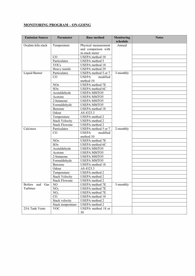
MONITORING PROGRAM – ON-GOING
Emission Source Parameter Base method Monitoring schedule
Notes
Temperature Physical measurement and comparison with in-stack meter
CO USEPA method 10 Particulates USEPA method 5 VOCs USEPA method 18
Oxalate kiln stack
Heavy metals USEPA method 29
Annual
Particulates USEPA method 5 or 7 CO USEPA modified
method 10
NOx USEPA method 7E SOx USEPA method 6C Acetaldehyde USEPA MMTO5 Acetone USEPA MMTO5 2-butanone USEPA MMTO5 Formaldehyde USEPA MMTO5 Benzene USEPA method 18 Odour AS 4323.3 Temperature USEPA method 2 Stack Velocity USEPA method 2
Liquid Burner
Stack Flowrate USEPA method 2
3-monthly
Particulates USEPA method 5 or 7 CO USEPA modified
method 10
NOx USEPA method 7E SOx USEPA method 6C Acetaldehyde USEPA MMTO5 Acetone USEPA MMTO5 2-butanone USEPA MMTO5 Formaldehyde USEPA MMTO5 Benzene USEPA method 18 Odour AS 4323.3 Temperature USEPA method 2 Stack Velocity USEPA method 2
Calciners
Stack Flowrate USEPA method 2
2-monthly
NO USEPA method 7E NO2 USEPA method 7E NOx USEPA method 7E CO USEPA method 10 Stack velocity USEPA method 2
Boilers and Gas Turbines
Stack temperature USEPA method 2
3-monthly
25A Tank Vents VOC USEPA method 18 or
30

Environmental Review and Management Programme Wagerup Refinery Unit 3 May 2005 Alcoa World Alumina Australia Page 442
Ref: ERMP Wagerup Unit 3 May 05 ENVIRON
10.2 NOISE MANAGEMENT PLAN
Noise Management Plan Wagerup Refinery Unit 3 Alcoa World Alumina Australia
NOISE MANAGEMENT PLAN
Wagerup Refinery
Date: 18 April 2005

Noise Management Plan Wagerup Refinery Unit 3 Alcoa World Alumina Australia
Table of Contents
1. Introduction......................................................................................................................... 33
2. Purpose of this Plan ............................................................................................................ 33
3. Scope of this Management Plan......................................................................................... 33
4. Project Control.................................................................................................................... 33
4.1. Preliminary Design Phase .............................................................................................. 33
4.2. Detailed Design Phase..................................................................................................... 44
4.3. Construction Phase ......................................................................................................... 44
4.4. Commissioning Phase ..................................................................................................... 55
4.5. Operational Phase ........................................................................................................... 55
5. Long Term Noise Management ......................................................................................... 66

Noise Management Plan Wagerup Refinery Unit 3 Alcoa World Alumina Australia
1. Introduction
This plan contains details of the noise control and management methods that will be employed to achieve the noise emission criteria for the Wagerup Unit Three expansion project (the Proposal). Alcoa commissioned SVT Engineering Consultants (SVT) to conduct an acoustic assessment of The Proposal. This was independently reviewed by Mrs Marian Burgess from Australian Defence Force Academy.
2. Purpose of this Plan
a) Ensure that noise emission criteria for the Wagerup Unit Three expansion (the Proposal) are met
b) Ensure incorporation of practical noise control measures in project design.
3. Scope of this Management Plan
This Noise Management Plan applies to the implementation of the Proposal from design through to commissioning and 12 months of operation. The Noise Management Plan extends to a post project completion upgrade of the refinery acoustic model and a one-off comprehensive environmental noise monitoring program
4. Project Control
4.1.Preliminary Design Phase
• Development and use of acoustic model (SoundPlan) to review impact of proposed project; use model as a tool to achieve design objectives
• Development of sound power level budget to achieve project noise emission
criteria, and
• Specification of generic noise controls to apply to all Proposal areas.

Noise Management Plan Wagerup Refinery Unit 3 Alcoa World Alumina Australia
4.2. Detailed Design Phase
• Regular review of noise-significant project elements and incorporation of
measures to control noise emissions; Regular design team noise emission reviews
• Specification of noise controls for most important sources
• Regular revision of sound power level budget as design progresses to include specific equipment items
• Preparation of noise data requisition sheets based on the updated sound power
budget for use in the design and tendering process
• Incorporation of noise specifications in contracts, for example, noise test data for specific equipment will be requested
• Revision of sound power level budget and acoustic model prior to construction
with equipment specifications provided by suppliers and
• Revision of specific noise controls for key project noise sources.
4.3. Construction Phase
• Environmental noise requirements will be included in the contractor manual for
the Project
• The Project construction manager and the site representative will have access to an acoustic consultant during the construction period, as they require
• The major portion of noisy upgrade works will be planned to occur between the
hours of 7am - 7pm, weekdays and 8am – 5pm Saturday
• Noise Management procedures will be developed for specific noisy construction processes if they are planned to occur during the night period; potentially affected residents will be notified. An acoustic consultant will conduct monitoring if noisy construction processes are planned for the night period.
• Community complaints procedure will be used to ensure any complaints
regarding environmental noise emissions during the construction period be recorded and investigated
• Noise monitoring at fixed locations will be undertaken during the construction
period.

Noise Management Plan Wagerup Refinery Unit 3 Alcoa World Alumina Australia
4.4. Commissioning Phase
• Measurement of 'noise significant' elements during commissioning will be
conducted at the source and at appropriate locations by a qualified acoustic consultant
• Follow-up assessment, design review and remedial works for items of plant that
are non-compliant with noise specifications.
• Develop action plan for any identified non-compliant refinery plant
• Development of maintenance and inspection procedures during operation to ensure acoustic controls are maintained.
4.5. Operational Phase
• Conduct one-off post construction monitoring program representative of refinery
noise emissions under 'worst case' weather conditions to verify / calibrate acoustic model (Monitoring to include representative locations which relate to the nearest residential receiver locations)
• Development of a one-off noise verification report that presents the results of
noise testing, noise monitoring and noise modelling
• One off update of noise model based on commissioning noise measurements, this will represent the as-built plant
Controls adopted from the preliminary design phase to the commissioning phase will require the implementation of the general design principles that are outlined in the document titled “Environmental Noise Management Strategy for the Wagerup 3 Expansion Project” (SVT, 2005). Where deviations are required, acoustic consultants will be involved to identify if strategies to reduce impact are required.

Noise Management Plan Wagerup Refinery Unit 3 Alcoa World Alumina Australia
5. Long Term Noise Management
Alcoa will continue to monitor noise in the vicinity of the Wagerup refinery. Fixed noise monitoring and associated data reporting is currently managed through the Part V Wagerup Refinery Licence. Alcoa conducts additional monitoring to further characterise the Refinery contribution to measured noise levels and for specific investigations, for example, to review alternative monitoring technology. Alcoa will monitor noise at locations in accordance with the licence requirements. It is anticipated that noise monitoring programs will evolve over time. Changes to monitoring programs will be discussed with the DoE. The Wagerup refinery has a long term noise management strategy that involves:
• Application for a variation to the assigned noise levels as defined in the Environmental Protection (Noise) Regulations 1997;
• Further noise reduction where reasonable and practicable;
• Continued noise monitoring and modelling;
• Noise attenuation measures for homes of people who are adversely affected by
refinery noise, if requested;
• Implementation of a land management strategy to facilitate the relocation of adversely affected people
• A complaints management program, and
• An engineering and procurement policy to adopt a ‘lowest practicable’ noise
emission approach for new or replacement plant and equipment. This long term noise management strategy has been communicated to the DoE and progress is reported in annual reports submitted to the DoE under the Part V Wagerup Licence.

Environmental Review and Management Programme Wagerup Refinery Unit 3 May 2005 Alcoa World Alumina Australia Page 449
Ref: ERMP Wagerup Unit 3 May 05 ENVIRON
10.3 WATER SUPPLY MANAGEMENT PLAN

WATER SUPPLY MANAGEMENT PLAN
Wagerup Refinery Unit 3 for
Alcoa World Alumina Australia ENVIRON Australia Pty Ltd Suite 3, Level 2 200 Adelaide Terrace East Perth, Western Australia 6004 www.environcorp.com Telephone: +618 9225 5199 Ref: WG3 Water Supply Management Plan 19 April 05.doc Facsimile: +618 9225 5155

Water Supply Management Plan Wagerup Refinery Unit 3 Alcoa World Alumina Australia Page i
Ref: U:\PR\Wagerup\WgpIII\Environment\ERMP\ERMP drafts\current draft\Final Mgmt plans\Water\Final Water Supply Management Plan v0.doc ENVIRON
TABLE OF CONTENTS
Page No.
1. INTRODUCTION.................................................................................................................... 1
2. PURPOSE AND SCOPE OF PLAN....................................................................................... 1 2.1 RELATED DOCUMENTS ........................................................................................ 1
3. BACKGROUND ...................................................................................................................... 2
4. OBJECTIVES & TARGETS.................................................................................................. 5 4.1 SUSTAINABILITY PRINCIPLES AND OBJECTIVES ....................................... 5 4.2 PUBLIC UNDERTAKINGS.................................................................................... 65 4.3 LICENCE LIMITS..................................................................................................... 6
5. WATER SUPPLY MANAGEMENT PLAN....................................................................... 76
6. WATER MONITORING PROGRAM .............................................................................. 106 6.1 ECOLOGICAL MONITORING........................................................................... 116
7. QUALITY CONTROL AND REPORTING ..................................................................... 116
8. REVIEW AND UPDATE OF MANAGEMENT PLAN .................................................. 116
9. REFERENCES..................................................................................................................... 126

Water Supply Management Plan Wagerup Refinery Unit 3 Alcoa World Alumina Australia Page ii
Ref: U:\PR\Wagerup\WgpIII\Environment\ERMP\ERMP drafts\current draft\Final Mgmt plans\Water\Final Water Supply Management Plan v0.doc ENVIRON
LIST OF TABLES
Table 1. Refinery Water Supply - CASE A – Average Rainfall/Runoff Conditions.............................. 4 Table 2. Refinery Water Supply - CASE B – Dry Rainfall/Runoff Conditions (Based on driest year on 25 years of record - 2001)...................................................................................................................... 4 Table 3. Wagerup Refinery Water Supply Licences............................................................................... 6 Table 4. Water Supply Management Measures ..................................................................................... 7 Table 5. Summary of Monitoring Program......................................................................................... 101
APPENDICES
Appendix A: Wagerup Surface Water Licence - Operational Strategy

Water Supply Management Plan Wagerup Refinery Unit 3 Alcoa World Alumina Australia Page i
Ref: U:\PR\Wagerup\WgpIII\Environment\ERMP\ERMP drafts\current draft\Final Mgmt plans\Water\Final Water Supply Management Plan v0.doc ENVIRON
GLOSSARY OF TERMS
APSS Alcoa Performance Support System CCN Community Consultation Network DoE Department of Environment DoIR Department of Industry and Resources ERMP Environmental Review and Management Programme EWR Ecological Water Requirements RDA Residue Drying Areas TDS Total Dissolved Solids measured in water as mg/L WRC Water and Rivers Commission (now part of DoE)

Water Supply Management Plan Wagerup Refinery Unit 3 19 April 2005 Alcoa World Alumina Australia Page 1
Ref: U:\PR\Wagerup\WgpIII\Environment\ERMP\ERMP drafts\current draft\Final Mgmt plans\Water\Final Water Supply Management Plan v0.doc ENVIRON
WATER SUPPLY MANAGEMENT PLAN Wagerup Refinery Unit 3
1. INTRODUCTION Alcoa’s Wagerup alumina refinery and its associated bauxite residue drying areas (RDAs) are located 120 kilometres (km) south of Perth, 2 km north of Yarloop and approximately 7 km south of Waroona. The refinery is located close to the foot of the Darling Scarp and is separated from the RDAs by the South West Highway and the Perth-Bunbury railway line. The refinery produces alumina from bauxite mined at the Willowdale mine site, using the Bayer process.
Alcoa proposes to expand its existing Wagerup alumina refinery through completing the construction of a third production unit. Construction of the third production unit will increase production from to approximately 4.7 Mtpa. An Environmental Review and Management Program (ERMP) has been prepared and submitted to the Environmental Protection Authority (EPA) for assessment under Part IV of the Environmental Protection Act 1986. This Water Supply Management Plan (WSMP) forms part of the ERMP and is included in the Appendices to the document.
2. PURPOSE AND SCOPE OF PLAN The purpose of the Water Supply Management Plan (WSMP) is to ensure that there are no adverse environmental or social impacts resulting from the refinery’s harvesting, storage and use of surface waters, and to outline water conservation initiatives for Wagerup refinery. The WSMP will document the refinery’s existing water supply system and associated operating strategy and to consider proposed modifications to the strategy that will account for changes that result from the commissioning of Wagerup Refinery Unit 3 (the Proposal). The WSMP will aim to identify any impacts that may result from these changes and propose management strategies and desired outcomes. It will also assist in identifying opportunities for continual improvement in water supply management at the Wagerup refinery. 2.1 RELATED DOCUMENTS Alcoa’s existing Surface Water Licences are supported by an Operating Strategy (Document No. 44402; see Appendix A) which was developed by Alcoa and approved by the Department of Environment. This strategy was developed in 2003 and has provisions for review prior to renewal of any of the licences and under other circumstances including changes in the refinery such as the proposed expansion.

Water Supply Management Plan Wagerup Refinery Unit 3 19 April 2005 Alcoa World Alumina Australia Page 2
Ref: U:\PR\Wagerup\WgpIII\Environment\ERMP\ERMP drafts\current draft\Final Mgmt plans\Water\Final Water Supply Management Plan v0.doc ENVIRON
The existing Surface Water Licence Operating Strategy includes a description of sources, environmental requirements, operating rules, monitoring and reporting requirements and water efficiency measures. This WSMP for the Proposal should be applied in the context of the existing Environmental Management Manual for Wagerup (Document No. 32600)1. This manual is a key document of the Wagerup Environmental Management System and the main reference document on environmental policy and principles, team structures, standards and statutory requirements, identification of environmental aspects and associated planning, management systems, procedures and environmental monitoring. This WSMP makes reference to the following documents within the APSS2 (Alcoa Performance Support System, Alcoa’s formal document management system):
• 44402 Surface Water Licence – Operational Strategy (Document No. 44402); • 53902 Surface and Storm Water Monitoring Manual (WA Operations); and • 33740 Internal Environmental Communication (Refineries).
3. BACKGROUND
The Wagerup refinery is designed to recycle all water including rainfall runoff from the refinery and residue areas. This avoids the need to discharge effluent and minimises demands on fresh water sources beyond the refinery boundary. Nevertheless, the refinery is a net user of water which it obtains from a number of licensed sources. The Proposal is expected to result in an additional demand of between 1.1 GLpa (gigalitre per annum) and 4.8 GLpa of water depending upon rainfall and the resulting runoff that occurs from existing harnessed catchments. It is proposed that the additional water for the Wagerup expansion be provided by increased harvesting of winter runoff from the Harvey River Main Drain (ENVIRON, 2005). This will be achieved by upgrading the existing pump station and delivery pipeline so that the required water can be transferred to the refinery’s water storage facilities during the winter pumping period for use during the following summer. The actual amount of water harvested in any winter period will depend upon the runoff gained from the internal refinery and residue area catchments. To accommodate the additional water Alcoa will apply to Department of Environment (DoE) to increase the withdrawal limit on the existing Harvey River Main Drain Surface Water Licence 1 As a key document related to the Wagerup Refinery Environmental Management System this document is
regularly reviewed and updated and will be subject to ongoing change. 2 All procedures within APSS are subject to change as a result of revision processes.

Water Supply Management Plan Wagerup Refinery Unit 3 19 April 2005 Alcoa World Alumina Australia Page 3
Ref: U:\PR\Wagerup\WgpIII\Environment\ERMP\ERMP drafts\current draft\Final Mgmt plans\Water\Final Water Supply Management Plan v0.doc ENVIRON
(SWL151027(2) from the current 4.4 GLpa to approximately 9.2 GLpa. An investigation of potential surface water sources and ecological water requirements by CENRM (2005) suggests that up to 28 GL of winter flow should be available from the Harvey River Main Drain during an average winter after ecological water requirements are deducted. The main water supply management activities are to monitor flow, water quality and ecological parameters in the Harvey River Main Drain downstream of the current pumping station to ensure that the winter water harvesting does not adversely impact the downstream environment. This monitoring will be undertaken prior to and after commissioning of the Wagerup expansion. Other management activities include periodic reviews of water conservation opportunities in order to minimise refinery water consumption, and maintenance of a high level of awareness within the workforce of the need to conserve water at work and at home.

Water Supply Management Plan Wagerup Refinery Unit 3 19 April 2005 Alcoa World Alumina Australia Page 4
Ref: U:\PR\Wagerup\WgpIII\Environment\ERMP\ERMP drafts\current draft\Final Mgmt plans\Water\Final Water Supply Management Plan v0.doc ENVIRON
The Wagerup Water Balance Model has been used to predict the refinery water supply for the existing
refinery and for the expanded refinery for a range of weather conditions.
Table 1. Refinery Water Supply - CASE A – Average Rainfall/Runoff Conditions
Current Refinery
(Million Litre)
Future Refinery
4.7 Mtpa
(ML?)
Moisture with Bauxite & Reagents 1,000 1,890
Rainfall collected in Fresh Water
Reservoirs
700 1,000
Rainfall Runoff from Plant Area 270 270
Rainfall Runoff & Drainage from Residue
& Liquor Pond Areas
2,390 3,330
Surface Water Sources (Licence)
- Nth & Sth Yalup Br (1,600 MLpa)
- Black Tom Br (2,500 MLpa)
- Harvey R Main Drain (4,400 MLpa)
1,200
1,500
2,100
1,200
1,500
4,300
Groundwater (Licence = 550 MLpa) 300 300
Additional Sources 1,110
Total Supplied 9,460 14,900
Table 2. Refinery Water Supply - CASE B – Dry Rainfall/Runoff Conditions (Based on driest
year on 25 years of record - 2001)
Current Refinery
(2.4 Mtpa)
Future Refinery
(4.5 Mtpa)
Moisture with Bauxite & Reagents 1,000 1,890
Rainfall collected in Fresh Water
Reservoirs
500 680
Rainfall Runoff from Plant Area 180 180
Rainfall Runoff & Drainage from Residue
& Liquor Pond Areas
1,420 1,980
Surface Water Sources (Licence)
- Nth & Sth Yalup Br (1,600 MLpa)
- Black Tom Br (2,500 MLpa)
- Harvey R Main Drain (4,400 MLpa)
200
800
4,400
200
800
4,400
Groundwater (550 MLpa) 300 300

Water Supply Management Plan Wagerup Refinery Unit 3 19 April 2005 Alcoa World Alumina Australia Page 5
Ref: U:\PR\Wagerup\WgpIII\Environment\ERMP\ERMP drafts\current draft\Final Mgmt plans\Water\Final Water Supply Management Plan v0.doc ENVIRON
Additional Sources 660 4,770
Total Supplied 9,460 14,900
4. OBJECTIVES & TARGETS
4.1 SUSTAINABILITY PRINCIPLES AND OBJECTIVES Alcoa has adopted sustainability principles and it is a requirement that these principles be considered during all new projects. The principles are as follows:
• Respect and protect people; • Build community experience and well being; • Long-term economic benefit; • Efficient resource use and cleaner production; • Ecological integrity and biodiversity; • Meeting the needs of current and future generations; • Stakeholder involvement; and • Accountability and governance.
Based upon these principles the following water supply objectives have been developed:
• Preference is given to water supply sources that are of lower quality and therefore not in competition with public water supplies.
• Refinery water supply does not adversely affect other beneficial uses of water resources in the Wagerup area including Ecological Water Requirements (EWR).
• Refinery water supply doesn’t disadvantage other water users. • Water use and supply is measured and reported in a way that is understood by all Alcoa
staff. • Refinery water conservation opportunities are identified in the water conservation plan
and regularly reviewed (Water Audit). • Water supply is achieved in ways that are consistent with the Proposed Harvey Basin
Water Allocation Plan (Water and Rivers Commission, 1998) and the State Government’s water resource management objectives.
• Alcoa staff are encouraged to practice water conservation at work and at home. • The community is involved in, understands, and supports the refinery water supply
strategy.
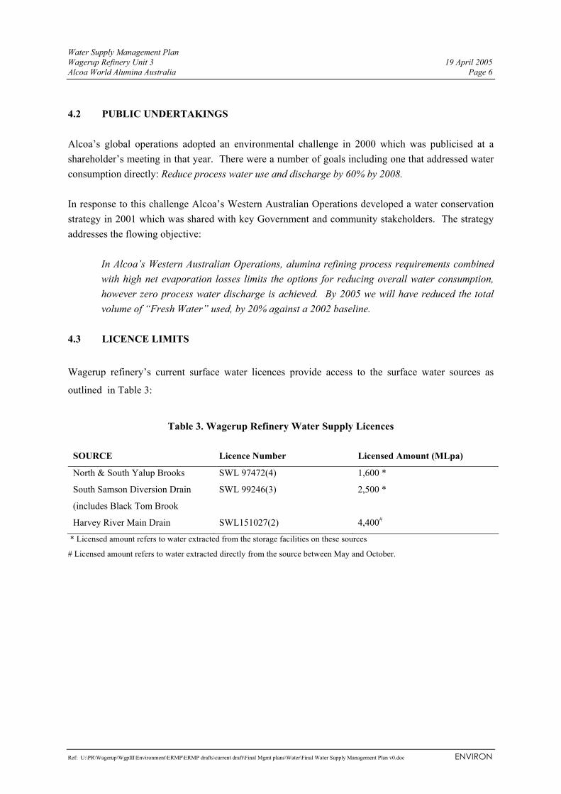
Water Supply Management Plan Wagerup Refinery Unit 3 19 April 2005 Alcoa World Alumina Australia Page 6
Ref: U:\PR\Wagerup\WgpIII\Environment\ERMP\ERMP drafts\current draft\Final Mgmt plans\Water\Final Water Supply Management Plan v0.doc ENVIRON
4.2 PUBLIC UNDERTAKINGS Alcoa’s global operations adopted an environmental challenge in 2000 which was publicised at a shareholder’s meeting in that year. There were a number of goals including one that addressed water consumption directly: Reduce process water use and discharge by 60% by 2008. In response to this challenge Alcoa’s Western Australian Operations developed a water conservation strategy in 2001 which was shared with key Government and community stakeholders. The strategy addresses the flowing objective:
In Alcoa’s Western Australian Operations, alumina refining process requirements combined with high net evaporation losses limits the options for reducing overall water consumption, however zero process water discharge is achieved. By 2005 we will have reduced the total volume of “Fresh Water” used, by 20% against a 2002 baseline.
4.3 LICENCE LIMITS
Wagerup refinery’s current surface water licences provide access to the surface water sources as
outlined in Table 3:
Table 3. Wagerup Refinery Water Supply Licences
SOURCE Licence Number Licensed Amount (MLpa)
North & South Yalup Brooks SWL 97472(4) 1,600 *
South Samson Diversion Drain
(includes Black Tom Brook
SWL 99246(3) 2,500 *
Harvey River Main Drain SWL151027(2) 4,400#
* Licensed amount refers to water extracted from the storage facilities on these sources
# Licensed amount refers to water extracted directly from the source between May and October.
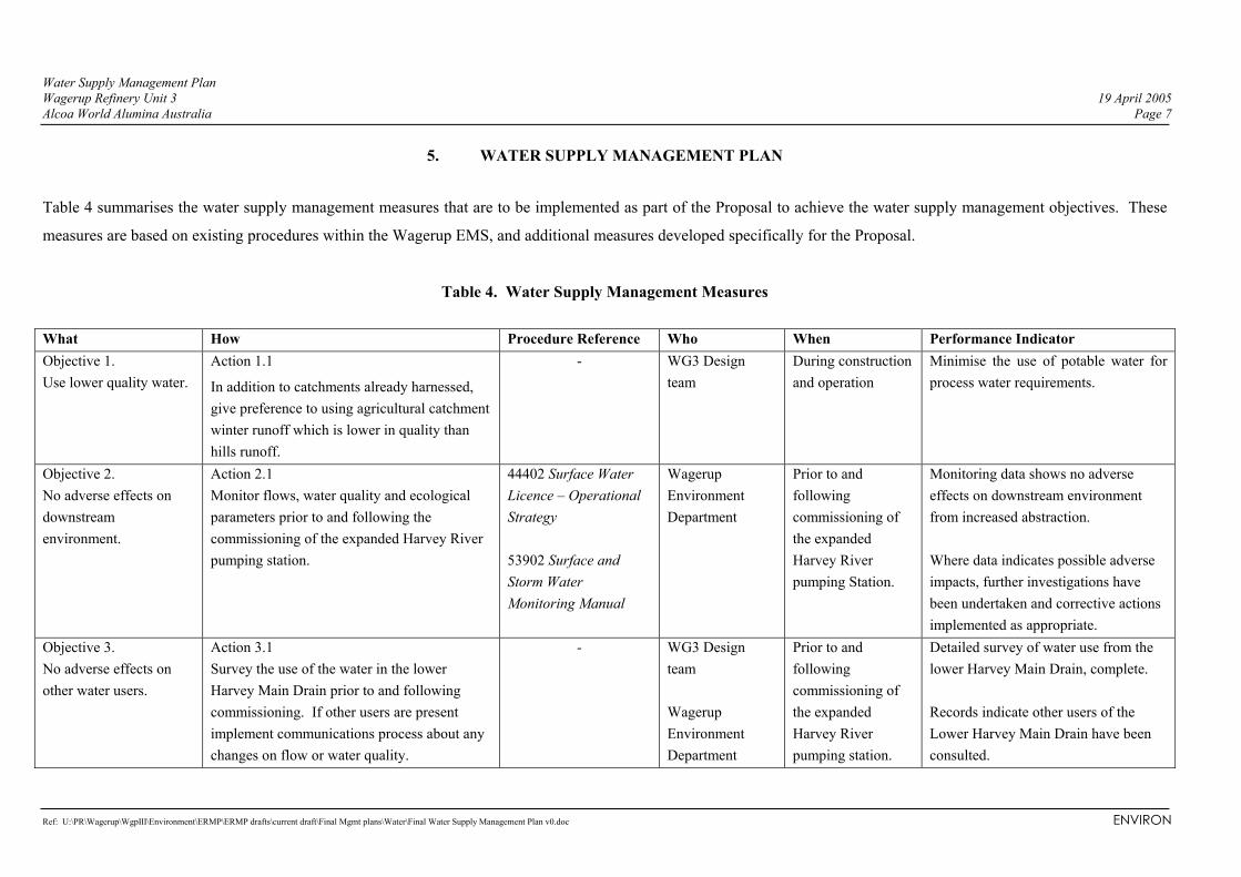
Water Supply Management Plan Wagerup Refinery Unit 3 19 April 2005 Alcoa World Alumina Australia Page 7
Ref: U:\PR\Wagerup\WgpIII\Environment\ERMP\ERMP drafts\current draft\Final Mgmt plans\Water\Final Water Supply Management Plan v0.doc ENVIRON
5. WATER SUPPLY MANAGEMENT PLAN
Table 4 summarises the water supply management measures that are to be implemented as part of the Proposal to achieve the water supply management objectives. These
measures are based on existing procedures within the Wagerup EMS, and additional measures developed specifically for the Proposal.
Table 4. Water Supply Management Measures
What How Procedure Reference Who When Performance Indicator Objective 1. Use lower quality water.
Action 1.1
In addition to catchments already harnessed, give preference to using agricultural catchment winter runoff which is lower in quality than hills runoff.
- WG3 Design team
During construction and operation
Minimise the use of potable water for process water requirements.
Objective 2. No adverse effects on downstream environment.
Action 2.1 Monitor flows, water quality and ecological parameters prior to and following the commissioning of the expanded Harvey River pumping station.
44402 Surface Water Licence – Operational Strategy 53902 Surface and Storm Water Monitoring Manual
Wagerup Environment Department
Prior to and following commissioning of the expanded Harvey River pumping Station.
Monitoring data shows no adverse effects on downstream environment from increased abstraction. Where data indicates possible adverse impacts, further investigations have been undertaken and corrective actions implemented as appropriate.
Objective 3. No adverse effects on other water users.
Action 3.1 Survey the use of the water in the lower Harvey Main Drain prior to and following commissioning. If other users are present implement communications process about any changes on flow or water quality.
- WG3 Design team Wagerup Environment Department
Prior to and following commissioning of the expanded Harvey River pumping station.
Detailed survey of water use from the lower Harvey Main Drain, complete. Records indicate other users of the Lower Harvey Main Drain have been consulted.

Water Supply Management Plan Wagerup Refinery Unit 3 19 April 2005 Alcoa World Alumina Australia Page 8
Ref: U:\PR\Wagerup\WgpIII\Environment\ERMP\ERMP drafts\current draft\Final Mgmt plans\Water\Final Water Supply Management Plan v0.doc ENVIRON
What How Procedure Reference Who When Performance Indicator
Objective 4. Water use and supply is measured.
Action 4.1 Measure major use and supply of fresh water to facilitate analysis for efficiency improvements and reporting.
44402 Surface Water Licence – Operational Strategy
All operational areas.
Ongoing, with data reported annually to DoIR/DoE
Water use and supply data reported annually.
Objective 5. Conduct regular reviews or audits of water supply and consumption.
Action 5.1 Review the status of major water conservation opportunities and update the Operating Strategy to reflect these.
44402 Surface Water Licence – Operational Strategy
Wagerup Environment Department
Five-yearly or: • 3 months prior
to expiry of surface water licences;
• If monitoring indicated adverse trends/unexpected performance; or
• If a substantial change occurs to the refinery’s assets, water requirements, releases and/or other purpose of surface water diversion or use.
Schedule of Amendments indicates Operating Strategy reviewed as required.
Objective 6. Action 6.1 44402 Surface Water Wagerup Prior to Operating Strategy has been reviewed
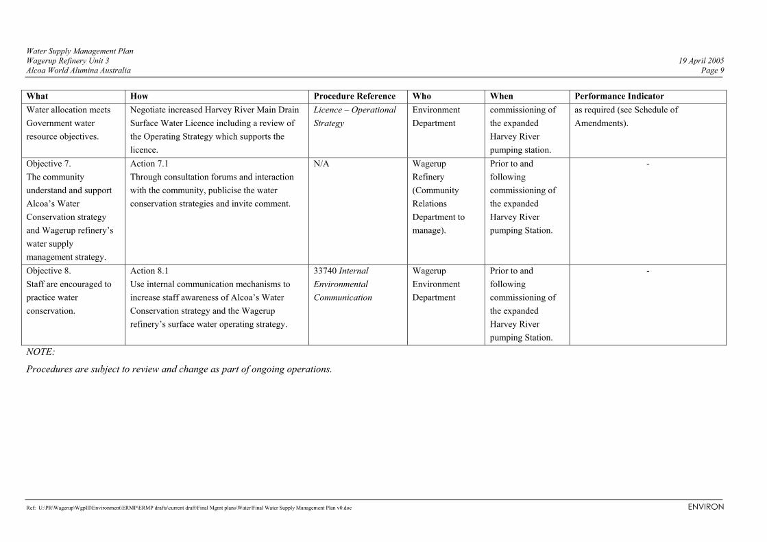
Water Supply Management Plan Wagerup Refinery Unit 3 19 April 2005 Alcoa World Alumina Australia Page 9
Ref: U:\PR\Wagerup\WgpIII\Environment\ERMP\ERMP drafts\current draft\Final Mgmt plans\Water\Final Water Supply Management Plan v0.doc ENVIRON
What How Procedure Reference Who When Performance Indicator Water allocation meets Government water resource objectives.
Negotiate increased Harvey River Main Drain Surface Water Licence including a review of the Operating Strategy which supports the licence.
Licence – Operational Strategy
Environment Department
commissioning of the expanded Harvey River pumping station.
as required (see Schedule of Amendments).
Objective 7. The community understand and support Alcoa’s Water Conservation strategy and Wagerup refinery’s water supply management strategy.
Action 7.1 Through consultation forums and interaction with the community, publicise the water conservation strategies and invite comment.
N/A Wagerup Refinery (Community Relations Department to manage).
Prior to and following commissioning of the expanded Harvey River pumping Station.
-
Objective 8. Staff are encouraged to practice water conservation.
Action 8.1 Use internal communication mechanisms to increase staff awareness of Alcoa’s Water Conservation strategy and the Wagerup refinery’s surface water operating strategy.
33740 Internal Environmental Communication
Wagerup Environment Department
Prior to and following commissioning of the expanded Harvey River pumping Station.
-
NOTE:
Procedures are subject to review and change as part of ongoing operations.

Water Supply Management Plan Wagerup Refinery Unit 3 19 April 2005 Alcoa World Alumina Australia Page 10
Ref: U:\PR\Wagerup\WgpIII\Environment\ERMP\ERMP drafts\current draft\Final Mgmt plans\Water\Final Water Supply Management Plan v0.doc ENVIRON
6. WATER MONITORING PROGRAM
Table 5. Summary of Monitoring Program
Location Parameter Method/Frequency
SP1 - North Yalup Brook Flow volume Weir with level probes reading continuously
and recorded on a logger. Data downloaded
monthly.
Upper Yalup Dam Offtake Volume extracted In-line magnetic flow meters.
Detention Pond Pump Station Volume extracted In-line magnetic flow meters.
Harvey River Main Drain Pump Station Volume extracted
Water Chemistry (pH, TDS,
Total N & P)
In-line magnetic flow meters.
Grab sample Monthly when pumping
SP5 Detention Pond #1 Overflow Release/Overflow volume Weir with level probes reading continuously
and recorded on a logger. Data downloaded
monthly.
SP12 Samson South Diversion Drain Chemical parameters (as per
the DoE licence in effect at
time)
Metals (as per the DoE licence
in effect at time)
Release/Overflow volume
Monthly – when flowing
Grab Sample Six-monthly
Weir with level probes reading continuously
and recorded on a logger. Data downloaded
monthly.
SP14 Samson North Drain * Water Chemistry (pH, TDS,
Total N&P)
Flow volume
Grab Sample Monthly when flowing
Level probes reading continuously and
recorded on a logger. Data downloaded
monthly.
Flow rating for control section used to
estimate flow. Flow monitoring station being
upgraded by DoE. Alcoa to cooperate with
DoE to gain data
SP20 Harvey River Main Drain Flow volume
Water Chemistry
Level probes reading continuously and
recorded on a logger. Data downloaded
monthly.
Flow rating for control section used to
estimate flow.

Water Supply Management Plan Wagerup Refinery Unit 3 19 April 2005 Alcoa World Alumina Australia Page 11
Ref: U:\PR\Wagerup\WgpIII\Environment\ERMP\ERMP drafts\current draft\Final Mgmt plans\Water\Final Water Supply Management Plan v0.doc ENVIRON
6.1 ECOLOGICAL MONITORING In line with the principle of Adaptive Environmental Assessment and Management (AEAM) ecological water requirements (EWR) evaluations have been conducted on all streams and drains that provide water sources for the Wagerup Refinery by CENRM The EWR study was updated for the Harvey River Main Drain as part of the ERMP preparation
(CENRM, 2005). The study includes recommendations for more detailed ecological monitoring prior
to the Wagerup Expansion.
7. QUALITY CONTROL AND REPORTING
This WSMP will be incorporated into Wagerup’s ISO 14001 Environmental Management System
which is independently reviewed.
Progress against the action plan will be reported in the Review of Impact on Waters Report which is
submitted to DoE and DoIR by the 31 March each year.
8. REVIEW AND UPDATE OF MANAGEMENT PLAN
This management plan will be reviewed every five years, or:
• three months prior to expiry of surface water licences;
• if monitoring or annual reporting indicate adverse trends or unexpected performance;
• if a substantial change occurs to the refinery’s assets, water requirements, releases and/or
purpose of surface water diversion or use; or
• if directed by the DoE.
Water Supply Management Plan Wagerup Refinery Unit 3 19 April 2005 Alcoa World Alumina Australia Page 12
Ref: U:\PR\Wagerup\WgpIII\Environment\ERMP\ERMP drafts\current draft\Final Mgmt plans\Water\Final Water Supply Management Plan v0.doc ENVIRON
9. REFERENCES
ENVIRON Australia Pty Ltd (2005). Water Supply Study, Wagerup Refinery Unit 3. Report
prepared for Alcoa World Alumina Australia.
CENRM (2005). Ecological Water Requirements and water availability in the lower Harvey River
catchment associated with the proposed Wagerup 3 Expansion. Report prepared for
Alcoa World Alumina Australia.
Water and Rivers Commission (1998). Proposed Harvey Basin Water Allocation Plan.

Water Supply Management Plan Wagerup Refinery Unit 3 19 April 2005 Alcoa World Alumina Australia Page 13
Ref: U:\PR\Wagerup\WgpIII\Environment\ERMP\ERMP drafts\current draft\Final Mgmt plans\Water\Final Water Supply Management Plan v0.doc ENVIRON
Appendix A
Wagerup Surface Water Licence - Operational Strategy

Environmental/Licences
Surface Water Licence - Operational Strategy (WGP)
Wagerup
AOA Document No: 44402 Version: 5 Issue Date: 13/01/05
Author: Sarah Williamson Authoriser: Anita Logiudice
Document is valid until: DATE+1WK /1234567890
Page 1 of 19
Alcoa World Alumina – Australia WAGERUP REFINERY Surface Water Licence
OPERATIONAL STRATEGY 4th Revision January 2005
This Operational Strategy forms part of Surface Water Licences issued to Alcoa World Alumina - Australia under the Rights in Water and Irrigation Act (1914), for the Wagerup Refinery located within the Harvey River Basin. Originally three licences were granted and they set conditions under which Alcoa could divert surface water from the Samson Brook South Channel (Lic No. 97471), Black Tom Brook (Lic No. 99246) and Yalup Brook (Lic No. 97472) catchments. The Samson Brook South Channel catchment and Black Tom Brook are located within the proclaimed Waroona Irrigation District, while Yalup Brook is located within the boundaries of the proclaimed Harvey Irrigation District. The licences included an interim allocation to be replaced by development of a long-term supply. To replace the interim allocation of 1,700 ML/yr from the Samson Brook South Channel and Black Tom Brook Catchments, and to meet the Refinery’s expected water demand during dry years, Alcoa investigated several long-term water supply options. Long-term options included: i. A trade in water allocation with SWI, giving Alcoa entitlement to stored water from the
Samson and Drake’s Brook Dams. ii. Accessing groundwater iii. Demonstrate that additional water from the hills catchment is available beyond current
allocations iv. Pump from Harvey Main Drain v. Pump back from the end of the Diversion Drain. vi. Pump back from Samson North Drain vii. Cross site agreement with WC viii. Conversion of farmlands irrigation allocation The Harvey River Pump Back Station (Lic No 151027) was approved and commissioned at the start of winter 2003 to be utilised as a long-term water supply option for the Wagerup Refinery. Both the Black Tom Brook and Yalup Brook Licences were retained, however water can no longer be drawn from the Samson Brook South Channel. Water diverted by Wagerup Refinery is stored in the existing Upper and Lower Yalup Dams, Detention Pond, and the refinery’s Run-off Water Storage Pond (ROWS Pond). The refinery for the purpose of providing potable water, process makeup water and for residue area dust suppression diverts surface water.

Environmental/Licences
Surface Water Licence - Operational Strategy (WGP)
Wagerup
AOA Document No: 44402 Version: 5 Issue Date: 13/01/05
Author: Sarah Williamson Authoriser: Anita Logiudice
Document is valid until: DATE+1WK /1234567890
Page 2 of 19
1. Administrative Requirements
1.1 Duration of strategy This strategy shall be current for five years commencing at the time of licence approval and ceasing 31st December 2007. The strategy shall be reviewed under the following circumstances:
• Three months prior to expiry of surface water licences.
• If monitoring or annual reporting indicate adverse trends or unexpected performance.
• If a change occurs to the refinery’s assets, water requirements, releases and/or purpose of surface water diversion or use.
If directed by the Department of Environment (DoE) following consultation with Alcoa.
1.2 Description of source & diversion points Figures 1 and 2 show the various water catchments and diversion points described below.

Environmental/Licences
Surface Water Licence - Operational Strategy (WGP) Wagerup
AOA Document No: 44402 Version: 5 Issue Date: 13/01/05
Author: Sarah Williamson Authoriser: Anita Logiudice
Document is valid until: DATE+1WK /1234567890
Page 3 of 19
Figure 1 Harvey River Catchment

Environmental/Licences
Surface Water Licence - Operational Strategy (WGP) Wagerup
AOA Document No: 44402 Version: 5 Issue Date: 13/01/05
Author: Sarah Williamson Authoriser: Anita Logiudice
Document is valid until: DATE+1WK /1234567890
Page 4 of 19
Figure 2 – Black Tom Brook and South Samson Brook Catchment
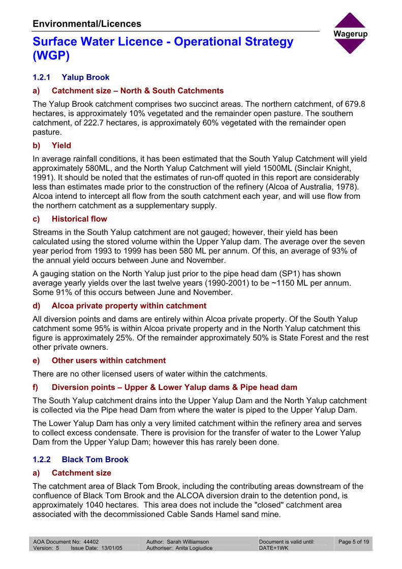
Environmental/Licences
Surface Water Licence - Operational Strategy (WGP)
Wagerup
AOA Document No: 44402 Version: 5 Issue Date: 13/01/05
Author: Sarah Williamson Authoriser: Anita Logiudice
Document is valid until: DATE+1WK /1234567890
Page 5 of 19
1.2.1 Yalup Brook a) Catchment size – North & South Catchments The Yalup Brook catchment comprises two succinct areas. The northern catchment, of 679.8 hectares, is approximately 10% vegetated and the remainder open pasture. The southern catchment, of 222.7 hectares, is approximately 60% vegetated with the remainder open pasture. b) Yield In average rainfall conditions, it has been estimated that the South Yalup Catchment will yield approximately 580ML, and the North Yalup Catchment will yield 1500ML (Sinclair Knight, 1991). It should be noted that the estimates of run-off quoted in this report are considerably less than estimates made prior to the construction of the refinery (Alcoa of Australia, 1978). Alcoa intend to intercept all flow from the south catchment each year, and will use flow from the northern catchment as a supplementary supply. c) Historical flow Streams in the South Yalup catchment are not gauged; however, their yield has been calculated using the stored volume within the Upper Yalup dam. The average over the seven year period from 1993 to 1999 has been 580 ML per annum. Of this, an average of 93% of the annual yield occurs between June and November. A gauging station on the North Yalup just prior to the pipe head dam (SP1) has shown average yearly yields over the last twelve years (1990-2001) to be ~1150 ML per annum. Some 91% of this occurs between June and November. d) Alcoa private property within catchment All diversion points and dams are entirely within Alcoa private property. Of the South Yalup catchment some 95% is within Alcoa private property and in the North Yalup catchment this figure is approximately 25%. Of the remainder approximately 50% is State Forest and the rest other private owners. e) Other users within catchment There are no other licensed users of water within the catchments. f) Diversion points – Upper & Lower Yalup dams & Pipe head dam The South Yalup catchment drains into the Upper Yalup Dam and the North Yalup catchment is collected via the Pipe head Dam from where the water is piped to the Upper Yalup Dam. The Lower Yalup Dam has only a very limited catchment within the refinery area and serves to collect excess condensate. There is provision for the transfer of water to the Lower Yalup Dam from the Upper Yalup Dam; however this has rarely been done.
1.2.2 Black Tom Brook a) Catchment size The catchment area of Black Tom Brook, including the contributing areas downstream of the confluence of Black Tom Brook and the ALCOA diversion drain to the detention pond, is approximately 1040 hectares. This area does not include the "closed" catchment area associated with the decommissioned Cable Sands Hamel sand mine.

Environmental/Licences
Surface Water Licence - Operational Strategy (WGP)
Wagerup
AOA Document No: 44402 Version: 5 Issue Date: 13/01/05
Author: Sarah Williamson Authoriser: Anita Logiudice
Document is valid until: DATE+1WK /1234567890
Page 6 of 19
b) Yield / Historical Flow The Water and Rivers Commission operated a stream flow gauging station in the upper reaches of Black Tom Brook between 1981 and 1982. Flow data from this station correlates well with the observed flow at the Water and Rivers Commission stream flow gauging station on McKnoes Brook, to the north. The two data sets were used to generate monthly flows for the Black Tom Brook catchment between 1980 and 1999. The estimated mean annual flow of the Black Tom Brook catchment is 4100 ML. The estimated 10 and 90 percentile annual flows are 3100 and 5200 ML respectively. Limited data from station SP6 (since 1997) indicates that these yields are not being achieved. The mean flow recorded is 1770 ML (1997-2001). c) Other major users within catchment Majority of the catchment is state forest. Several small private farming lots exist in the lower portion of the catchment as well as the decommissioned Cable Sands Hamel sand mine. There are no other licensed water users within the catchment. d) Diversion point The main channel of Black Tom Brook discharges into the diversion drains approximately 2.5 km upstream of the Alcoa Detention Pond. The southwest portion of the catchment has been significantly modified and is said to drain towards the Diversion Drain and Alcoa’s Detention Pond.
1.2.3 Harvey River a) Catchment size - Upstream of Logue Brook Drain This catchment area can be described as the immediate catchment of the portion of Harvey River from the Harvey River New Dam to the abstraction point. The townsite of Harvey falls within the catchment. Other than the channel itself, the catchment area only contains one tributary, which is unnamed. The catchment area is approximately 280 km2 measured from Bristol Road with approximately 35% of the catchment in the scarp/hills area. b) Yield / Historical Flow Alcoa ran a gauging station at Bristol Road between 1977 and 1986 with quality data available for the period between 1984 to 1986. Water and Rivers Commission flow data is available from Clifton Park (613052) and this has been used to back-calculate to Bristol Road – Streamtec 2002. The estimated mean annual flow past the diversion point is around 75 GL. c) Alcoa Private property within catchment The diversion point is located within the Harvey River easement and within the catchment there is minor Alcoa Property. d) Other major users within catchment The Harvey River is used primarily as a drainage channel for removing excess irrigation water and a final pathway to drain agricultural land. There are no other major licensed users either upstream or downstream from the abstraction point.

Environmental/Licences
Surface Water Licence - Operational Strategy (WGP)
Wagerup
AOA Document No: 44402 Version: 5 Issue Date: 13/01/05
Author: Sarah Williamson Authoriser: Anita Logiudice
Document is valid until: DATE+1WK /1234567890
Page 7 of 19
e) Diversion point A pumping station situated on the southern bank of the Harvey River immediately downstream of the confluence with Logue Brook drain. Water will be pumped via a pipeline to the Wagerup residue area. Discharge will be into either the runoff water storage pond (ROWS) or the Detention Pond.
Table 1 Surface Water Storage Details Name Location
AMG Storage capacity
m3 x 103
Land ownership at storage
Source Volume to be diverted m3 x 103
6358150 N399100 E
1595 Alcoa South Yalup 580 Upper Yalup Dam
North Yalup 1020
Lower Yalup Dam
6358278 N398145 E
675 Alcoa NA NA
Pipe head Dam
6358893 N399480 E
14 Alcoa North Yalup 1020
Detention Pond
6358900 N396500 E
1745 Alcoa Black Tom Harvey River
2500 *
ROWS 6357250 N396250 E
5000 Alcoa Harvey River *
* Combined maximum 4400
1.3 Reporting To meet the reporting requirements of the Operational Strategy, annual reporting will be incorporated into Alcoa’s Annual Impacts on Waters Report for the Wagerup Refinery. The review is submitted annually to DRD in accordance with the Alumina Refinery (Wagerup) Agreement Act 1978. DRD distribute the review document to the DoE and other relevant government agencies for comment. The review covers a calendar year (1st January to 31st December) and is submitted by 31st March each year, for the previous year’s reporting. To meet the requirements of the operational strategy, the following information will be reported within the Impacts on Waters Report:
• Volume of water drawn from storage by Alcoa from the various sources during the reporting period.
• Volume released downstream from diversion/storage points (including excess winter flow releases & environmental releases) during the reporting period.
• Surface water quality data.

Environmental/Licences
Surface Water Licence - Operational Strategy (WGP)
Wagerup
AOA Document No: 44402 Version: 5 Issue Date: 13/01/05
Author: Sarah Williamson Authoriser: Anita Logiudice
Document is valid until: DATE+1WK /1234567890
Page 8 of 19
• Reporting the refinery water circuit and surface water inventory for that year.
• Reporting of adverse trends or unexpected performance noted during reporting period.
• Breaches of operating strategy and corresponding remedial actions.
• Evaluation of water efficiency and initiatives taken during the reporting period.
• Rainfall data.
• Brief discussion of effectiveness of the monitoring program to ensure compliance with the DoE surface water licence conditions.
• Outline of any likely changes to the refinery water requirements / operational strategy for next reporting period.
1.4 Action taken in the event of a breach of Operating Strategy As the Operational Strategy forms part of the Surface Water Licences, any breach of the strategy constitutes a breach under Section 13 of the Rights in Water and Irrigation Act 1914. Alcoa is therefore required to report any such breach to the DoE within 14 days of the monitoring results becoming available. In the event of a breach, Alcoa will immediately undertake corrective action if required following negotiations with the DoE and other relevant government agencies. All remedial actions will be documented and reference made to any breaches in the annual report for that water year.
Department of Environment Contact Notification to DoE should be directed to
DoE – Kwinana Peel Region A/Program Manager- Allocation Alan Cook PO Box 454 Kwinana WA 6167 Phone: (08) 9411 1777 Fax: (08) 9419 5897
Wagerup Refinery Contact Environmental Manager – Wagerup Richard Bailey PO Box 84 Waroona WA 6215 Phone (08) 9733 8119 Fax (08) 97338534

Environmental/Licences
Surface Water Licence - Operational Strategy (WGP)
Wagerup
AOA Document No: 44402 Version: 5 Issue Date: 13/01/05
Author: Sarah Williamson Authoriser: Anita Logiudice
Document is valid until: DATE+1WK /1234567890
Page 9 of 19
2. Environmental Requirements
2.1 Local Catchment EWRs To minimise the adverse impact of surface water diversion by the Wagerup Refinery on the downstream environment and other users, Alcoa has undertaken an environmental water requirements (EWRs) study of the local catchments and a follow up assessment. The study area included: 1. Below Pipe head Dam on the north tributary of Yalup Brook 2. Downstream of the Lower Yalup Dam on the south tributary of Yalup Brook 3. Downstream of confluence of Samson Brook South Channel and the Diversion Drain to
the Harvey Main Drain. The initial study focused on the potential local impacts associated with the various diversion structures associated with the refinery water supply system. The results of this study have been documented in the following report: Streamtec (May 2000) Yalup & Samson Brook: Environmental Water Requirements, Streamtec Report 07/00. A follow up study was undertaken during 2001 to assess any impacts caused by the diversion of water. The results of this study are documented in the following report: Streamtec (April 2002) YalupBrooks & South Samson Drain: Adequacy of Environmental Water Provisions: Results from Biomonitoring, Streamtec Report 04/02 Both reports reinforced that the historical and continued abstraction of water from these systems was not having an adverse effect on their ecological health.
2.2 Harvey River Basin EWRs The above mentioned studies did not take into account the EWRs determined for the greater Harvey River Basin, which were documented in the Water and Rivers Commission Report WRAP 14 (1998) Proposed Harvey Basin Surface Water Allocation Plan. The Wagerup Refinery falls within the Harvey River Basin. Allocation of surface water resources in this area need to take into consideration the management guidelines set in the 1998 Allocation Plan. The plan identifies the ecological importance of flow from the forested scarp catchments reaching the lower river system and Harvey Estuary. The report “Assessment of proposed water abstraction from the Lower Harvey River” Streamtec 2002, submitted to support the licence application for abstraction from the Harvey River, includes a desktop analysis of EWR requirements for the Harvey River. An EWR of 3.3 GL/y has been calculated at the abstraction point.

Environmental/Licences
Surface Water Licence - Operational Strategy (WGP)
Wagerup
AOA Document No: 44402 Version: 5 Issue Date: 13/01/05
Author: Sarah Williamson Authoriser: Anita Logiudice
Document is valid until: DATE+1WK /1234567890
Page 10 of 19
3. Operating Rules
3.1 Water Allocation Alcoa has received the following licences for the long-term allocation of surface water to sustain the Wagerup Refinery at the current alumina production capacity of 2.4 Mtpa. The projected allocation for a refinery capacity of 3.3 Mtpa is also included below.
Table 2: Summary of Water Source Allocation Alumina Production 2.4 Mtpa 3.3 Mtpa
Water Source Water Allocation (ML)
Yalup Brook 1,600 1,600 Black Tom Brook 2,500 *1 2,500 *1 Harvey Main Drain 4,400 *2 6,000 *3
*1 Allocation may not be available under dry conditions. *2 Allocation can only be drawn between May and October *3 This allocation is proposed only and will be formalised, if required, via the normal
application and approval process for surface water allocation. Historical data indicates that even under average conditions the full allocation from the Yalup or Black Tom catchments may not be available. Therefore the Harvey allocation needs to be robust enough to meet all non-potable needs. Licences for Yalup and Black Tom Brooks are measured as draw from storage. Until expanded refinery capacity is implemented there will be no dedicated storage for water from the Harvey River. The licence to take water from the Harvey River applies to the point at which water is pumped from the River. This flow is metered from the pipeline, down stream from the pump, but prior to the control point that determines whether flow is diverted to the ROWS pond or the detention pond. It is critical that flow volumes to either the ROWS Pond or the Detention pond can be determined, to prevent double counting of water from the Detention Pond for when the water is diverted into it from the Harvey River.

Environmental/Licences
Surface Water Licence - Operational Strategy (WGP)
Wagerup
AOA Document No: 44402 Version: 5 Issue Date: 13/01/05
Author: Sarah Williamson Authoriser: Anita Logiudice
Document is valid until: DATE+1WK /1234567890
Page 11 of 19
3.2 Operating Protocol
3.2.1 Description of Water Circuit
Sand Lake
R D A 1
R D A 5
R D A 2
R D A 3
R D A 4
R D A 6
R ain/E vap
R ain/E vap
Rain/E va p
R ain/E vap
R ain/E vap
R ainB auxiteC austic
P lan t E vapH ydrate
C ooling Tow ers
Sand R esidue
M udThickened M
udU nderdrainage
R D A R ainfall Run-offD ecant R etu rn W ater
Cooling Circuit
Rainfall R
un-off
Irrigation Sprinklers
M ake-up W ater
PotableW ater
O verF low
R ain/E vap
REFINERY
U pper D am
Low er D am
COOLINGPOND
RUN-OFFSTORAGEPOND
D eten tionPond
E xcessC ondensate
S torm Surge PondSew erage ponds
R D A 7
B auxite Stockpile/ conveyor runoff
FIGURE 3 Overview of the Water Circuit
The overall water circuit is shown schematically in Figure 3. It is a “closed” water circuit, with all rainfall run-off from the refinery, residue storage areas and process water ponds transferred to the Run-off Storage Pond during winter and then used as make-up water for the refinery during summer. Losses from the process are primarily through evaporation, although there is a relatively high portion of water retained with the residue after it has been dry stacked. All of the residue storage areas have base drainage systems, and these systems collect residue leachate and rainfall infiltration, which is also returned to the refinery as make-up water.
3.2.2 Yalup Catchment The refinery’s historical diversion of 1,600 ML/yr from the Yalup Catchment may continue for the long-term as “existing industrial use”, as implied under the management guidelines set for Management Area 5 of the Harvey Basin Allocation Plan (Northern Unregulated and Semi-regulated Darling Range Streams). a) North Yalup – Pipe Head Dam The Pipe head Dam collects all flow from the North Yalup Brook from where it is transferred to the Upper Yalup Dam. An amount of water is maintained in the Pipe head Dam for stock watering purposes. An overflow spillway exists to facilitate excess water accumulating in storm events. A dump mechanism can be used to drain the dam. As all of the South Yalup catchment will be harvested, only an amount to make a total of 1600 ML will be taken from the North Yalup Catchment. Any surplus yield will be allowed to bypass the Pipe head Dam or enter and overflow the Upper Yalup Dam. Bypass or overflow will flow through Alcoa land towards the refinery area until being diverted to the Samson South Diversion Drain, which flows to the Harvey Main Drain.

Environmental/Licences
Surface Water Licence - Operational Strategy (WGP)
Wagerup
AOA Document No: 44402 Version: 5 Issue Date: 13/01/05
Author: Sarah Williamson Authoriser: Anita Logiudice
Document is valid until: DATE+1WK /1234567890
Page 12 of 19
No formal releases are required for EWRs as existing flows from the local catchment and small tributaries are considered adequate to meet the EWRs for the section of watercourse downstream of the Pipe head Dam (see Section 4 of Streamtec Report). b) South Yalup Catchment – Upper Yalup Dam & Lower Yalup Dam The Upper Yalup Dam receives direct runoff from the South Yalup Catchment. All runoff is collected. There is provision to transfer water to the Lower Yalup Dam; however this is not normally done. Water in the Upper Yalup Dam is used primarily as potable water for the refinery. No formal releases are required to meet local EWRs. The ecological value of the few river pools present can be maintained by existing local run-off (see Section 4 of Streamtec Report).
3.2.3 Black Tom Brook Over the past 6 years the refinery has diverted, on average 2,500 ML/yr (based on those years of highest draw). In light of the management guidelines set for Management Area 5 of the Harvey Basin Allocation Plan (Northern Unregulated and Semi-regulated Darling Range Streams) the refinery may continue to divert up to 2,500 ML/yr for the long-term from the Black Tom Catchment as “existing industrial use”. Water harvested from the Black Tom Brook catchments is stored in the Detention Pond located on the Samson South Diversion Drain, with some of the intercepted water transferred to the Run-off Water Storage Pond (ROWs Pond). This water is used primarily as make-up water to the refining process, but also provides irrigation water for dust suppression on the residue drying beds. A facility has been installed to transfer water from the Detention Pond to the Upper Yalup Dam to supplement potable water supplies. The un-allocated portion of winter flow draining from the Samson Brook South Channel, Black Tom Brook and North Yalup Catchments overflows the Alcoa Detention Pond into the Diversion Drain. This drain discharges into the Samson Brook South Channel, just upstream of SP12 (see Figure 1). The ecological water requirements study completed by Streamtec recommends a flow of 3,010 ML/annum to maintain the ecology at a low level of risk, for the portion of Samson Brook South Channel between SP12 and the Harvey River Main Drain. It is believed that flows from the Samson Brook North Channel are likely to meet this EWR requirement. SP14 represents Alcoa’s monitoring point on the Samson Brook North Channel (see Figure 1).
3.2.4 Harvey River The Harvey River catchment area that feeds the diversion point is around 20,000 hectares. Of this about 35% is forest and the remainder is primarily cleared agricultural ground. River flows are comprised of winter runoff from hills catchments north of the Harvey Dam and south of the Yalup catchment and drainage from irrigated pasture during winter and summer. The diversion of 4.4GL represents less than 5% of the total modelled flow. The pump inlet design allows for at least 200mm river depth to pass before the pumping can start. These base flows will adequately meet and exceed flows required for EWRs. Pumping rates will be variable depending on the total river flow. As the river flow rises above the base flow rate the four pumps will cut in sequentially to provide a maximum pumping rate of 465 l/sec. The pipeline discharge can be directed to either of the ROWS or Detention Ponds depending on system requirements.

Environmental/Licences
Surface Water Licence - Operational Strategy (WGP)
Wagerup
AOA Document No: 44402 Version: 5 Issue Date: 13/01/05
Author: Sarah Williamson Authoriser: Anita Logiudice
Document is valid until: DATE+1WK /1234567890
Page 13 of 19
The preferred storage is the Detention Pond as this will allow the water to be used not only as process make-up water but for summer dust suppression or even as a top-up for the Upper Yalup Dam. Until the Detention Pond can be expanded however there will need to be some transfer to the ROWS pond towards the end of winter to ensure adequate storage for all needs during the summer. Alcoa is only permitted to draw water from the Harvey River between May and October, or otherwise directed by the Water and Rivers Commission.
3.2.5 Proposed Closure of Samson South Drain During the initial planning for the refinery and residue storage areas, it was recognised that construction of the residue areas would block much of the normal east-west drainage across Alcoa’s property. To maintain efficient drainage for the area east of the residue area, a diversion drain was constructed around the eastern and southern sides of the property. It was planned that this drain would eventually replace the function of the portion of the Samson South Drain that was located across the northern part of Alcoa’s property. It was anticipated that closure of the drain would be required to facilitate future expansion of the residue storage areas. The existing agricultural drains were designed by the PWD to prevent inundation of pasture for extended periods of time rather than prevent all flooding. To reflect this philosophy, the drains were designed to handle peak flows with a recurrence interval of two years below the natural ground surface, and a recurrence interval of ten years to be contained below the banks of the drain. The South Samson Diversion Drain was designed on these same principles (Alcoa of Australia, 1980). Design flows for the drain were derived by dividing the catchment into three sections: 1. Upstream of Black Tom Brook (1730 Ha) 2. From Black Tom Brook to Yalup Brook which includes the Detention Pond (1750 Ha) 3. From Yalup Brook to Bancell drain (655 Ha) Unit hydrographs for two-year and ten-year storms were applied to the catchment, and the diversion drain cross sections designed to meet the PWD flow requirements. Structures within the drain were all designed for the ten-year peak flows. These included:
• Culverts under Fawcett, Brockman and Bancell Roads
• Inlet structure to the Detention Pond including the monitoring weir
• Detention Pond overflow spillway and Bristol Road bridge
• Drop structures at buried pipeline crossings
• Drop structures along the southern diversion alignment. Subsequent to the original design work a follow up study was completed in 2001 that assessed the capability of the Diversion Drain to accommodate floods if the Samson South Drain was closed. The report found that the Diversion drain was adequate provided that minor modifications were made to the drain profile in its upper reaches and some culverts expanded.
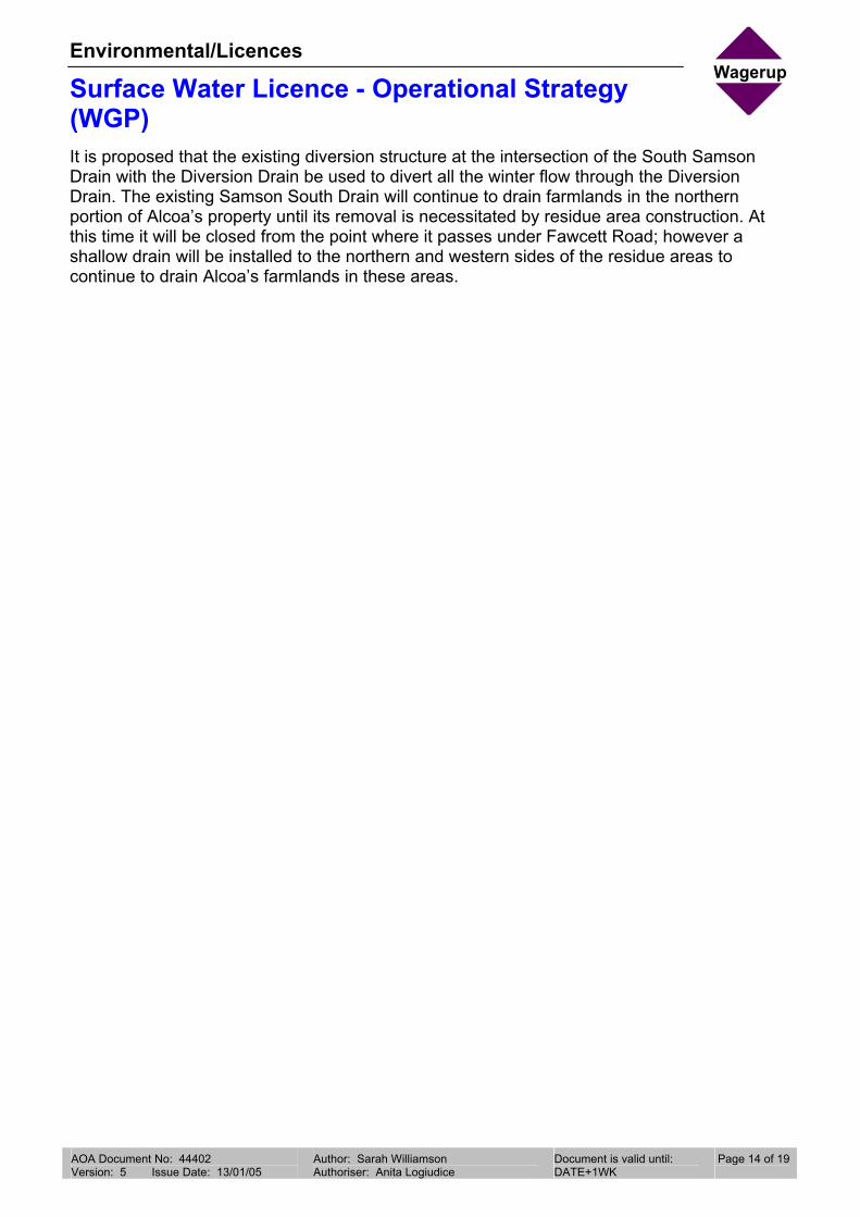
Environmental/Licences
Surface Water Licence - Operational Strategy (WGP)
Wagerup
AOA Document No: 44402 Version: 5 Issue Date: 13/01/05
Author: Sarah Williamson Authoriser: Anita Logiudice
Document is valid until: DATE+1WK /1234567890
Page 14 of 19
It is proposed that the existing diversion structure at the intersection of the South Samson Drain with the Diversion Drain be used to divert all the winter flow through the Diversion Drain. The existing Samson South Drain will continue to drain farmlands in the northern portion of Alcoa’s property until its removal is necessitated by residue area construction. At this time it will be closed from the point where it passes under Fawcett Road; however a shallow drain will be installed to the northern and western sides of the residue areas to continue to drain Alcoa’s farmlands in these areas.

Environmental/Licences
Surface Water Licence - Operational Strategy (WGP)
Wagerup
AOA Document No: 44402 Version: 5 Issue Date: 13/01/05
Author: Sarah Williamson Authoriser: Anita Logiudice
Document is valid until: DATE+1WK /1234567890
Page 15 of 19
4. Monitoring
4.1 Quantity The volume of water drawn by Alcoa from the various sources will be measured so as to gauge compliance with the operating strategy. Similarly the volume released downstream from diversion/storage points, including excess winter flow releases and environmental releases will be monitored. Table 2 summarises the location and frequency of such monitoring. Flow monitoring has been in place on a number of the streams within the vicinity of the refinery for many years. Figure 4 provides a summary of this monitoring data.
Flow monitoring
-5,000,000
10,000,00015,000,00020,000,00025,000,00030,000,00035,000,000
1982
1983
1984
1985
1986
1987
1988
1989
1990
1991
1992
1993
1994
1995
1996
1997
1998
1999
2000
2001
Year
Flow
(kl)
-
200
400
600
800
1,000
1,200
Ann
ual R
ainf
all (
mm
)Cooyah - SP12 Detn Pond - SP5 Nth Yallup - SP1
South Samson Drain - SP10 Samson Diversion - SP6 Rain
Figure 4 Summary of stream flow monitoring
4.2 Quality Surface water quality monitoring is conducted at station SP12 (see Figure 1) in accordance with the monitoring parameters and frequency set within the Wagerup Refinery’s DoE licence. Table 3 below outlines the frequency of monitoring, and parameters measured at each site.
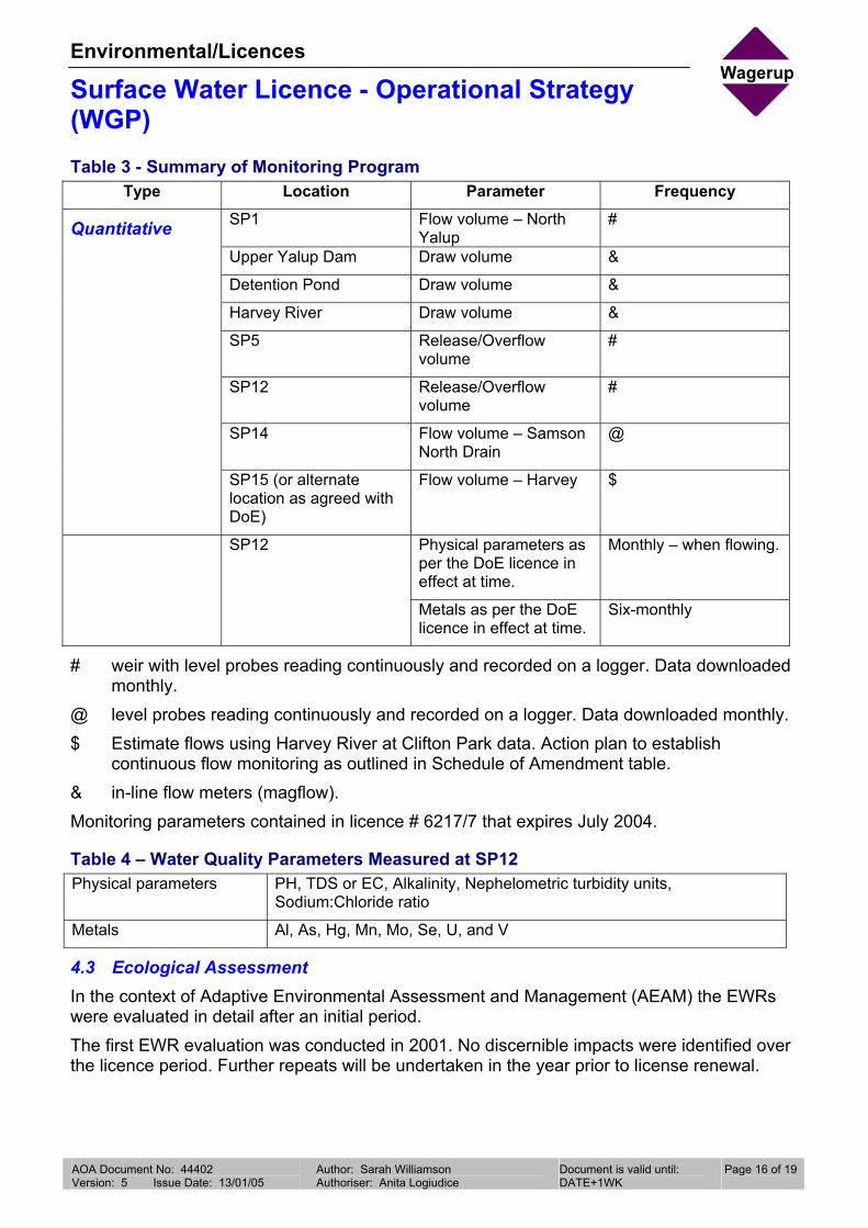
Environmental/Licences
Surface Water Licence - Operational Strategy (WGP)
Wagerup
AOA Document No: 44402 Version: 5 Issue Date: 13/01/05
Author: Sarah Williamson Authoriser: Anita Logiudice
Document is valid until: DATE+1WK /1234567890
Page 16 of 19
Table 3 - Summary of Monitoring Program Type Location Parameter Frequency
SP1 Flow volume – North Yalup
#
Upper Yalup Dam Draw volume &
Detention Pond Draw volume &
Harvey River Draw volume &
SP5 Release/Overflow volume
#
SP12 Release/Overflow volume
#
SP14 Flow volume – Samson North Drain
@
Quantitative
SP15 (or alternate location as agreed with DoE)
Flow volume – Harvey $
Physical parameters as per the DoE licence in effect at time.
Monthly – when flowing. SP12
Metals as per the DoE licence in effect at time.
Six-monthly
# weir with level probes reading continuously and recorded on a logger. Data downloaded monthly.
@ level probes reading continuously and recorded on a logger. Data downloaded monthly. $ Estimate flows using Harvey River at Clifton Park data. Action plan to establish
continuous flow monitoring as outlined in Schedule of Amendment table. & in-line flow meters (magflow). Monitoring parameters contained in licence # 6217/7 that expires July 2004.
Table 4 – Water Quality Parameters Measured at SP12 Physical parameters PH, TDS or EC, Alkalinity, Nephelometric turbidity units,
Sodium:Chloride ratio
Metals Al, As, Hg, Mn, Mo, Se, U, and V
4.3 Ecological Assessment In the context of Adaptive Environmental Assessment and Management (AEAM) the EWRs were evaluated in detail after an initial period. The first EWR evaluation was conducted in 2001. No discernible impacts were identified over the licence period. Further repeats will be undertaken in the year prior to license renewal.

Environmental/Licences
Surface Water Licence - Operational Strategy (WGP)
Wagerup
AOA Document No: 44402 Version: 5 Issue Date: 13/01/05
Author: Sarah Williamson Authoriser: Anita Logiudice
Document is valid until: DATE+1WK /1234567890
Page 17 of 19
5. Water Efficiency
Alcoa will commit to developing a water efficiency plan outlining consumption, water auditing and target reductions in water use. It should be noted that the quantities of water required to sustain a refining capacity of 3.3 Mtpa, are only marginally greater than the total requirement forecast in the original ERMP for a refining capacity of 2.0Mtpa. The water circuit is closed with the only losses being from evaporation and that tied up with the residue deposition. Considerable water efficiencies have already been obtained through: (i) The introduction of dry residue storage practices. (ii) Operating the residue system with the smallest possible alkaline water surface, reducing
the potential for evaporative losses. (iii) Water conservation initiatives and substitution within the refinery to conserve potable
quality water.

Environmental/Licences
Surface Water Licence - Operational Strategy (WGP)
Wagerup
AOA Document No: 44402 Version: 5 Issue Date: 13/01/05
Author: Sarah Williamson Authoriser: Anita Logiudice
Document is valid until: DATE+1WK /1234567890
Page 18 of 19
6. Communication
The DoE and Alcoa acknowledge the benefits and need for maintaining regular communication. Both parties commit to meet at least once a year, in May, to discuss surface water use and allocation issues. As part of water resource management in the southwest, the DoE recognise the Alcoa Wagerup Refinery as a major stakeholder, and aim to establish and maintain an effective working relationship with Alcoa.

Environmental/Licences
Surface Water Licence - Operational Strategy (WGP)
Wagerup
AOA Document No: 44402 Version: 5 Issue Date: 13/01/05
Author: Sarah Williamson Authoriser: Anita Logiudice
Document is valid until: DATE+1WK /1234567890
Page 19 of 19
7. Schedule Of Amendments
Date Amendment Details Signatories
June 2002 Licenced allocation for Black Tom Brook reduced and Samson South removed. New licence for abstraction from Harvey River.
March 2003 Interim licences replaced by Harvey River licence. Alan Cook and Katie Gwynne
March 2004 Introduction amended to outline current licences
Amended to include licence condition stating water can only be pumped from the Harvey from May – October.
Updated Water Balance diagram
Annual reporting against the requirements of the operational strategy will be incorporated into Alcoa’s Impacts on waters Report.
Section 3.1 Water Allocation changed to reflect allocation changes under a production capacity of 2.4Mtpa and 3.3 Mtpa.
Updated DEWCP and WRC to DoE
Alan Cook and Richard Bailey.
January 2005 Action Plan to cover delay in establishing continuous monitoring station on Harvey Drain at SP15 (Bristol Rd) or other more suitable location:
a. For 2004 Annual report estimate flow below pump station using Harvey Drain at Clifton Park (Win Site ID# 16257) data.
b. Install level probe at Bristol Road or other agreed location to measure flows in winter 2005
c. Install permanent flow monitoring station downstream of pump station at agreed location by 31 December 2005 (subject to DoE and Water Corporation approval).
Alan Cook and Anita Logiudice

Environmental Review and Management Programme Wagerup Refinery Unit 3 May 2005 Alcoa World Alumina Australia Page 486
Ref: ERMP Wagerup Unit 3 May 05 ENVIRON
10.4 SPILL MANAGEMENT PLAN

SPILL MANAGEMENT PLAN
Wagerup Refinery Unit 3 for
Alcoa World Alumina Australia ENVIRON Australia Pty Ltd Suite 3, Level 2 200 Adelaide Terrace East Perth, Western Australia 6004 Telephone: +618 9225 5199 Ref: Spill Management Plan v0 April 2005 Facsimile: +618 9225 5155

Spill Management Plan Wagerup Refinery Unit 3 19 April 2005 for Alcoa World Alumina Page i
Ref: Spill Management Plan v0 19 April.doc 2005 ENVIRON
TABLE OF CONTENTS
Page No.
1. INTRODUCTION.................................................................................................................... 1
2. FUNCTION .............................................................................................................................. 2
3. RELATED DOCUMENTS ..................................................................................................... 2
4. PROCEDURES........................................................................................................................ 3
Table 1. Indicative Release Prevention, Control and Countermeasure Procedures for the Wagerup Refinery Unit Three ........................................................................................................................... 5

Spill Management Plan Wagerup Refinery Unit 3 19 April 2005 for Alcoa World Alumina Page 1
Ref: Spill Management Plan v0 19 April.doc 2005 ENVIRON
SPILL MANAGEMENT PLAN Wagerup Refinery Unit 3
1. INTRODUCTION Alcoa’s Wagerup alumina refinery and its associated bauxite residue drying areas (RDAs) are located 120 kilometres south of Perth, two kilometres north of Yarloop and approximately seven kilometres south of Waroona. The refinery is located close to the foot of the Darling Scarp and is separated from the RDAs by the South West Highway and the Perth-Bunbury railway line. The refinery produces alumina from bauxite mined at the Willowdale mine site, using the Bayer process.
Alcoa proposes to expand its existing Wagerup alumina refinery through completing the construction of a third production unit (the Proposal). Construction of the third production unit will increase production to a total of approximately 4.7 Mtpa. An Environmental Review and Management Program (ERMP) has been prepared and submitted to the Environmental Protection Authority (EPA) for assessment under Part IV of the Environmental Protection Act 1986. This Spill Management Plan forms part of the ERMP and is included as an Appendix to the document. Wagerup Refinery extracts alumina from bauxite through a process involving numerous tanks, vessels, pumps and interconnecting pipes. After the proposed expansion there will be an increased volume of alkaline process liquor circulated throughout the Bayer circuit. Although solutions of sodium hydroxide are by far the biggest volume of process chemical, there are also significant quantities of acid, flocculant, distillate, cooling tower treatment chemicals, and other special additives. Key Risks: Materials such as caustic soda which if spilt can become mobile in the subsurface and may contaminate large areas of soil and groundwater if not contained. In addition hydrocarbons and other chemicals used in the process, and process liquors may also pollute soils and/or groundwater and surface water if released to the environment. Failure of containment vessels, faulty pipework, operational error, poor maintenance and housekeeping, power failures, cracks in concrete surfaces and failure of secondary containment areas (e.g. bunding) are some of the ways spills and leaks may occur. Development of the Proposal will result in an increase in the volumes of process chemicals, materials and liquors in the refinery system, and an increase in the requirement for containment vessels and pipework, thereby increasing the potential risk of leaks and spills. It is therefore important that appropriate spill prevention and control measures are implemented. The strategy for controlling chemicals is based on a hierarchy of control which takes account of the requirements of the Department of Environment (DoE) and Department of Industry and Resources (DoIR) containment expectations as described in the licence, and the Dangerous Goods Safety Act 2004 and associated Regulations.
Spill Management Plan Wagerup Refinery Unit 3 19 April 2005 for Alcoa World Alumina Page 2
Ref: Spill Management Plan v0 19 April.doc 2005 ENVIRON
The hierarchy of control is; Primary Controls
• Process control; level alarms, process control logic; • Maintenance of equipment and instruments; • Inspections of tanks (flat bottom tank inspections, non destructive testing, pipeline thickness
testing). Secondary Controls
• Bunds; • Sumps and pumps.
Tertiary Controls
• Concrete and bitumen pavement and drains; • Stormwater drainage system; • Emergency Response.
These operational controls are described in more detail in section 4 (Procedures) of this report. 2. FUNCTION This Spill Management Plan has been prepared for the Proposal. The plan is designed to reference relevant procedures in Wagerup operations’ existing Environmental Management System (EMS) and outline any additional controls and procedures necessary to minimise the hazards to human health and the environment from releases of toxic and hazardous substances to the soil, surface waters and groundwater. This Spill Management Plan will be reviewed and updated at a minimum of once every three years, or if changes to the process occur or major new projects at the refinery are implemented. 3. RELATED DOCUMENTS This Spill Management Plan for the Proposal should be applied in the context of the existing Environmental Management Manual for Wagerup (Document No. 32600). This manual is a key document of the Wagerup Environmental Management System and the main reference document on environmental policy and principles, team structures, standards and statutory requirements, identification of environmental aspects and associated planning, management systems, procedures and environmental monitoring. Spill prevention and control procedures for the existing Wagerup Refinery and Bunbury Port Operations are provided in the Release Prevention, Control and Countermeasure (RPCC) Plan (Document No. 38833). This Spill Management Plan for the Proposal makes reference to the RPCC
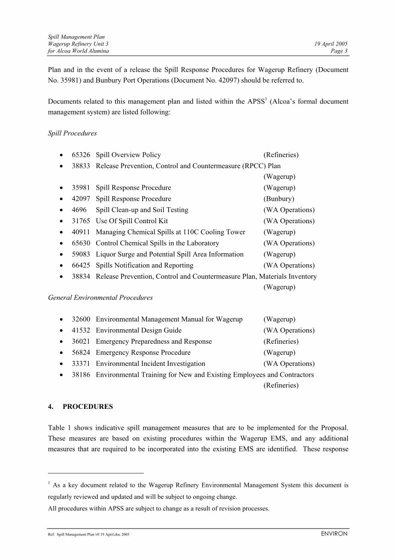
Spill Management Plan Wagerup Refinery Unit 3 19 April 2005 for Alcoa World Alumina Page 3
Ref: Spill Management Plan v0 19 April.doc 2005 ENVIRON
Plan and in the event of a release the Spill Response Procedures for Wagerup Refinery (Document No. 35981) and Bunbury Port Operations (Document No. 42097) should be referred to. Documents related to this management plan and listed within the APSS1 (Alcoa’s formal document management system) are listed following: Spill Procedures
• 65326 Spill Overview Policy (Refineries) • 38833 Release Prevention, Control and Countermeasure (RPCC) Plan
(Wagerup) • 35981 Spill Response Procedure (Wagerup) • 42097 Spill Response Procedure (Bunbury) • 4696 Spill Clean-up and Soil Testing (WA Operations) • 31765 Use Of Spill Control Kit (WA Operations) • 40911 Managing Chemical Spills at 110C Cooling Tower (Wagerup) • 65630 Control Chemical Spills in the Laboratory (WA Operations) • 59083 Liquor Surge and Potential Spill Area Information (Wagerup) • 66425 Spills Notification and Reporting (WA Operations) • 38834 Release Prevention, Control and Countermeasure Plan, Materials Inventory
(Wagerup) General Environmental Procedures
• 32600 Environmental Management Manual for Wagerup (Wagerup) • 41532 Environmental Design Guide (WA Operations) • 36021 Emergency Preparedness and Response (Refineries) • 56824 Emergency Response Procedure (Wagerup) • 33371 Environmental Incident Investigation (WA Operations) • 38186 Environmental Training for New and Existing Employees and Contractors
(Refineries) 4. PROCEDURES Table 1 shows indicative spill management measures that are to be implemented for the Proposal. These measures are based on existing procedures within the Wagerup EMS, and any additional measures that are required to be incorporated into the existing EMS are identified. These response
1 As a key document related to the Wagerup Refinery Environmental Management System this document is
regularly reviewed and updated and will be subject to ongoing change.
All procedures within APSS are subject to change as a result of revision processes.

Spill Management Plan Wagerup Refinery Unit 3 19 April 2005 for Alcoa World Alumina Page 4
Ref: Spill Management Plan v0 19 April.doc 2005 ENVIRON
actions are reviewed periodically, following significant events and as process changes are made, consequently the actions listed are to be considered indicative only. Atmospheric releases (e.g. dust, gaseous emissions, vapours) are to be managed in accordance with the Air Quality Management Plan prepared for the Proposal. (Refer to the RPCC Plan for facility descriptions, the refinery process, materials used on site and the stormwater system).

Spill Management Plan Wagerup Refinery Unit 3 19 April 2005 for Alcoa World Alumina Page 5
Ref: Spill Management Plan v0 19 April.doc 2005 ENVIRON
Table 1. Indicative Release Prevention, Control and Countermeasure Procedures for the Proposal
What How Procedure Reference Who When Performance Indicator RELEASE PREVENTION Objective 1. Identify any changes or increase in the risk of spills with the Wagerup Unit 3 expansion and put in place appropriate measures to minimise these risks.
Action 1.1 Assessment of the risk of spills for the expanded Refinery will be determined through using the “Aspects Impacts Identification and Evaluation Procedure” as follows: 1. Form a team to assess the environmental consequences
of the expanded operations. 2. Define the process for the operation of the OC area (e.g.
Normal Operations, Start Up and Shut Down, Emergency Stops, Upset Conditions and Maintenance Operations).
3. Become familiar with process. 4. Identify Aspect and Impacts. 5. Identify existing engineering and procedural controls. 6. Undertake the risk assessment with and without control
measures, identifying ‘likelihood’ and ‘consequence’ of the potential impacts. All risks ‘Medium’ are considered ‘significant’ environmental impacts. Those risks which are not considered acceptable (i.e. risk not as low as reasonably possible (ALARP)) must have action plans to reduce the risk to ALARP.
7. Formulate an Aspects and Impacts Register and link to Action Plans.
Put in place appropriate controls through Design, Operation, Maintenance and Training/Awareness measures outlined in
41716 ‘Identify and Evaluate Environmental Aspects and Impacts’
Refer to document 41716 for specific Responsibilities.
Prior to construction of the expansion, on commissioning and as required (e.g. in the event of a significant new project or process change).
Aspects Impacts Register up to date for expanded refinery. Current Action Plans are being implemented.

Spill Management Plan Wagerup Refinery Unit 3 19 April 2005 for Alcoa World Alumina Page 6
Ref: Spill Management Plan v0 19 April.doc 2005 ENVIRON
What How Procedure Reference Who When Performance Indicator Action 2.
Design: Objective 2. Design chemical/process material storage, handling and transfer infrastructure to minimise risk of spills.
Action 2.1 Design the expanded Refinery in accordance with: 1. Secondary Containment Design Guidelines For
Dangerous Goods (Document 5076). 2. Corporate Mandated Standard for the Use of
Underground Storage Tanks (Document 5541). 3. AS 1940 Storage and handling of flammable and
combustible liquids. 4. AS 3780 The storage and handling of corrosive
substances. Action 2.2 Conduct risk assessment to analyse operational and maintenance conditions that could result in accidental release scenarios. Action 2.3 Analysis the potential existing contamination of ‘brown-field’ expansion. Action 2.4 Design primary and secondary containment systems to eliminate potential of uncontrolled spillage to the environment. Release of contaminated liquor outside the controlled environment is not acceptable. Action 2.5
41532 ‘Environmental Design Guide’ 5076 ‘Secondary Containment Design Guidelines For Dangerous Goods’ 5541 ‘Corporate Mandated Standard for the Use of Underground Storage Tanks’
Engineering Department
During design and construction.
No release of process liquors/contaminated water outside the controlled Refinery environment.

Spill Management Plan Wagerup Refinery Unit 3 19 April 2005 for Alcoa World Alumina Page 7
Ref: Spill Management Plan v0 19 April.doc 2005 ENVIRON
What How Procedure Reference Who When Performance Indicator Ensure stormwater drainage systems are not used for process water. Action 2.6 Install process fluid pipelines above-ground. Action 2.7 Design to ensure drain down pipes, valves and future maintenance for caustic fluids are contained within the confines of the steel containment system. Action 2.8 Ensure flat bottom tanks have membrane protection. Design tanks to minimise potential for corrosion. Action 2.9 Install appropriate leak detection and spill warning systems on expanded refinery.
Operation: Objective 3. All practicable measures will be taken to ensure that process materials are contained within designed primary and secondary containment facilities such as tank,
Action 3.1 Maintain good housekeeping standards and use appropriate housekeeping procedures where required.
Action 3.2 Ensure leak detection and spill warning systems are kept in working order.
Action 3.3 Update operating procedures for expanded refinery and implement.
Refer to Housekeeping and Environmental Inspections procedures (eg. for:
• Workshop (45211); • Fitting Workshop
(45213) • Fabrication Workshop
(45215) • Pump Factory (67530) • Machining Workshop
Area Co-coordinators
Ongoing during operations.
No release of process liquors/contaminated water outside the controlled Refinery environment.

Spill Management Plan Wagerup Refinery Unit 3 19 April 2005 for Alcoa World Alumina Page 8
Ref: Spill Management Plan v0 19 April.doc 2005 ENVIRON
What How Procedure Reference Who When Performance Indicator pipework, drains, sumps, concrete slabs and bunds.
Action 3.4 Ensure off-loading of fuel, sulphuric acid, lime, flocculant and fuel is undertaken on a bunded area where spills can be contained and treated appropriately. Action 3.5 Store and manage drums and containers whose contents have the potential to impact on the environment, in accordance with:
− Drum Management Guidelines (5146); − Oils and Chemicals Containment (5100); − Corporate Environmental Policy Interpretation
(36757). Action 3.6 All tanks are to be above-ground and stored in accordance with the Dangerous Goods Regulations 1992 (unless they are exempt, e.g. process vessels). Action 3.7 Construct any new surface water containments at the Residue Drying Area with PVC liners.
(45214) • Valve Factory (67528) • Spool Factory (67529). • Drum Management
Guidelines (5146); • Oils and Chemicals
Containment (5100); • Corporate
Environmental Policy Interpretation (36757).
Maintenance: Objective 4. Ensure adequate maintenance is continued to minimise
Action 4.1 Implement inspection and maintenance procedures such as: • structural tank inspections; • concrete inspections; and • general maintenance.
All relevant inspection and maintenance procedures. ‘Ultrasonic Condition
Area co-coordinators
Ongoing during operations.
No release of process liquors/contaminated water outside the controlled Refinery environment.

Spill Management Plan Wagerup Refinery Unit 3 19 April 2005 for Alcoa World Alumina Page 9
Ref: Spill Management Plan v0 19 April.doc 2005 ENVIRON
What How Procedure Reference Who When Performance Indicator risk of leaks and spills.
Action 4.2 Update the FMMS system to include Inspection Schedules for new equipment and tanks associated with the Wagerup Unit 3 Project. Action 4.3 Periodically undertake ultrasonic monitoring of the sand to lake pipelines to check for pipe wear. Action 4.4 Check cooling water return lines from the Cooling Pond for leaks, on a monthly basis
Monitoring Sand to Lake Lines Thickness Testing’ (5313)
Training and Awareness: Objective 5 All Alcoa workforce and contractors are to be made aware of their legal obligations with regards to spill prevention, control and countermeasures.
Action 5.1 All new employees and contractors must undergo an induction to provide overall awareness of the safety and environmental issues on site, including Emergency Spill Response training.
‘Environmental Training for New and Existing Employees and Contractors’ (38186) ‘Emergency Preparedness & Response’ (36021)
All personnel. During construction and operation.
Training records indicate all Alcoa workforce and contractors have an understanding of the basic requirements of spill prevention, control and countermeasures.
Objective 6. Ensure all potentially hazardous materials involved in the upgraded refinery are
Action 6.1 Update RPCC Materials Inventory for Expanded Refinery.
‘RPCC Materials Inventory’ (38834)
Refer to document 38834 for specific responsibilities.
Prior to commissioning.
RPCC Materials Inventory up to date for Expanded Refinery
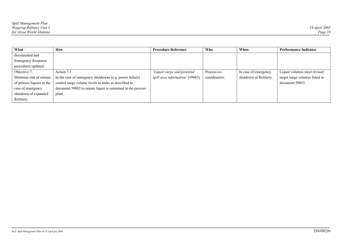
Spill Management Plan Wagerup Refinery Unit 3 19 April 2005 for Alcoa World Alumina Page 10
Ref: Spill Management Plan v0 19 April.doc 2005 ENVIRON
What How Procedure Reference Who When Performance Indicator documented and Emergency Response procedures updated. Objective 7. Minimise risk of release of process liquors in the case of emergency shutdown of expanded Refinery.
Action 7.1 In the case of emergency shutdowns (e.g. power failure) control surge volume levels in tanks as described in document 59083 to ensure liquor is contained in the process plant.
‘Liquor surge and potential spill area information’ (59083)
Process co-coordinators.
In case of emergency shutdown of Refinery.
Liquor volumes meet revised target surge volumes listed in document 59053.

Spill Management Plan Wagerup Refinery Unit 3 19 April 2005 for Alcoa World Alumina Page 11
Ref: Spill Management Plan v0 19 April.doc 2005 ENVIRON
What How Procedure Reference Who When Performance Indicator RELEASE CONTROL Objective 8. Contain and clean-up leaks and spills to prevent harm to persons, environment or property.
Action 8.1 Follow the procedure in document 35981: 1. Assess the situation (and risk to health and the
environment). 2. Protect people (e.g. if required evacuate, warn others,
request assistance, undertake initial temporary control); 3. Prevent further spillage and contain spill if safe to do so
(if not safe Emergency personnel to bring situation under control).
4. Notify the appropriate people (Area Co-ordinator immediately; Area Co-ordinator to notify Supervisor/Manager by next working day. Refer to document 35981 for reporting of major and extreme spills).
5. Clean up the spill and dispose of spillage and waste appropriately if safe to do so (Refer to 31765 ‘Use of Spill Control Kit’). If not safe to do so, Emergency personnel to clean up and properly dispose of spill.
6. Follow-up by monitoring environmental impacts, reviewing responses to spill, completing reporting and modifying practices to prevent a re-occurrence.
‘Spill Response Overview and Policy’ (65326) ‘Spill Response Procedure’ (35981)
All staff.
As soon as spill observed.
Details of all spills documented in incident reports. Corrective actions implemented within an appropriate time frame.
Objective 9. Contain and clean-up leaks and spills using appropriate Spill Kits.
Action 9.1 Use procedure ‘Use of Spill Control Kit’ (document 31765) to clean up spills if appropriate and safe to do so, wearing correct PPE:
‘Use of Spill Control Kit’(31765)
Employees that have been trained in the use of Spill Kits as defined in document 31765
As soon as spill observed after necessary safety and environmental precautions taken (see
All spills cleaned up promptly and disposed of appropriately.

Spill Management Plan Wagerup Refinery Unit 3 19 April 2005 for Alcoa World Alumina Page 12
Ref: Spill Management Plan v0 19 April.doc 2005 ENVIRON
What How Procedure Reference Who When Performance Indicator 1. Barricade corridors if necessary. 2. Switch off electricity if necessary. 3. Remove portable furniture or equipment from the spill
area if safe to do so. 4. Use puddle python to stop the spill spreading. 5. Place one or more pillows directly on the spill and
press into the spill. 6. Place saturated pillows and python into plastic bags. 7. Label the contents. 8. Store in a metal bin prior to disposal. Method of
disposal must be decided by laboratory supervisor, and/or the Environmental, Health and Safety Department.
9. Notify supervisor of spill incident. 10. Report to the service coordinator to replace used items
from spill kit.
Alumina spilt during train loading will be vacuumed and wagons washed before leaving site.
document 35981).
Objective 10. Clean up spills to soils and confirm adequacy of clean up with soil tests.
Action 10.1 Follow the clean up and testing procedure in document 4696: 1. Identify chemical and criteria level. 2. Determine method of testing for compliance with
criteria. 3. Identify area and depth of contamination. 4. Consider if the appropriate permits have been obtained,
if problems of structures in close proximity and if occupational hazards exist (check PPE requirements).
‘Spill Clean-up and Soil Testing’ (4696)
Refer to document 4696 for responsibility for clean up of different chemicals.
As soon as spill observed.
Contamination levels in remaining soil below ‘Maximum Allowable Contamination Level Guidelines’.

Spill Management Plan Wagerup Refinery Unit 3 19 April 2005 for Alcoa World Alumina Page 13
Ref: Spill Management Plan v0 19 April.doc 2005 ENVIRON
What How Procedure Reference Who When Performance Indicator 5. Contact Environmental, Health and Safety Department
for advice on removal/remediation of contaminated soil. 6. Remove identified contamination if advised by
Environmental, Health and Safety Department. 7. Test remaining soil to see if within criteria outlined in
‘Maximum Allowable Contamination Level Guidelines’. 8. Environmental, Health and Safety Department to
determine long term remediation if required. 9. Backfill with clay and top-dress.
Objective 11. Clean up any spills within the 110C Cooling Tower chemical containment bunds to prevent harm to persons or the environment.
Action 11.1 Follow the procedure in document 40911: 1. On discovery of a chemical spill the person/controller
should remove themselves from the immediate area, if the leak poses a serious risk and advise control room immediately.
2. LCN Controller should notify Security request the area be secured: a. Use barricade tape; b. Ensure bund drain shut; c. Limit spillage to the bund.
3. Determine nature of spillage. 4. Isolate spill/leak. 5. Notify appropriate person. 6. Chemical supplier/contractor to evaluate spill and
recovery, disposal, neutralising options. 7. Ensure selected clean-up method is undertaken by the
chemical supplier/contractor in a safe manner.
‘Managing Chemical Spills at 110C Cooling Tower’ (40911)
Refer to document 40911 for specific responsibilities.
As soon as spill observed.
Details of all spills documented in incident reports. Corrective actions implemented within an appropriate time frame.

Spill Management Plan Wagerup Refinery Unit 3 19 April 2005 for Alcoa World Alumina Page 14
Ref: Spill Management Plan v0 19 April.doc 2005 ENVIRON
What How Procedure Reference Who When Performance Indicator Objective 12. Ensure chemical spills in the laboratory are cleaned up in a safe and environmentally responsible manner.
Action 12.1 Use procedure in document 65630 using correct PPE to clean up laboratory chemical spills: 1. Vacate the area of the spillage immediately. 2. Barricade the area to avoid access from other personnel. 3. Alert all laboratory staff that a spill has occurred. 4. Ascertain nature of the spill without any risk to yourself
or other personnel. 5. If you are unsure of the nature of the spill or if fumes are
being generated call the Emergency Response Crew on 222 and provide full details regarding location and possible nature of the spill, and evacuate building if copious noxious fumes are being generated.
6. If the spill is minor, you know the nature of the spill and no fumes are being generated then clean up the spill using a spill kit as outlined in document 65630.
7. Consult Environmental Services regarding the disposal of the spent absorbent. Approved waste contractors are available that can arrange the final disposal offsite or advise if the wastes may be safely disposed of to the RDA.
‘Control Chemical Spills in the Laboratory’ (65630)
All laboratory personnel.
As soon as spill is observed.
Details of all spills documented in incident reports. Corrective actions implemented within an appropriate time frame.

Spill Management Plan Wagerup Refinery Unit 3 19 April 2005 for Alcoa World Alumina Page 15
Ref: Spill Management Plan v0 19 April.doc 2005 ENVIRON
What How Procedure Reference Who When Performance Indicator RELEASE COUNTERMEASURES Objective 13. Report spills to appropriate person.
Action 13.1 The Director of WA Operations must be advised of spills larger than 2 kL. The escalation of notification should be as follows: 1. Supervisor for the area. 2. Operating Centre Manager. 3. Environmental, Health and Safety Manager (who is
responsible for coordinating appropriate government notifications).
4. Manufacturing Manager and/or the Refinery Manager; 5. Director WA Operations.
‘Spills Notification and Reporting’ (66425)
All personnel. Spills > 2 kL which remain in a bund or overflow the bunded area onto sealed ground to be reported to Director WA Operations within 8 hours. Spills > 2 kL which contact bare soil to be reported to Director WA Operations immediately.
Incident report indicates correct personnel notified within required time.
Objective 14. Complete an Incident Investigation and Report for the spill
Action 14.1 Raise an Environmental Incident Report as soon as practicable after the spill, using the EHS Incident Management System. • Determine incident investigation level. • Determine team composition. • Gather information. • Data analysis. • Determine root causes. • Identify possible corrective actions and priorities. • Document findings. • Follow up on recommendations to ensure completed. • Sign off.
‘(EHS) Environmental Incident Investigation’ (33371)
Investigation co-coordinator
As soon as practicable after spill.
Incident investigations and reports available for each spill. Corrective actions implemented within an appropriate time frame.

Spill Management Plan Wagerup Refinery Unit 3 19 April 2005 for Alcoa World Alumina Page 16
Ref: Spill Management Plan v0 19 April.doc 2005 ENVIRON
What How Procedure Reference Who When Performance Indicator
Objective 15. Monitor and report losses from the system as required for the National Pollution Inventory
Action 15.1 Estimate of the quantity of spilt Bayer Liquor for use in the National Pollution Inventory (NPI) annual report using the Environmental Incident (EI) System and calculation of the leakage of spilt material from the storm water system as outlined in document 46571. Specific instructions for calculations are outlined in this document.
NPI Bayer Liquor Spill Quantity Estimate (46571)
Environmental, Health and Safety Department
Annually (by September)
Monitoring records indicate compliance with DoE licensed emissions.
Note: Procedures are subject to review and change as part of ongoing operations.