1.0 INTRODUCTION 2.0 REFERENCES
19
Golder Associates Pty Ltd Level 8, 40 Mount Street, North Sydney, New South Wales 2060, Australia T: +61 2 9478 3900 F: +61 2 9478 3901 A.B.N. 64 006 107 857 Golder and the G logo are trademarks of Golder Associates Corporation golder.com 28 November 2019 Reference No. 19125312-002-L-Rev1 Alain Pavelic Built Pty Ltd Level 7/343 George St, Sydney, NSW 2000 LIVERPOOL CIVIC PLACE PRELIMINARY GEOTECHNICAL ASSESSMENT Dear Alain, 1.0 INTRODUCTION Built Pty Ltd (Built) has engaged Golder Associates Pty Ltd (Golder) to carry out a preliminary geotechnical assessment for the Liverpool Civic Place project (the site). We understand that this assessment which involves two-dimensional finite element modelling will be used to inform the structural design of retention for bulk excavation works for the site in an early works contract. The work is carried out in accordance with our proposal in an email sent to you on 5 November 2019 and your approval to proceed in an email dated 6 November 2019. In this revision, we have considered a bulk excavation level at RL +10.35 m AHD as instructed. 2.0 REFERENCES The following documents were referred to in order to carry out the preliminary modelling presented in this report. Geotechnical and Environmental Investigation Report (ref.: 19125312-001-Rev1) by Golder dated 29 August 2019; Structural Drawings for adjacent buildings at 300 Macquarie St (ref.: 2012-176/C01-C04 and S01-S06) by Burgess, Arnott and Grava dated March 2013; Construction Staging Plan (ref.: SK-C-0004[D]) by Built received on 6 November 2019; and Structural Drawings (ref.: SK-C-0002-0006) by fmjt dated 31 July 2019.
Transcript of 1.0 INTRODUCTION 2.0 REFERENCES
Golder Associates Pty Ltd
Level 8, 40 Mount Street, North Sydney, New South Wales 2060, Australia
T: +61 2 9478 3900 F: +61 2 9478 3901
A.B.N. 64 006 107 857
Golder and the G logo are trademarks of Golder Associates Corporation golder.com
28 November 2019 Reference No. 19125312-002-L-Rev1
Alain Pavelic
Built Pty Ltd
Level 7/343 George St,
Sydney, NSW 2000
LIVERPOOL CIVIC PLACE
PRELIMINARY GEOTECHNICAL ASSESSMENT
Dear Alain,
1.0 INTRODUCTION
Built Pty Ltd (Built) has engaged Golder Associates Pty Ltd (Golder) to carry out a preliminary geotechnical
assessment for the Liverpool Civic Place project (the site). We understand that this assessment which
involves two-dimensional finite element modelling will be used to inform the structural design of retention for
bulk excavation works for the site in an early works contract. The work is carried out in accordance with our
proposal in an email sent to you on 5 November 2019 and your approval to proceed in an email dated 6
November 2019.
In this revision, we have considered a bulk excavation level at RL +10.35 m AHD as instructed.
2.0 REFERENCES
The following documents were referred to in order to carry out the preliminary modelling presented in this
report.
Geotechnical and Environmental Investigation Report (ref.: 19125312-001-Rev1) by Golder dated 29
August 2019;
Structural Drawings for adjacent buildings at 300 Macquarie St (ref.: 2012-176/C01-C04 and S01-S06)
by Burgess, Arnott and Grava dated March 2013;
Construction Staging Plan (ref.: SK-C-0004[D]) by Built received on 6 November 2019; and
Structural Drawings (ref.: SK-C-0002-0006) by fmjt dated 31 July 2019.
Alain Pavelic Reference No. 19125312-002-L-Rev1
Built Pty Ltd 28 November 2019
2
3.0 PROPOSED BULK EXCAVATION
The proposed mixed-use development is understood to consist of a three-level basement car park. Built have
informed us that the bulk excavation level (BEL) to be adopted is at RL+10.35 m AHD.
The existing ground level along the southern part of the site along the Terminus Street is approximately at
RL+26 m AHD, about 3 m higher than the northern side along the Scott Street (i.e. RL+23 m AHD). The
excavation depth for the site range between 15 m and 16 m below ground level (bgl).
The existing building in the vicinity with a basement is located to the north-west of the site. Based on the
drawings provided, the bulk excavation for this building is to RL+17.8 m AHD, approximately 7.5 m higher
than the proposed BEL.
The groundwater level measured in August 2019 is generally at RL+17.5 m AHD, approximately 7.2 m higher
than the proposed BEL. However, an exception was the water level measured in BH304 at RL+15 m AHD.
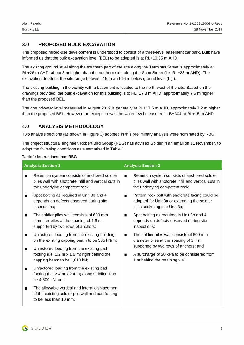
4.0 ANALYSIS METHODOLOGY
Two analysis sections (as shown in Figure 1) adopted in this preliminary analysis were nominated by RBG.
The project structural engineer, Robert Bird Group (RBG) has advised Golder in an email on 11 November, to
adopt the following conditions as summarised in Table 1.
Table 1: Instructions from RBG
Analysis Section 1 Analysis Section 2
Retention system consists of anchored soldier
piles wall with shotcrete infill and vertical cuts in
the underlying competent rock;
Spot bolting as required in Unit 3b and 4
depends on defects observed during site
inspections;
The soldier piles wall consists of 600 mm
diameter piles at the spacing of 1.5 m
supported by two rows of anchors;
Unfactored loading from the existing building
on the existing capping beam to be 335 kN/m;
Unfactored loading from the existing pad
footing (i.e. 1.2 m x 1.6 m) right behind the
capping beam to be 1,810 kN;
Unfactored loading from the existing pad
footing (i.e. 2.4 m x 2.4 m) along Gridline D to
be 4,600 kN; and
The allowable vertical and lateral displacement
of the existing soldier pile wall and pad footing
to be less than 10 mm.
Retention system consists of anchored soldier
piles wall with shotcrete infill and vertical cuts in
the underlying competent rock;
Pattern rock bolt with shotcrete facing could be
adopted for Unit 3a or extending the soldier
piles socketing into Unit 3b;
Spot bolting as required in Unit 3b and 4
depends on defects observed during site
inspections;
The soldier piles wall consists of 600 mm
diameter piles at the spacing of 2.4 m
supported by two rows of anchors; and
A surcharge of 20 kPa to be considered from
1 m behind the retaining wall.
Alain Pavelic Reference No. 19125312-002-L-Rev1
Built Pty Ltd 28 November 2019
3
The modelling is carried out using the commercially available finite element analysis software, PLAXIS 2D
2019. The construction sequence is idealised and simulated with the staged construction, generally as follows:
Generate in-situ stresses in the ground using Ko procedure;
The surcharge and retaining wall are wished-in-place in the model, where installation effects are not
considered;
Excavation is modelled by deactivating layers of soil in each stage (e.g. 2 m) and the pore-water
pressure distribution is calculated by steady-state analysis; and
Excavation is carried out to 0.5 m below the temporary ground anchors (if any), and the anchors are
installed by wished-in-place in the subsequent stage.
The ground models and geotechnical parameters adopted for the analysis will be based on our report
(ref.:19125312-001-R Rev 1) dated 29 August 2019, which are presented in the following sections in this
report.
We have assumed that all ground anchors provide temporary support only and the ground anchors will be de-
stressed as the construction of basement floor slabs progresses. The loads re-distributed to the constructed
floor slabs after destressing of ground anchors are to be modelled and considered in the detailed design
stage. The base and floor slabs of the basement structure will provide lateral support to the retention system
in the permanent condition.
Figure 1: Analysis Section Layout
Alain Pavelic Reference No. 19125312-002-L-Rev1
Built Pty Ltd 28 November 2019
4
5.0 GROUND MODEL
Table 2 presents the modelled ground profiles for each analysis section, which are inferred from the following
boreholes:
Analysis Section 1 – BH302 and BH303
Analysis Section 2 – BH305 and BH306
Based on the available borehole investigations, we anticipate that bedding of the rock units present on site will
be primarily horizontal. The defects in Unit 3a, 3b and 4 observed in the available boreholes has been
considered in the design parameters proposed in our geotechnical investigation report (ref.: 19125312-001-
Rev1).
The highly weathered material interbedded in Unit 3b is modelled with Unit 3a parameters. We have assumed
that any possible adverse jointing encountered in Unit 3a, 3b and 4 will be supported (e.g. pattern bolting, spot
bolting etc.) at each excavation stage. A 0.1 m thick horizontal joint (bedding plane) has been modelled in Unit
4, 0.3 m below the BEL, to investigate the possibility of excessive rock heave or fracturing of the floor rock
from stress concentration.
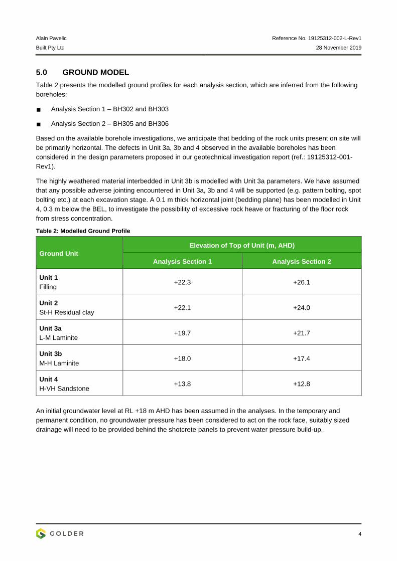
Table 2: Modelled Ground Profile
Ground Unit
Elevation of Top of Unit (m, AHD)
Analysis Section 1 Analysis Section 2
Unit 1
Filling +22.3 +26.1
Unit 2
St-H Residual clay +22.1 +24.0
Unit 3a
L-M Laminite +19.7 +21.7
Unit 3b
M-H Laminite +18.0 +17.4
Unit 4
H-VH Sandstone +13.8 +12.8
An initial groundwater level at RL +18 m AHD has been assumed in the analyses. In the temporary and
permanent condition, no groundwater pressure has been considered to act on the rock face, suitably sized
drainage will need to be provided behind the shotcrete panels to prevent water pressure build-up.
Alain Pavelic Reference No. 19125312-002-L-Rev1
Built Pty Ltd 28 November 2019
5
6.0 DESIGN PARAMETERS
The mechanical behaviour of the soils and rocks are modelled with Hardening Soil Model, which adopted the
Mohr-Coulomb failure criterion. The geotechnical parameters adopted are extracted from our geotechnical
investigation report (ref.: 19125312-001-Rev1) and summarised in Table 3.
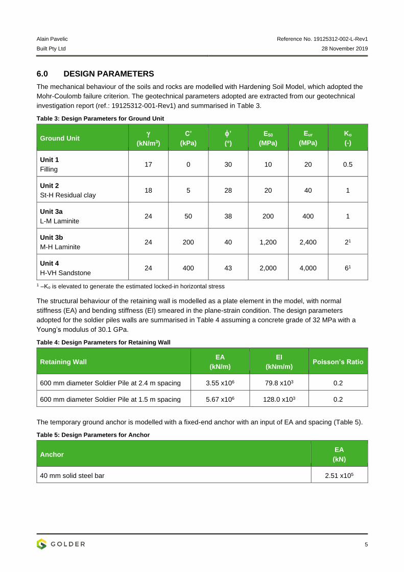
Table 3: Design Parameters for Ground Unit
Ground Unit
(kN/m3)
C’
(kPa)
’
(°)
E50
(MPa)
Eur
(MPa)
Ko
(-)
Unit 1
Filling 17 0 30 10 20 0.5
Unit 2
St-H Residual clay 18 5 28 20 40 1
Unit 3a
L-M Laminite 24 50 38 200 400 1
Unit 3b
M-H Laminite 24 200 40 1,200 2,400 21
Unit 4
H-VH Sandstone 24 400 43 2,000 4,000 61
1 –Ko is elevated to generate the estimated locked-in horizontal stress
The structural behaviour of the retaining wall is modelled as a plate element in the model, with normal
stiffness (EA) and bending stiffness (EI) smeared in the plane-strain condition. The design parameters
adopted for the soldier piles walls are summarised in Table 4 assuming a concrete grade of 32 MPa with a
Young’s modulus of 30.1 GPa.
Table 4: Design Parameters for Retaining Wall
Retaining Wall EA
(kN/m)
EI
(kNm/m) Poisson’s Ratio
600 mm diameter Soldier Pile at 2.4 m spacing 3.55 x10⁶ 79.8 x10³ 0.2
600 mm diameter Soldier Pile at 1.5 m spacing 5.67 x10⁶ 128.0 x10³ 0.2
The temporary ground anchor is modelled with a fixed-end anchor with an input of EA and spacing (Table 5).
Table 5: Design Parameters for Anchor
Anchor EA
(kN)
40 mm solid steel bar 2.51 x10⁵
Alain Pavelic Reference No. 19125312-002-L-Rev1
Built Pty Ltd 28 November 2019
6
7.0 RESULT OF ANALYSIS
7.1 Analysis Section 1 – Adjacent to Existing Building
Table 6 summarises the results computed in Analysis Section 1, for the proposed 600 mm diameter soldier
pile wall at 1.5 m spacing for each construction stage. The foundation loads from the adjacent building (as
provide by RBG) is considered as an equivalent infinite strip load in this plane strain analysis, using the
method by Williams and Waite (1993)1 as presented in CIRIA C760. The maximum wall displacement is
computed to be 8 mm.
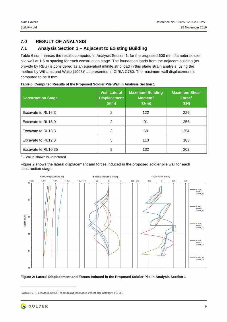
Table 6: Computed Results of the Proposed Soldier Pile Wall in Analysis Section 1
Construction Stage
Wall Lateral
Displacement
(mm)
Maximum Bending
Moment1
(kNm)
Maximum Shear
Force1
(kN)
Excavate to RL16.3 2 122 229
Excavate to RL15.0 2 91 256
Excavate to RL13.8 3 69 254
Excavate to RL12.3 5 113 183
Excavate to RL10.35 8 132 202
1 – Value shown is unfactored.
Figure 2 shows the lateral displacement and forces induced in the proposed soldier pile wall for each construction stage.
Figure 2: Lateral Displacement and Forces Induced in the Proposed Soldier Pile in Analysis Section 1
1 Williams, B. P., & Waite, D. (1993). The design and construction of sheet-piled cofferdams (No. 95).
13
14
15
16
17
18
-0.005 0.000 0.005 0.010 0.015
Depth
(R
Lm
)
Lateral Displacement (m)
-100 -50 0 50 100
Bending Moment (kNm/m)
-200 -100 0 100 200
Shear Force (kN/m)
1 - ExcRL16.3[Phase_6]
3 -ExcRL15.0[Phase_8]
5 - ExcRL13.8[Phase_10]
6 - ExcRL12.3[Phase_11]
7 - BEL 11[Phase_12]
Alain Pavelic Reference No. 19125312-002-L-Rev1
Built Pty Ltd 28 November 2019
7
Table 7 summarises the anchor load considered in Analysis Section 1. A relatively high anchor prestress is
required to limit the displacement of the existing soldier pile wall to be less than 10 mm as advised by RBG.
A planar wedge limit equilibrium analysis has been carried out, assuming a potential rock wedge formed from
the nearest existing pad footing (i.e. 1.8 m behind the soldier pile wall) to the toe of the existing soldier pile
(i.e. 2.6 m below the existing basement sofit). Based on the calculation, the proposed anchor loads satisfied
the required load to stabilise the rock wedge.
Considering the location of the existing pad footings and the associated stress imposed on the ground, a
minimum anchor free-length of 4 m is suggested.
A waler or capping beam is recommended to allow the load from the existing pad footings to be distributed
over a greater extent of the wall.
Table 7: Temporary Anchor Force Schedule for Analysis Section 1
Row Spacing
(m)
Inclination
(o)
Anchor Prestress Load1
(kN/anchor)
Maximum Axial Force1
(kN/anchor)
R1 1.5 15 250 350
R2 1.5 15 250 300
1 – Value shown is unfactored and a waler is required to distribute the load equally in a row.
A lateral earth pressure of 20 kPa is suggested to be adopted for the design of the shotcrete wall between the
soldier piles.
The soldier piles are recommended to be socketed 0.5 m in Unit 4. Based on the axial load of 600 kN induced
in each of the soldier pile, it is recommended a rock ledge should be formed by having the vertical cut face at
0.2 m away from the piles. We recommend an allowance for rock bolts at 0.5 m below the pile toe. Note that
this bearing assessment should be reviewed if there is additional external load applied on the piles or a
change in the inclination of anchors.
Table 8 summarises the performance of existing soldier pile wall, which consists of 600 mm diameter piles at
1.5 m spacing. The maximum vertical and lateral displacement computed is 5 mm and 8 mm respectively.
Impact assessment due to excavation should consider these displacements and additional induced forces in
the existing solder piles. The displacements (i.e. vertical and lateral) of the existing pad footings are similar to
those experienced by the existing solder piles wall.
Alain Pavelic Reference No. 19125312-002-L-Rev1
Built Pty Ltd 28 November 2019
8
Table 8: Computed Results of the Existing Soldier Pile Wall in Analysis Section 1
Construction Stage
Wall Vertical
Displacement
(mm)
Wall Lateral
Displacement
(mm)
Additional Induced
Bending Moment1
(kNm)
Additional Induced
Shear Force1
(kN)
Excavate to RL16.3 0 1 28 73
Excavate to RL15.0 0 2 31 53
Excavate to RL13.8 2 3 24 37
Excavate to RL12.3 4 5 7 18
Excavate to RL10.35 6 8 3 15
1 – Value shown is unfactored.
An output for Analysis Section 1 is attached in APPENDIX A.
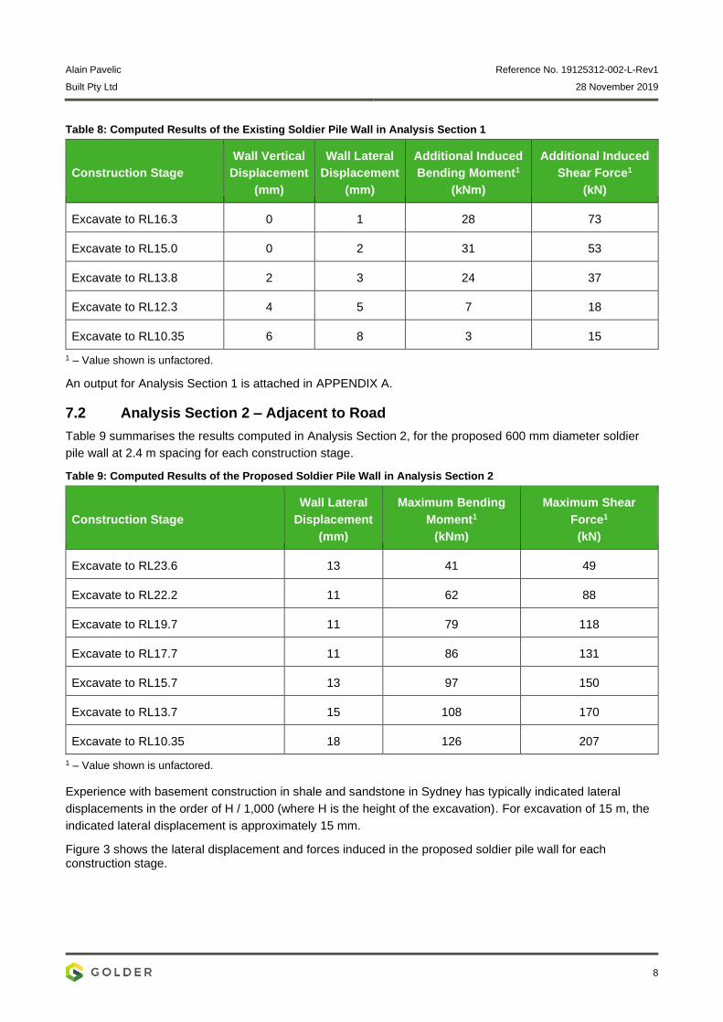
7.2 Analysis Section 2 – Adjacent to Road
Table 9 summarises the results computed in Analysis Section 2, for the proposed 600 mm diameter soldier
pile wall at 2.4 m spacing for each construction stage.
Table 9: Computed Results of the Proposed Soldier Pile Wall in Analysis Section 2
Construction Stage
Wall Lateral
Displacement
(mm)
Maximum Bending
Moment1
(kNm)
Maximum Shear
Force1
(kN)
Excavate to RL23.6 13 41 49
Excavate to RL22.2 11 62 88
Excavate to RL19.7 11 79 118
Excavate to RL17.7 11 86 131
Excavate to RL15.7 13 97 150
Excavate to RL13.7 15 108 170
Excavate to RL10.35 18 126 207
1 – Value shown is unfactored.
Experience with basement construction in shale and sandstone in Sydney has typically indicated lateral
displacements in the order of H / 1,000 (where H is the height of the excavation). For excavation of 15 m, the
indicated lateral displacement is approximately 15 mm.
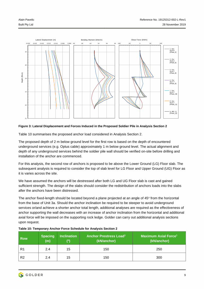
Figure 3 shows the lateral displacement and forces induced in the proposed soldier pile wall for each construction stage.
Alain Pavelic Reference No. 19125312-002-L-Rev1
Built Pty Ltd 28 November 2019
9
Figure 3: Lateral Displacement and Forces Induced in the Proposed Soldier Pile in Analysis Section 2
Table 10 summarises the proposed anchor load considered in Analysis Section 2.
The proposed depth of 2 m below ground level for the first row is based on the depth of encountered
underground services (e.g. Optus cable) approximately 1 m below ground level. The actual alignment and
depth of any underground services behind the soldier pile wall should be verified on-site before drilling and
installation of the anchor are commenced.
For this analysis, the second row of anchors is proposed to be above the Lower Ground (LG) Floor slab. The
subsequent analysis is required to consider the top of slab level for LG Floor and Upper Ground (UG) Floor as
it is varies across the site.
We have assumed the anchors will be destressed after both LG and UG Floor slab is cast and gained
sufficient strength. The design of the slabs should consider the redistribution of anchors loads into the slabs
after the anchors have been distressed.
The anchor fixed-length should be located beyond a plane projected at an angle of 45o from the horizontal
from the base of Unit 3a. Should the anchor inclination be required to be steeper to avoid underground
services or/and achieve a shorter anchor total length, additional analyses are required as the effectiveness of
anchor supporting the wall decreases with an increase of anchor inclination from the horizontal and additional
axial force will be imposed on the supporting rock ledge. Golder can carry out additional analysis sections
upon request.
Table 10: Temporary Anchor Force Schedule for Analysis Section 2
Row Spacing
(m)
Inclination
(o)
Anchor Prestress Load1
(kN/anchor)
Maximum Axial Force1
(kN/anchor)
R1 2.4 15 150 250
R2 2.4 15 150 300
21
22
23
24
25
26
-0.030 -0.025 -0.020 -0.015 -0.010 -0.005 0.000
Depth
(R
Lm
)
Lateral Displacement (m)
-50 -30 -10 10 30 50
Bending Moment (kNm/m)
-100 -50 0 50 100
Shear Force (kN/m)
1 - ExcRL23.6[Phase_4]
3 - ExcRL22.2[Phase_6]
5 - ExcRL19.7[Phase_8]
6 - ExcRL17.7[Phase_9]
7 - ExcRL15.7[Phase_10]
8 - ExcRL13.7[Phase_11]
9 - BEL 11[Phase_12]
Alain Pavelic Reference No. 19125312-002-L-Rev1
Built Pty Ltd 28 November 2019
10
1 – Value shown is unfactored.
A lateral earth pressure of 20 kPa is suggested to be adopted for the design of the shotcrete wall between the
soldier piles.
The soldier piles are recommended to be socketed 0.5 m in Unit 3a. Based on the axial load of 58 kN
computed in each of the soldier piles due to the inclination of the anchors, it is recommended that a rock ledge
be formed by having the vertical cut face at 0.2 m from the piles. Note that this bearing assessment should be
reviewed if there is additional external load applied on the piles or a change in the inclination of anchors.
An output for Analysis Section 2 is attached in APPENDIX B.
8.0 DISCUSSION AND RECOMMENDATIONS
8.1 Proposed Retention System
The proposed retention system consists of anchored soldier piles wall with shotcrete infill and vertical cuts in
the underlying competent rock (i.e. Unit 3b and 4). In addition to the recommendations as listed in Section 7.3
in our geotechnical investigation report (ref.: 19125312-001-Rev1), it is worthwhile to note the following:
We have not considered any long-term loadings. If required, the length of the soldier piles can be
extended to achieve sufficient geotechnical resistance depending on the imposed loads;
We have assumed that a temporary drainage system be designed to manage construction groundwater
inflows, which could include strip drains behind the infill shotcrete wall between the anchored soldier
piles;
The installation and testing of the anchors should be in accordance to AS5100.3. Equivalent or better
anchor type in term of axial stiffness can be adopted;
The grouted length of the ground anchor is to be assessed by an anchor contractor and these anchors
should be proof load tested to 1.25 times the Maximum Axial Force and locked off at the Anchor
Prestress Load as set out in Table 7 and Table 10;
The ground anchors in the detailed design stage (i.e. inclination, length and depth) should avoid all the
underground services;
In Analysis Section 1, we note that the existing pad footings are spaced approximately 7.5 m apart along
with the existing soldier pile wall. Upon request from Built, we can carry out further in-depth analysis such
as 3D modelling to refine the anchor and wall requirements
Excavations through shale and sandstone in Sydney may encounter adversely inclined joints that can
result in significant blocks of rock becoming dislodged from the excavation face, which may apply
additional loads to the adopted retention system as well as a potential safety risk during construction. We
consider that there is a low risk of these blocks occurring and dislodging, assuming the excavation in
rock will be carried out in 2 m depth interval and the excavated rock face is inspected by a Geotechnical
Engineer. If such inclined joints are identified on-site, it is likely that further analyses will be required;
We suggest that pattern bolting and shotcrete facing be provided for Unit 3a. We recommend that all
Laminites in Unit 3a and 3b are protected by shotcrete to prevent fretting from wetting and drying of the
rock face over time; and
We have not carried out any structural design and assessment of the retention system.
Alain Pavelic Reference No. 19125312-002-L-Rev1
Built Pty Ltd 28 November 2019
11
The information contained in this report is sensitive to the suitability of the assumptions made and discussed
throughout. If any of these assumptions are found to be inappropriate, it may be necessary to carry out further
analyses and to revise this report.
8.2 The Adjacent Building North-West of the Site
An analysis section, Analysis Section 1, has carried out considering the foundation load (provided by RBG)
from the adjacent building behind the proposed soldier pile wall. This report has included an estimated
displacement of the footings and forces induced in the soldier pile wall due to excavation. We have not
assessed the impact of the construction works and excavation on this building.
Due to the relatively high foundation load from this building, the proposed soldier pile is to be constructed
through Unit 3b (medium to high strength Laminite) and terminated on the top of Unit 4 (high to very high
strength Sandstone).
Based on the drawings provided, the excavation is expected to expose the buried ground anchors of the
adjacent building. Prior commencement of excavation, an agreed method of excavating and removal of the
existing anchor should be developed with the involvement of the relevant stakeholders and structural
engineers.
The proposed soldier piles are designed at 1.5 m spacing, identical to the spacing of the existing soldier pile
for this adjacent building. The proposed soldier piles should be installed between the span of the existing
soldier piles, allowing the proposed ground anchors can be installed without obstruction by these existing
soldier piles.
The proposed ground anchors are below the groundwater table and within the zone providing geotechnical
resistance to the foundation of the existing building. The construction and installation of ground anchor should
consider any disturbance may reduce the available geotechnical resistance to the existing foundation.
Alain Pavelic Reference No. 19125312-002-L-Rev1
Built Pty Ltd 28 November 2019
12
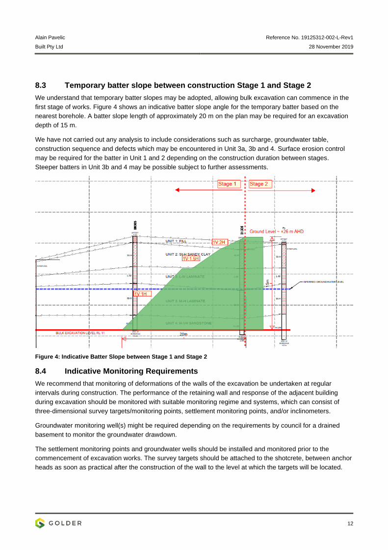
8.3 Temporary batter slope between construction Stage 1 and Stage 2
We understand that temporary batter slopes may be adopted, allowing bulk excavation can commence in the
first stage of works. Figure 4 shows an indicative batter slope angle for the temporary batter based on the
nearest borehole. A batter slope length of approximately 20 m on the plan may be required for an excavation
depth of 15 m.
We have not carried out any analysis to include considerations such as surcharge, groundwater table,
construction sequence and defects which may be encountered in Unit 3a, 3b and 4. Surface erosion control
may be required for the batter in Unit 1 and 2 depending on the construction duration between stages.
Steeper batters in Unit 3b and 4 may be possible subject to further assessments.
Figure 4: Indicative Batter Slope between Stage 1 and Stage 2
8.4 Indicative Monitoring Requirements
We recommend that monitoring of deformations of the walls of the excavation be undertaken at regular
intervals during construction. The performance of the retaining wall and response of the adjacent building
during excavation should be monitored with suitable monitoring regime and systems, which can consist of
three-dimensional survey targets/monitoring points, settlement monitoring points, and/or inclinometers.
Groundwater monitoring well(s) might be required depending on the requirements by council for a drained
basement to monitor the groundwater drawdown.
The settlement monitoring points and groundwater wells should be installed and monitored prior to the
commencement of excavation works. The survey targets should be attached to the shotcrete, between anchor
heads as soon as practical after the construction of the wall to the level at which the targets will be located.
Alain Pavelic Reference No. 19125312-002-L-Rev1
Built Pty Ltd 28 November 2019
13
Due to the proximity of the excavation to the building adjacent to the north-west of the site, the building is
expected to be susceptible to damage from vibrations when rock excavations are made in the immediate
vicinity. We anticipate vibration monitoring would be required to verify allowable limits is achieved on site.
If requested, we can develop a Geotechnical Monitoring Programme presenting:
Monitoring and instrumentation requirements;
Recommended hold points and trigger levels of all monitoring systems; and
Details of action plan and contingency for the principal building contractor in the event trigger levels are
exceeded.
9.0 IMPORTANT INFORMATION
Your attention is drawn to the document “Important Information”, which is attached to APPENDIX C of this
report. The statements presented in this document are intended to advise you of what your realistic
expectations of this report should be and to present you with recommendations on how to minimise the risks
associated with the services provided for this project. The document is not intended to reduce the level of
responsibility accepted by Golder Associates, but rather to ensure that all parties who may rely on this report
are aware of the responsibilities each assumes in so doing.
Golder Associates Pty Ltd
Eric Woon Les McQueen
Senior Geotechnical Engineer Principal Engineer
EW/LM:JM/ew
https://golderassociates.sharepoint.com/sites/112254/project files/6 deliverables/002-r-additional geo assessment/19125312-002-l-rev1 additional geo assessment.docx

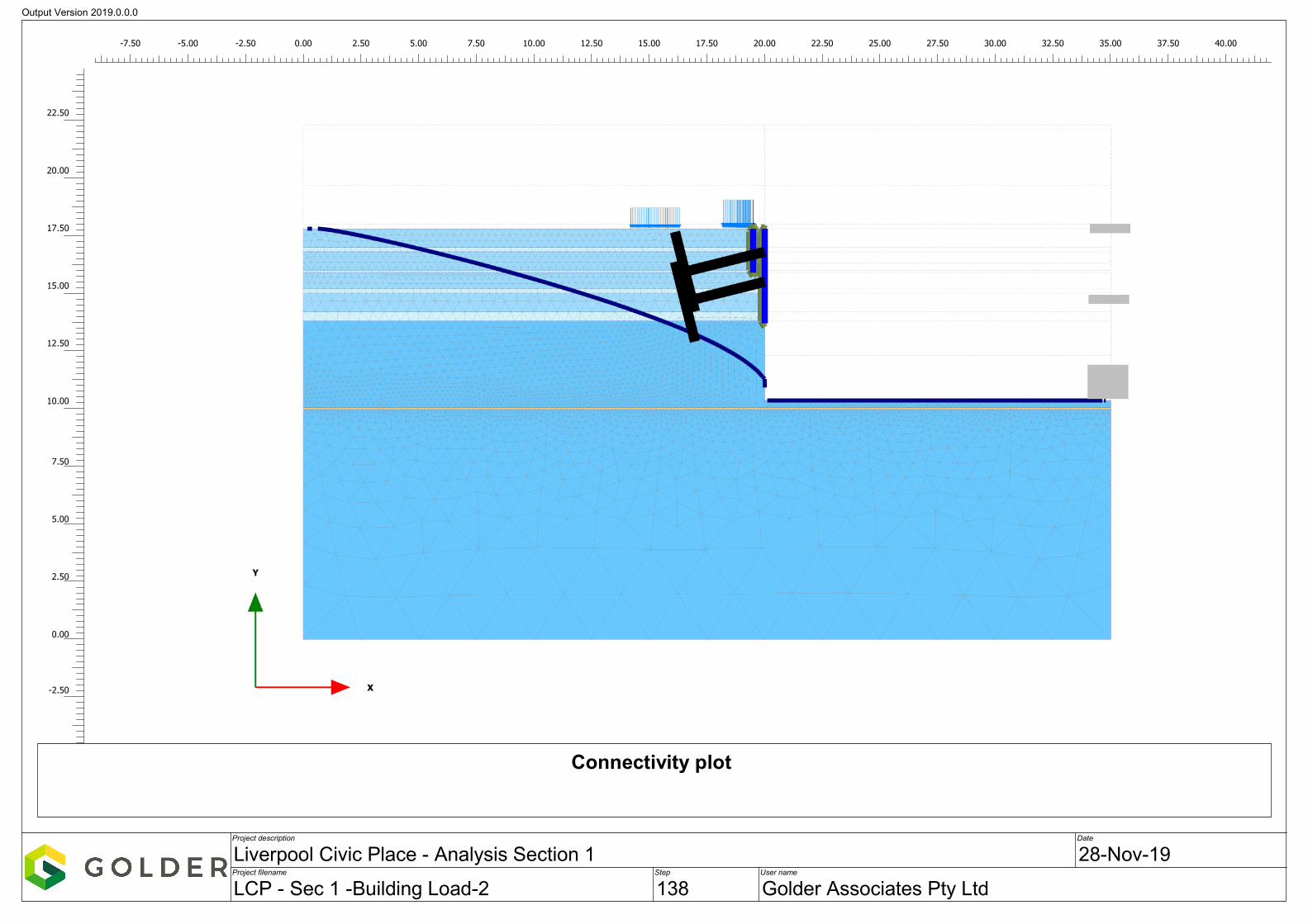
APPENDIX A
Analysis Output for Section 1
Output Version 2019.0.0.0
Project description
Project filename Step
Date
User name
Liverpool Civic Place - Analysis Section 1 28-Nov-19
LCP - Sec 1 -Building Load-2 138 Golder Associates Pty Ltd
Connectivity plot
-7.50 -5.00 -2.50 0.00 2.50 5.00 7.50 10.00 12.50 15.00 17.50 20.00 22.50 25.00 27.50 30.00 32.50 35.00 37.50 40.00
-2.50
0.00
2.50
5.00
7.50
10.00
12.50
15.00
17.50
20.00
22.50
ErWoon
Typewriter
470 kN/m/m
ErWoon
Arrow
ErWoon
Typewriter
Unit 3b
ErWoon
Arrow
ErWoon
Typewriter
Unit 4
ErWoon
Typewriter
RL +17.8 m AHD
ErWoon
Typewriter
RL +13.8 m AHD
ErWoon
Typewriter
BEL +10.35 m AHD
ErWoon
Arrow
ErWoon
Typewriter
335 kN/m
ErWoon
Arrow
ErWoon
Arrow
ErWoon
Arrow
ErWoon
Typewriter
7.5 m
ErWoon
Typewriter
Row 1 Anchor at RL +16.8 m AHD with waler
ErWoon
Typewriter
Row 2 Anchor at RL +15.5 m AHD with waler
ErWoon
Line
ErWoon
Line
ErWoon
Arrow
ErWoon
Typewriter
Existing Soldier Pile Wall 0.6 m diameter at 1.5 m spacing
ErWoon
Typewriter
GL +22.3 m AHD
ErWoon
Typewriter
GWT +18.0 m AHD
ErWoon
Arrow
ErWoon
Typewriter
GL +22.3 m AHD
ErWoon
Arrow
ErWoon
Typewriter
12 m
ErWoon
Typewriter
Analysis Section 1
ErWoon
Typewriter
650 kN/m/m
ErWoon
Arrow
ErWoon
Typewriter
1.0 m
ErWoon
Arrow
ErWoon
Typewriter
1.3 m
ErWoon
Typewriter
Spot Bolt as required in Unit 4
ErWoon
Typewriter
depends on rock face inspection
ErWoon
Typewriter
Proposed Soldier Pile Wall 0.6 m diameter at 1.5 m spacing
ErWoon
Typewriter
Recommended 0.5 m into Unit 4
ErWoon
Typewriter
Drainage strips behind the wall
ErWoon
Arrow
ErWoon
Rectangle
ErWoon
Rectangle
ErWoon
Typewriter
B3 +11.95 m AHD
ErWoon
Typewriter
B2 +14.95 m AHD
ErWoon
Typewriter
B1 +17.95 m AHD
ErWoon
Rectangle
ErWoon
Arrow
ErWoon
Typewriter
1.7 m
ErWoon
Arrow
ErWoon
Typewriter
Rock bolt may be required 0.5 m below pile toe

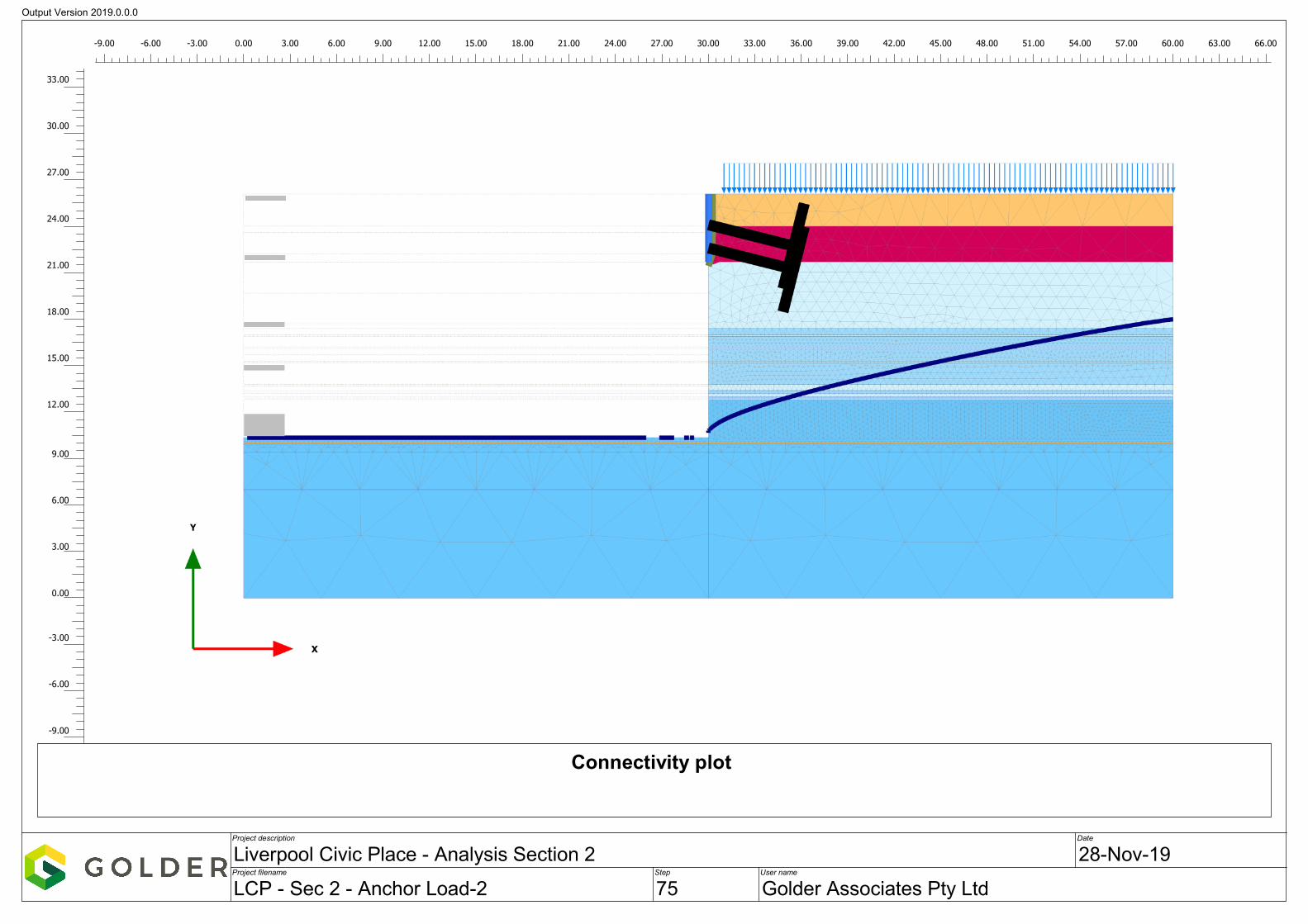
APPENDIX B
Analysis Output for Section 2
Output Version 2019.0.0.0
Project description
Project filename Step
Date
User name
Liverpool Civic Place - Analysis Section 2 28-Nov-19
LCP - Sec 2 - Anchor Load-2 75 Golder Associates Pty Ltd
Connectivity plot
-9.00 -6.00 -3.00 0.00 3.00 6.00 9.00 12.00 15.00 18.00 21.00 24.00 27.00 30.00 33.00 36.00 39.00 42.00 45.00 48.00 51.00 54.00 57.00 60.00 63.00 66.00
-9.00
-6.00
-3.00
0.00
3.00
6.00
9.00
12.00
15.00
18.00
21.00
24.00
27.00
30.00
33.00
ErWoon
Arrow
ErWoon
Typewriter
Unit 3b
ErWoon
Arrow
ErWoon
Typewriter
Unit 4
ErWoon
Typewriter
GL +26.1 m AHD
ErWoon
Typewriter
GWT +18.0 m AHD
ErWoon
Arrow
ErWoon
Typewriter
Unit 3a
ErWoon
Typewriter
Unit 2
ErWoon
Typewriter
Unit 1
ErWoon
Arrow
ErWoon
Arrow
ErWoon
Typewriter
20 kN/m/m
ErWoon
Arrow
ErWoon
Typewriter
1 m
ErWoon
Typewriter
BEL +10.35 m AHD
ErWoon
Typewriter
Row 1 Anchor at RL +24.1 m AHD
ErWoon
Typewriter
Row 2 Anchor at RL +22.6 m AHD
ErWoon
Line
ErWoon
Line
ErWoon
Arrow
ErWoon
Typewriter
GL +26.1 m AHD
ErWoon
Typewriter
16 m
ErWoon
Typewriter
Proposed Soldier Pile Wall 0.6 m diameter at 2.4 m spacing
ErWoon
Arrow
ErWoon
Arrow
ErWoon
Arrow
ErWoon
Arrow
ErWoon
Typewriter
2.0 m
ErWoon
Typewriter
Recommended 0.5 m socket into Unit 3a
ErWoon
Typewriter
Pattern Rock Bolt with shotcrete facing for Unit 3a
ErWoon
Typewriter
Spot Bolt as required in Unit 3b and 4
ErWoon
Typewriter
depends on rock face inspection
ErWoon
Arrow
ErWoon
Typewriter
1.5 m
ErWoon
Typewriter
Analysis Section 2
ErWoon
Typewriter
Drainage strips behind the wall
ErWoon
Typewriter
Drainage strips behind the wall or drainage holes
ErWoon
Line
ErWoon
Typewriter
B1 +17.95 m AHD
ErWoon
Rectangle
ErWoon
Typewriter
B3 +11.95 m AHD
ErWoon
Rectangle
ErWoon
Typewriter
B2 +14.95 m AHD
ErWoon
Rectangle
ErWoon
Rectangle
ErWoon
Typewriter
LG* +22.3 m AHD
ErWoon
Typewriter
UG* +26.0 m AHD
ErWoon
Rectangle
ErWoon
Typewriter
* Top of levels varies across the site

APPENDIX C
Important Information

GOLDER ASSOCIATES PTY LTD
IMPORTANT INFORMATION RELATING TO THIS REPORT
Error! Unknown document property name. Page 1 of 1 GAP Form No. LEG04 RL2
5/2018
The document (“Report”) to which this page is attached and which this page forms a part of, has been issued
by Golder Associates Pty Ltd (“Golder”) subject to the important limitations and other qualifications set out below.
This Report constitutes or is part of services (“Services”) provided by Golder to its client (“Client”) under and subject
to a contract between Golder and its Client (“Contract”). The contents of this page are not intended to and do not
alter Golder’s obligations (including any limits on those obligations) to its Client under the Contract.
This Report is provided for use solely by Golder’s Client and persons acting on the Client’s behalf, such as its
professional advisers. Golder is responsible only to its Client for this Report. Golder has no responsibility to any other
person who relies or makes decisions based upon this Report or who makes any other use of this Report. Golder
accepts no responsibility for any loss or damage suffered by any person other than its Client as a result of any
reliance upon any part of this Report, decisions made based upon this Report or any other use of it.
This Report has been prepared in the context of the circumstances and purposes referred to in, or derived from,
the Contract and Golder accepts no responsibility for use of the Report, in whole or in part, in any other context
or circumstance or for any other purpose.
The scope of Golder’s Services and the period of time they relate to are determined by the Contract and are subject to restrictions and limitations set out in the Contract. If a service or other work is not expressly referred to in this Report, do not assume that it has been provided or performed. If a matter is not addressed in this Report, do not assume that any determination has been made by Golder in regards to it.
At any location relevant to the Services conditions may exist which were not detected by Golder, in particular due to
the specific scope of the investigation Golder has been engaged to undertake. Conditions can only be verified at the
exact location of any tests undertaken. Variations in conditions may occur between tested locations and there may
be conditions which have not been revealed by the investigation and which have not therefore been taken into account
in this Report.
Golder accepts no responsibility for and makes no representation as to the accuracy or completeness of the
information provided to it by or on behalf of the Client or sourced from any third party. Golder has assumed that such
information is correct unless otherwise stated and no responsibility is accepted by Golder for incomplete or
inaccurate data supplied by its Client or any other person for whom Golder is not responsible. Golder has not taken
account of matters that may have existed when the Report was prepared but which were only later disclosed to
Golder.
Having regard to the matters referred to in the previous paragraphs on this page in particular, carrying out the
Services has allowed Golder to form no more than an opinion as to the actual conditions at any relevant location.
That opinion is necessarily constrained by the extent of the information collected by Golder or otherwise made
available to Golder. Further, the passage of time may affect the accuracy, applicability or usefulness of the opinions,
assessments or other information in this Report. This Report is based upon the information and other circumstances
that existed and were known to Golder when the Services were performed and this Report was prepared.
Golder has not considered the effect of any possible future developments including physical changes to any
relevant location or changes to any laws or regulations relevant to such location.
Where permitted by the Contract, Golder may have retained subconsultants affiliated with Golder to provide some or all of the Services. However, it is Golder which remains solely responsible for the Services and there is no legal recourse against any of Golder’s affiliated companies or the employees, officers or directors of any of them.
By date, or revision, the Report supersedes any prior report or other document issued by Golder dealing with any
matter that is addressed in the Report.
Any uncertainty as to the extent to which this Report can be used or relied upon in any respect should be
referred to Golder for clarification


![XQuery 1.0 and XPath 2.0 Data Model - CorporationTransformations] 2.0 and [XQuery 1.0: A Query Language for XML] 1.0. The XQuery 1.0 and XPath 2.0 Data Model (henceworth "data model")](https://static.fdocuments.in/doc/165x107/603ed13675d53145ee662725/xquery-10-and-xpath-20-data-model-corporation-transformations-20-and-xquery.jpg)