10” HYBRID SAW - The Home Depot · 2 YOU able inspected and of the business. Steel of of...
44
STEEL CITY TOOL WORKS VER. 08.2014 Manual Part No. SC76038N C US ® 10” HYBRID SAW User Manual Read and understand this manual before using machine. Model Number 45925G 45925C
Transcript of 10” HYBRID SAW - The Home Depot · 2 YOU able inspected and of the business. Steel of of...

STEEL CITY TOOL WORKSVER. 08.2014 Manual Part No. SC76038N
C US®
10” HYBRID SAW
User ManualRead and understand this manual before using machine.
Model Number45925G45925C

2
THANK YOU for purchasing your new Steel City Table
Saw. This table saw has been designed, tested, and inspected
with you, the customer, in mind. When properly used and
maintained, your table saw will provide you with years of
trouble free service, which is why it is backed by one of the
longest machinery warranties in the business.
This table saw is just one of many products in the Steel
City’s family of woodworking machinery and is proof of
our commitment to total customer satisfaction.
At Steel City we continue to strive for excellence each and
every day and value the opinion of you, our customer. For
comments about your table saw or Steel City Tool Works,
please visit our web site at www.steelcitytoolworks.com .

3
TABLE OF CONTENTS
INTRODUCTION
This user manual is intended for use by anyone working with this machine. It should be kept availablefor immediate reference so that all operations can be performed with maximum efficiency and safety.Do not attempt to perform maintenance or operate this machine until you have read and understand theinformation contained in this manual.
The drawings, illustrations, photographs, and specifications in this user manual represent your machineat time of print. However, changes may be made to your machine or this manual at any time with noobligation to Steel City Tool Works.
INTRODUCTION
SECTION 1 Warranty .................................................................................................................................................4
SECTION 2 Product Specifications ............................................................................................................................7
SECTION 3 Accessories and Attachments ................................................................................................................7
SECTION 4 Definition of Terms..................................................................................................................................8
SECTION 5 Feature Identification ..............................................................................................................................9
SECTION 6 General Safety......................................................................................................................................10
SECTION 7 Product Safety ......................................................................................................................................12
SECTION 8 Electrical Requirements........................................................................................................................13
SECTION 9 Grounding Instructions..........................................................................................................................14
SECTION 10 Unpacking & Inventory..........................................................................................................................15
SECTION 11 Assembly ..............................................................................................................................................17
SECTION 12 Adjustments............................................................................................................................................24
SECTION 13 Maintenance .........................................................................................................................................28
Maintenance .........................................................................................................................................33SECTION 14
SECTION 15
SECTION 16
Troubleshooting Guide..........................................................................................................................34
Parts List...............................................................................................................................................36
Operation.....

2 YEAR LIMITED WARRANTY Steel City Tool Works, LLC (SCTW) warrants this SCTW machinery to be free of defects in workmanship and materials for a period of 2 years from the date of the original retail purchase by the original owner for domestic use. Granite components are warranted for 2 years based on normal use and is void if non SCTW accessories are used that cause the break or chip. Customer must advise SCTW within 30 days for any damage or defect found upon receipt of the product to qualify for the warranty on granite.
The warranty does not cover any product used for professional or commercial production purpose nor for industrial or educationalapplications. Such cases are covered by our 1 year Limited Warranty with the Conditions and Exceptions listed below.
Conditions and exception:
Warranty applies to the original buyer only and may not be transferred. Original proof of purchase is required.
Warranty does not include failures, breakage or defects deemed after inspection by an Authorized Service Center, (ASC) or agent of, have been directly or indirectly caused by or resulting from improper use, lack of or improper maintenance, misuse or abuse, negligence, accidents, damage in handling or transport, or normal wear and tear of any part or component.
Additionally, warranty is void if repairs or alterations are made to the machine by an unauthorized service center without the direct consent of SCTW
Consumables such as blades, knives, bits and sandpaper are not covered. Wear items such as drive belt, bearings, switch, are covered for 1 year.
To file a claim of warranty or to find a service center, call toll free 877-724-8665 or email [email protected] and you must be able to present the original or photo copy of the sales receipt including the serial number from the machine and/or carton.
SCTW will inspect, repair or replace, at its expense and its option, any part that has proven to be defective in workmanship ormaterial, provided that the customer returns the product prepaid to a designated ASC and provides SCTW with a reasonable opportunity to verify the alleged defect by inspection. SCTW will return the product or replacement at our expense unless it isdetermined by us that there is no defect or that the defect resulted from causes not within the scope of our warranty in which case we will, at your direction, dispose of or return the product. In the event you choose to have the product returned, you will be responsible for the handling and shipping costs of the return.
SCTW furnishes the above warranties in lieu of all other warranties, express or implied. SCTW shall not be liable for any special,indirect, incidental, punitive or consequential damages, including without limitation loss of profits arising from or related to the warranty, the breach of any agreement or warranty, or the operation or use of its machinery, including without limitation damagesarising from damage to fixtures, tools, equipment, parts or materials, direct or indirect loss caused by and other part, loss of revenue or profits, financing or interest charges, and claims by and third person, whether or not notice of such possible damages has been given to SCTW. Damages or any kind for any delay by or failure of SCTW to perform its obligations under this agreement or claimsmade a subject of a legal proceeding against SCTW more than one (1) year after such cause of action first arose.
The validity, construction and performance of this Warranty and any sale of machinery by SCTW shall be governed by the law of theCommonwealth of Pennsylvania, without regard to conflicts of law’s provisions of any jurisdiction. Any action related in any way to any alleged or actual offer, acceptance or sale by SCTW or any claim related to the performance of and agreement including without limitation this Warranty, shall take place in the federal or state courts in Allegheny County, Pennsylvania.
Warranty registration card must be submitted to SCTW for purpose of proof within 90 days of purchase with a copy of the sales receipt. Failure to do so will, revert the 2 year warranty to 1 year as in the terms stated above. This registration is also needed to facilitate contact in case of a safety recall.
This warranty gives you specific legal rights and you may have other rights which vary in certain States or Provinces.
Note to userThis instruction manual is meant to serve as a guide only. Specification and references are subject to change without prior notice. Check the website www.steelcitytoolworks.com for updated manuals with reference to the VER# located on the front page.
LIMITED WARRANTY – ACCU-SHOP line of bench top tools Steel City Tool Works, LLC (SCTW) warrants this SCTW ACCU-SHOP machinery to be free of defects in workmanship and materials for a period of 2 years from the date of the original retail purchase by the original owner for domestic use. Consumables such as blades, knives, bits and sandpaper are not covered. Wear items such as drive belt, bearings, switch, are covered for 1 year.
The warranty does not cover any product used for professional or commercial production purpose nor for industrial or educationalapplications. Such cases are covered by our 30 days Limited Warranty with the Conditions and Exceptions listed previously.
WARRANTY
4

5
CU
TH
ER
E
WARRANTY CARDName ________________________________________________
Street _______________________________________________
Apt. No. ______________________________________________
City_________________________ State ______ Zip __________
Phone Number_________________________________________
E-Mail________________________________________________
Product Description:_____________________________________
Model No.:_________________ Serial No.: _________________
The following information is given on a voluntary basisand is strictly confidential.
1. Where did you purchase your STEEL CITY machine?
Store: ____________________________________________
City:______________________________________________ Online:______________________________________________
2. How did you first learn of Steel City Tool Works?
___ Advertisement ___ Mail Order Catalog
___ Web Site ___ Friend
___ Local Store Other_______________________
3. Which of the following magazines do you subscribe to?
___
___
American Woodworker ___ Cabinetmaker
Canadian Woodworking ___ Family Handyman
___ Fine Homebuilding ___ Fine Woodworking
___ Journal of Light Construction ___ Old House Journal
___ Popular Mechanics ___ Popular Science
___ Popular Woodworking ___ Today’s Homeowner
tfarcdooW___DOOW___
___ WOODEN Boat ___ Woodshop News
___ Woodsmith ___ Woodwork
___ Woodworker ___ Woodworker’s Journal
___ Workbench Other_________________
4. Which of the following woodworking / remodeling shows doyou watch?
___ Backyard America ___ The American Woodworker
___ Home Time ___ The New Yankee Workshop
___ This Old House ___ Woodwright’s Shop
Other__________________________________________
5. What is your annual household income?
___ $20,000 to $29,999 ___ $30,000 to $39,999
___ $40,000 to $49,999 ___ $50,000 to $59,999
___ $60,000 to $69,999 ___ 70,000 to $79,999
___ $80,000 to $89,999 ___ $90,000 +
6. What is your age group?
___ 20 to 29 years ___ 30 to 39 years
___ 40 to 49 years ___ 50 to 59 years
___ 60 to 69 years ___ 70 + years
7. How long have you been a woodworker?
___ 0 to 2 years ___ 2 to 8 years
___ 8 to 20 years ___ over 20 years
8. How would you rank your woodworking skills?
___ Simple ___ Intermediate
___ Advance ___ Master Craftsman
9. How many Steel City machines do you own? _____________
10. What stationary woodworking tools do you own?Check all that apply.
___ Air Compressor ___ Band Saw
___ Drill Press ___ Drum Sander
___ Dust Collection ___ Horizontal Boring Machine
___ Jointer ___ Lathe
___ Mortiser ___ Panel Saw
___ Planer ___ Power Feeder
___ Radial Arm Saw ___ Shaper
___ Spindle Sander ___ Table Saw
___ Vacuum Veneer Press ___ Wide Belt Sander
Other____________________________________________
11. Which benchtop tools do you own? Check all that apply.
___ Belt Sander ___ Belt / Disc Sander
___ Drill Press ___ Band Saw
___ Grinder ___ Mini Jointer
___ Mini Lathe ___ Scroll Saw
___ Spindle / Belt Sander Other______________________
12. Which portable / hand held power tools do you own?Check all that apply.
___ Belt Sander ___ Biscuit Jointer
___ Dust Collector ___ Circular Saw
___ Detail Sander ___ Drill / Driver
___ Miter Saw ___ Orbital Sander
___ Palm Sander ___ Portable Thickness Planer
___ Saber Saw ___ Reciprocating Saw
___ Router Other_______________________
13. What machines / accessories would you like to see added to theSTEEL CITY line?
____________________________________________________
____________________________________________________
14. What new accessories would you like to see added?
____________________________________________________
____________________________________________________
15. Do you think your purchase represents good value?
___Yes ___ No
16. Would you recommend STEEL CITY products to a friend?
___ Yes ___ No
17. Comments:
____________________________________________________
____________________________________________________
____________________________________________________
____________________________________________________
____________________________________________________
NOTE: The Proof of Purchase must be submitted along with this card in order to have the Warranty to take into effect. Fail to submit the Proof of Purchase may invalidate your Product Warranty.

FOLD ON DOTTED LINE
FOLD ON DOTTED LINE
PLACE
STAMP
HER
SteelCityToolWorks
#4 Northpoint Court
Bolingbrook, IL 60440
E
6

Motor typeHPAmpsVoltsHertzRPMBlade TiltBlade DriveBlade DiameterBlade ArborNumber of TeethBlade SpeedMax Depth of cut at 90°Max Depth of cut at 45°Table in front of blade at max depth of cutMax Dado widthMax Dado blade diameterLeft Extension table wingRight Extention table wing
Induction1.513/6.5120/240603450LeftPoly-V Belt10-in5/8-in4034503-3/8-in2-1/2-in12-1/2-in
13/16-in8-in13.7-in Granite14.9-in Granite
Induction1.513/6.5120/240603450LeftPoly-V Belt10-in5/8-in4034503-3/8-in2-1/2-in12-1/2-in
13/16-in8-in13.7-in Cast Iron14.9-in Cast Iron
LengthWidthHeightNet Werght
68”38”35-1/2”348 lbs
68”38”35-1/2”313 lbs
LengthWidthHeightGross Werght
31.5-in30.1-in21.7-in363 lbs
31.5-in30.1-in21.7-in328 lbs
45925G 45925C
Product Dimensions
Shipping Dimensions
PRODUCT SPECIFICATIONS
ACCESSORIES AND ATTACHMENTSDado Insert: 35830Zero Clearance Insert: 35831
There are more accessories available for your Steel City Product. For more informations on any accessories associated with this and other machines, please contact your nearest Steel City distributor, or visit our website at: www.steelcitytoolworks.com
7

8
DEFINITION OF TERMS
Anti-Kickback Fingers – A safety device attached tothe blade guard and splitter assembly designed tominimize the chance of a workpiece being thrown backduring a cutting operation.
Arbor – The shaft on which the blade or accessorycutting-tool is mounted.
Bevel Cut – The operation of making any cut with theblade set on a degree other than 90 degrees.
Compound Cut – The operation of making both abevel and a miter cut at one time.
Crosscut – The operation of making a cut across thegrain or width of a workpiece.
Dado – A non-through cut that produces a squarenotch. A dado is typically from 1/8-in. to 13/16-in. wide.A dado requires a special set of blades, not includedwith this table saw.
Featherboard – An accessory device that can be madeor purchased to help guide or hold down a workpieceduring cutting operations.
Freehand – A very dangerous operation of making acut without using the fence or miter gauge in a cuttingoperation. FREEHAND CUTS MUST NEVER BEPERFORMED ON A TABLE SAW.
Gum, Pitch or Resin – A sticky, sap based residue thatcomes from wood products.
Heeling – The misalignment of the blade to the miterslots; when the blade is not parallel to the miter slots.
Kerf – The material removed by the blade in the work-piece during any cutting operation.
Kickback – When the workpiece is thrown back towardthe operator at a high rate of speed during a cuttingoperation.
Miter Cut – The operation of making a cut using themiter gauge at any angle other than zero degrees.
Push Stick – An accessory device that can be made orpurchased to help push the workpiece through theblade. A push stick is used to keep the operator’shands away from the blade when ripping a narrowworkpiece.
Rabbet – A square notch in the edge of the workpiece.
Rip Cut – The operation of making a cut with the grainof the workpiece.
Saw Blade Path – The area that is directly in line withthe blade, including area over, under, behind and infront of it.
Set of the Saw Blade – The distance that the tips ofthe saw blade are angled outwards from the thicknessof the blade. The set of the saw blade teeth allows forthe blade body to pass safely through all cuts.
Table/Work Area – The total surface of the top of thetable saw on which the workpiece rests while set-up orcutting operations are being performed.
9
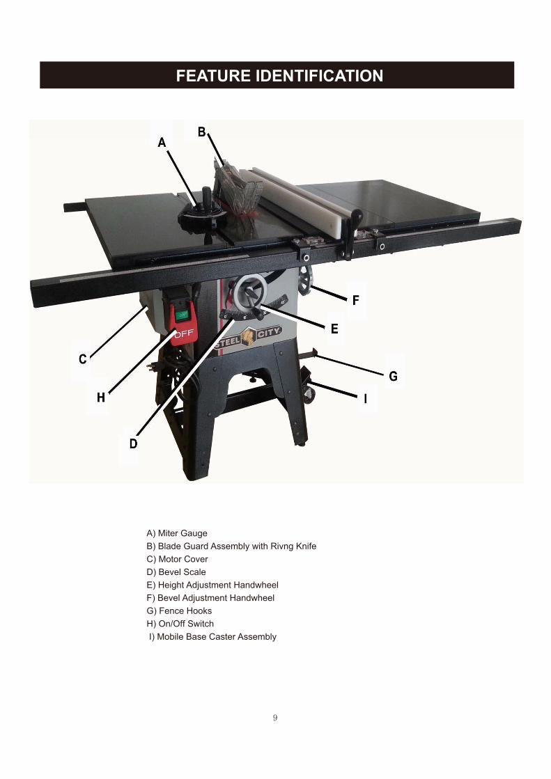
FEATURE IDENTIFICATION
A) Miter GaugeB) Blade Guard Assembly with Rivng KnifeC) Motor CoverD) Bevel ScaleE) Height Adjustment HandwheelF) Bevel Adjustment HandwheelG) Fence HooksH) On/Off Switch I) Mobile Base Caster Assembly
10
TO AVOID serious injury and damage to the machine,read and follow all Safety and Operating Instructionsbefore assembling and operating this machine.
This manual is not totally comprehensive. It does notand can not convey every possible safety and opera-tional problem which may arise while using thismachine. The manual will cover many of the basic andspecific safety procedures needed in an industrial envi-ronment.
All federal and state laws and any regulations havingjurisdiction covering the safety requirements for use ofthis machine take precedence over the statements inthis manual. Users of this machine must adhere to allsuch regulations.
Below is a list of symbols that are used to attract yourattention to possible dangerous conditions.
This is the safety alert symbol. It is used to alert you topotential personal injury hazards. Obey all safety mes-sages that follow this symbol to avoid possible injury ordeath.
Indicates an imminently hazardous situation which, ifnot avoided, WILL result in death or serious injury.
Indicates a potentially hazardous situation which, if notavoided, COULD result in death or serious injury.
Indicates a potentially hazardous situation, if not avoid-ed, MAY result in minor or moderate injury. It may alsobe used to alert against unsafe practices.
CAUTION used without the safety alert symbol indi-cates a potentially hazardous situation which, if notavoided, may result in property damage.
This symbol is used to alert the user to useful informa-tion about proper operation of the machine.
GENERAL SAFETY
DANGER
NOTICE
CAUTION
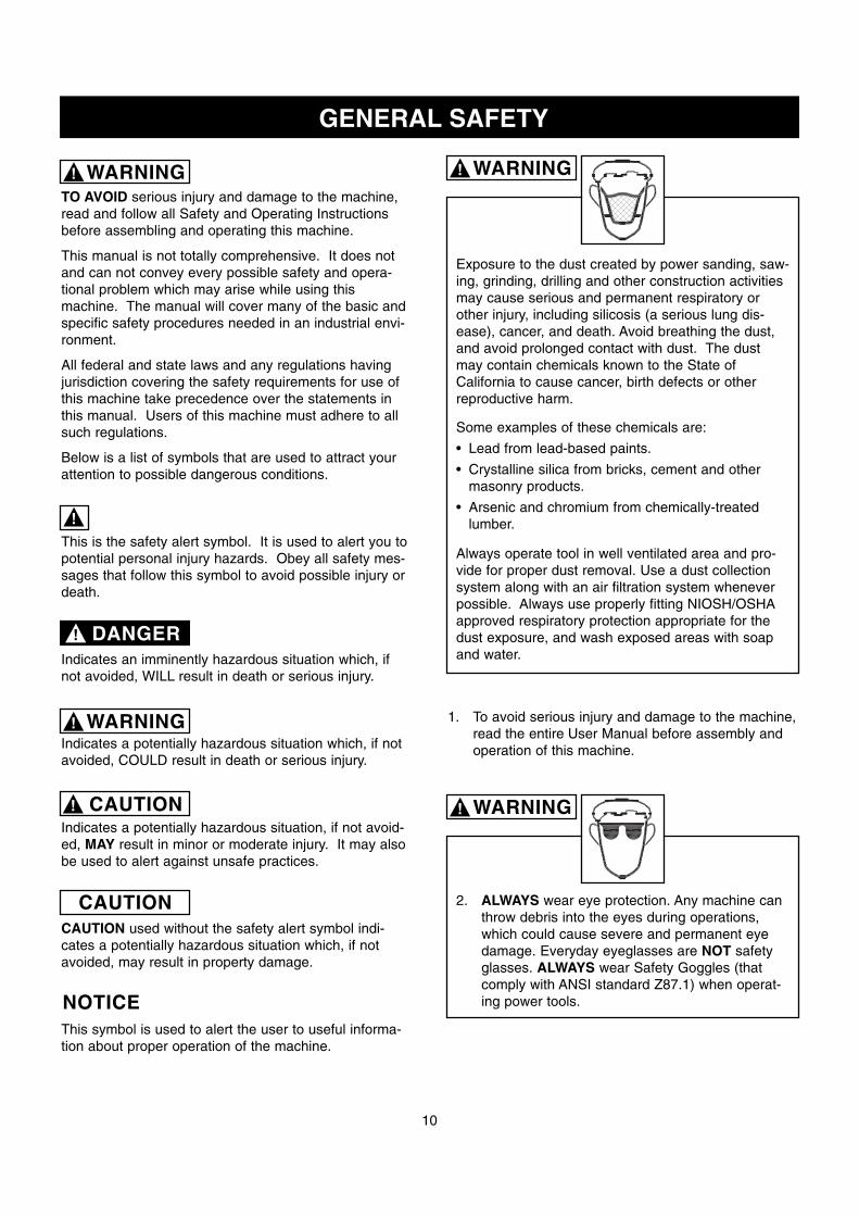
Exposure to the dust created by power sanding, saw-ing, grinding, drilling and other construction activitiesmay cause serious and permanent respiratory orother injury, including silicosis (a serious lung dis-ease), cancer, and death. Avoid breathing the dust,and avoid prolonged contact with dust. The dustmay contain chemicals known to the State ofCalifornia to cause cancer, birth defects or otherreproductive harm.
2. ALWAYS wear eye protection. Any machine canthrow debris into the eyes during operations,which could cause severe and permanent eyedamage. Everyday eyeglasses are NOT safetyglasses. ALWAYS wear Safety Goggles (thatcomply with ANSI standard Z87.1) when operat-ing power tools.
WARNING
WARNING
CAUTION
!
!
!
!
! WARNING!
Some examples of these chemicals are:
• Lead from lead-based paints.
• Crystalline silica from bricks, cement and othermasonry products.
• Arsenic and chromium from chemically-treatedlumber.
Always operate tool in well ventilated area and pro-vide for proper dust removal. Use a dust collectionsystem along with an air filtration system wheneverpossible. Always use properly fitting NIOSH/OSHAapproved respiratory protection appropriate for thedust exposure, and wash exposed areas with soapand water.
WARNING!
1. To avoid serious injury and damage to the machine,read the entire User Manual before assembly andoperation of this machine.
11
4. ALWAYS wear a NIOSH/OSHA approved dustmask to prevent inhaling dangerous dust or air-borne particles.
8. AVOID a dangerous working environment. DONOT use electrical tools in a damp environmentor expose them to rain or moisture.
9. CHILDPROOF THE WORKSHOP AREA byremoving switch keys, unplugging tools from theelectrical receptacles, and using padlocks.
3. ALWAYS wear hearing protection. Plain cotton isnot an acceptable protective device. Hearingequipment should comply with ANSI S3.19Standards.
WARNING!
WARNING!
WARNING!
WARNING!
11. DO NOT FORCE the machine to perform an opera-tion for which it was not designed. It will do a saferand higher quality job by only performing operationsfor which the machine was intended.
12. DO NOT stand on a machine. Serious injury couldresult if it tips over or you accidentally contact anymoving part.
13. DO NOT store anything above or near the machine.
14. DO NOT operate any machine or tool if under theinfluence of drugs, alcohol, or medication.
15. EACH AND EVERY time, check for damaged partsprior to using any machine. Carefully check allguards to see that they operate properly, are notdamaged, and perform their intended functions.Check for alignment, binding or breakage of allmoving parts. Any guard or other part that is dam-aged should be immediately repaired or replaced.
16. Ground all machines. If any machine is suppliedwith a 3-prong plug, it must be plugged into a 3-contact electrical receptacle. The third prong isused to ground the tool and provide protectionagainst accidental electric shock. DO NOT removethe third prong.
17. Keep visitors and children away from any machine.DO NOT permit people to be in the immediate workarea, especially when the machine is operating.
18. KEEP protective guards in place and in workingorder.
19. MAINTAIN your balance. DO NOT extend yourselfover the tool. Wear oil resistant rubber soled shoes.Keep floor clear of debris, grease, and wax.
20. MAINTAIN all machines with care. ALWAYS KEEPmachine clean and in good working order. KEEP allblades and tool bits sharp.
21. NEVER leave a machine running, unattended. Turnthe power switch to the OFF position. DO NOTleave the machine until it has come to a completestop.
22. REMOVE ALL MAINTENANCE TOOLS from theimmediate area prior to turning the machine ON.
23. SECURE all work. When it is possible, use clampsor jigs to secure the workpiece. This is safer thanattempting to hold the workpiece with your hands.
24. STAY ALERT, watch what you are doing, and usecommon sense when operating any machine. DONOT operate any machine tool while tired or underthe influence of drugs, alcohol, or medication. Amoment of inattention while operating power toolsmay result in serious personal injury.
5. ALWAYS keep the work area clean, well lit, andorganized. DO NOT work in an area that has slip-pery floor surfaces from debris, grease, and wax.
6. ALWAYS unplug the machine from the electricalreceptacle when making adjustments, changingparts or performing any maintenance.
7. AVOID ACCIDENTAL STARTING. Make sure thatthe power switch is in the “OFF” position beforeplugging in the power cord to the electricalreceptacle.
10. DO NOT use electrical tools in the presence offlammable liquids or gasses.

12
PRODUCT SAFETY
1. Serious personal injury may occur if normal safetyprecautions are overlooked or ignored. Accidentsare frequently caused by lack of familiarity or failureto pay attention. Obtain advice from supervisor,instructor, or another qualified individual who isfamiliar with this machine and its operations.
2. Every work area is different. Always consider safe-ty first, as it applies to your work area. Use thismachine with respect and caution. Failure to do socould result in serious personal injury and damageto the machine.
4. TO REDUCE the risk of electrical shock. DONOT use this machine outdoors. DO NOTexpose to rain or moisture. Store indoors in adry area.
9. DO NOT handle the plug or table saw withwet hands.
25. USE ONLY recommended accessories. Use ofincorrect or improper accessories could cause seri-ous injury to the operator and cause damage to themachine. If in doubt, DO NOT use it.
26. THE USE of extension cords is not recommendedfor 230V equipment. It is better to arrange theplacement of your equipment and the installedwiring to eliminate the need for an extension cord.If an extension cord is necessary, refer to the chartin the Grounding Instructions section to determinethe minimum gauge for the extension cord. Theextension cord must also contain a ground wire andplug pin.
27. Wear proper clothing, DO NOT wear loose clothing,gloves, neckties, or jewelry. These items can getcaught in the machine during operations and pullthe operator into the moving parts. Users mustwear a protective cover on their hair, if the hair islong, to prevent it from contacting any moving parts.
28. SAVE these instructions and refer to them frequent-ly and use them to instruct other users.
29. Information regarding the safe and proper operationof this tool is also available from the followingsources:
Power Tool Institute1300 Summer AvenueCleveland, OH 44115-2851www.powertoolinstitute.org
National Safety Council1121 Spring Lake DriveItasca, IL 60143-3201
American National Standards Institute25 West 43rd Street, 4th floorNew York, NY 10036www.ansi.org
ANSI 01.1 Safety Requirements forWoodworking Machines, and the U.S. Departmentof Labor regulationswww.osha.gov
WARNING!
WARNING!
3. Prevent electrical shock. Follow all electrical andsafety codes, including the National Electrical Code(NEC) and the Occupational Safety and HealthRegulations (OSHA). All electrical connections andwiring should be made by qualified personnel only.
5. STOP using this machine, if at any time you experi-ence difficulties in performing any operation.Contact your supervisor, instructor or machine serv-ice center immediately.
6. Safety decals are on this machine to warn anddirect you to how to protect yourself or visitors frompersonal injury. These decals MUST be maintainedso that they are legible. REPLACE decals that arenot legible.
7. DO NOT leave the unit plugged into the electricaloutlet. Unplug the unit from the outlet when not inuse and before servicing, performing maintenancetasks, or cleaning.
8. ALWAYS turn the power switch “OFF” beforeunplugging the table saw.
10. USE accessories only recommended by Steel City.
11. DO NOT pull the table saw by the power cord.NEVER allow the power cord to come in contactwith sharp edges, hot surfaces, oil or grease.
12. DO NOT unplug the table saw by pulling on thepower cord. ALWAYS grasp the plug, not the cord.
13. REPLACE a damaged cord immediately. DO NOTuse a damaged cord or plug. If the table saw is notoperating properly, or has been damaged, left out-doors or has been in contact with water.
14. DO NOT use the table saw as a toy. DO NOT usenear or around children.
13
ELECTRICAL REQUIREMENTS
This manual is written for 3 specific models,Model No 35990G, 35990C & 35990CS Please followthe specific requirements for your model saw.
To reduce the risk of electric shock, follow all electri-cal and safety codes, including the National ElectricCode (NEC) and the Occupational Safety and HealthRegulations (OSHA). All electrical connections andwiring should be made by qualified personnel only.
15. ENSURE that the machine sits firmly on the floorbefore using. If the machine wobbles or is unstable,correct the problem by using shims or blocks priorto operation.
16. KEEP saw blade sharp and clean. Failure to do sogreatly increases friction, decreases cut quality, andincreases the possibility of a kickback.
17. MAKE CERTAIN the saw blade is parallel with themiter slots and with the rip fence. A blade that isnot aligned parallel can cause the workpiece to bepinched between the blade and the fence causingburning or kickbacks.
18. ALWAYS use blade guard on all through cuts.This will help prevent the cut from closing on theback of the saw blade. The blade guard also hasanti-kickback fingers which minimize the chanceof a workiece being thrown back during a cuttingoperation.
19. ALWAYS push the workpiece past the blade. DONOT release a workpiece until it is past the bladeand removed from the saw.
20. DO NOT execute a cut when you do not havecomplete control of the situation.
21. DO NOT cut a workpiece that is too large for you tohandle.
22. DO NOT use the rip fence as a guide when cross-cutting.
23. BE MINDFUL of flaws in the wood. Cutting awarped or twisted board along the rip fence can getpinched between the fence and the blade, causinga kickback.
24. ALWAYS remove cut off pieces and scraps fromthe table before starting the saw.
25. NEVER start the machine with the workpieceagainst the blade.
26. NEVER perform freehand operations. Use eitherthe fence or miter gauge to position and guide theworkpiece through the blade.
27. ALWAYS use a pushstick for ripping narrow work-pieces.
28. NEVER have any part of your body in line with thepath of the saw blade. If a kickback occurs withyou directly in front of the blade, a serious injurycan occur.
29. NEVER attempt to free a stalled blade without firstturning the machine off and disconnecting the sawfrom the power source.
WARNING!
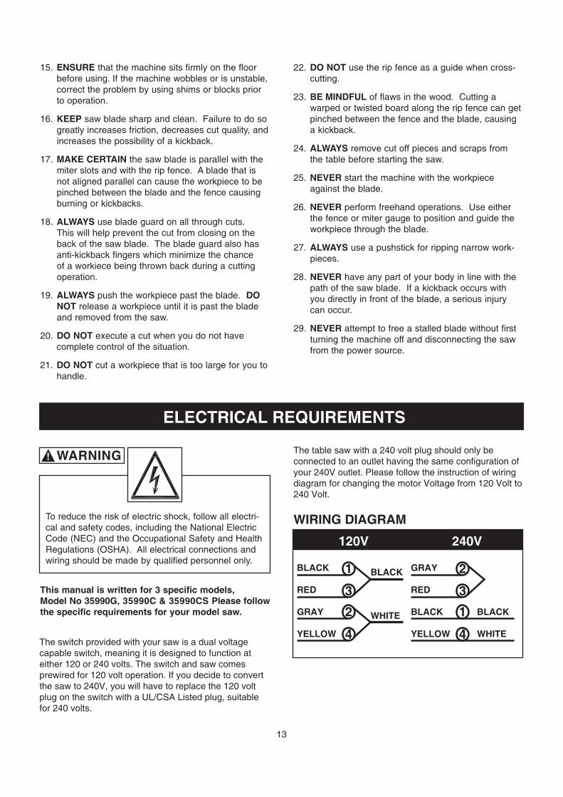
The switch provided with your saw is a dual voltagecapable switch, meaning it is designed to function ateither 120 or 240 volts. The switch and saw comesprewired for 120 volt operation. If you decide to convertthe saw to 240V, you will have to replace the 120 volt plug on the switch with a UL/CSA Listed plug, suitable for 240 volts.
The table saw with a 240 volt plug should only be connected to an outlet having the same configuration ofyour 240V outlet. Please follow the instruction of wiringdiagram for changing the motor Voltage from 120 Volt to240 Volt.
WIRING DIAGRAM
BLACK
RED
GRAY
YELLOW
1
3
2
4
BLACK
WHITE
GRAY
RED
BLACK BLACK
YELLOW WHITE
2
3
1
4
120V 240V

14
GROUNDING INSTRUCTIONS
This machine MUST BE GROUNDED while in use toprotect the operator from electric shock.
In the event of a malfunction or breakdown, GROUND-ING provides the path of least resistance for electriccurrent and reduces the risk of electric shock. The plugMUST be plugged into a matching electrical receptaclethat is properly installed and grounded in accordancewith ALL local codes and ordinances.
If a plug is provided with your machine DO NOT modifythe plug. If it will not fit your electrical receptacle, havea qualified electrician install the proper connections tomeet all electrical codes local and state. All connectionsmust also adhere to all of OSHA mandates.
IMPROPER ELECTRICAL CONNECTION of the equip-ment-grounding conductor can result in risk of electricshock. The conductor with the green insulation (with orwithout yellow stripes) is the equipment-grounding con-ductor. DO NOT connect the equipment-grounding con-ductor to a live terminal if repair or replacement of theelectric cord or plug is necessary.
Check with a qualified electrician or service personnel ifyou do not completely understand the groundinginstructions, or if you are not sure the tool is properlygrounded.
PLUGS/RECEPTACLES
Electrocution or fire could result if this machine isnot grounded properly or if the electrical configura-tion does not comply with local and state electricalcodes.
MAKE CERTAIN the machine is disconnectedfrom power source before starting any electricalwork.
MAKE SURE the circuit breaker does not exceedthe rating of the plug and receptacle.
The motor supplied with your machine is either a115/230 dual voltage motor (Model 35600) or a dedicat-ed 230 volt, single phase motor (Model 35605). Neverconnect the green or ground wire to a live terminal.
The machine should only be connected to an outlethaving the same configuration as the plug.
EXTENSION CORDS
To reduce the risk of fire or electrical shock, use theproper gauge of extension cord. When using anextension cord, be sure to use one heavy enough tocarry the current your machine will draw.
The smaller the gauge-number, the larger the diameterof the extension cord is. If in doubt of the proper size ofan extension cord, use a shorter and thicker cord. Anundersized cord will cause a drop in line voltage result-ing in a loss of power and overheating.
USE ONLY a 3-wire extension cord that has a 3-pronggrounding plug and a 3-pole receptacle that accepts themachine’s plug.
If you are using an extension cord outdoors, be sure itis marked with the suffix “W-A” (“W” in Canada) to indi-cate that it is acceptable for outdoor use.
Make certain the extension cord is properly sized, andin good electrical condition. Always replace a worn ordamaged extension cord immediately or have itrepaired by a qualified person before using it.
Protect your extension cords from sharp objects, exces-sive heat, and damp or wet areas.
CAUTION
MINIMUM RECOMMENDED GAUGE FOR EXTENSION CORDS (AWG)
120 VOLT OPERATION ONLY
25’ LONG 50’ LONG 100’ LONG
0 to 6 Amps 18 AWG 16 AWG 16 AWG6 to 10 Amps 18 AWG 16 AWG 14 AWG
10 to 12 Amps 16 AWG 16 AWG 14 AWG12 to 15 Amps 14 AWG 12 AWG Not
recommended
MINIMUM RECOMMENDED GAUGE FOR EXTENSION CORDS (AWG)
240 VOLT OPERATION ONLY
25’ LONG 50’ LONG 100’ LONG
0 to 6 Amps 18 AWG 18 AWG 16 AWG6 to 10 Amps 18 AWG 18 AWG 14 AWG
10 to 12 Amps 16 AWG 16 AWG 14 AWG12 to 15 Amps 14 AWG 12 AWG Not
recommended
WARNING!
WARNING!
WARNING!
!
UNPACKING & INVENTORY
!
WARNING!
can be removed by spraying WD-40 on them and wip-ing it off with a soft cloth. This may need redone sever-al times before all of the protective coatings areremoved completely.
After cleaning, apply a good quality paste wax to anyunpainted surfaces. Make sure to buff out the waxbefore assembly.
Compare the items to inventory figures; verify that allitems are accounted for before discarding the shippingbox.
If any parts are missing, do not attempt to plug in thepower cord and turn “ON” the machine. The machineshould only be turned “ON” after all the parts have beenobtained and installed correctly. For missing parts,contact Steel City at 1-877-SC4-TOOL.
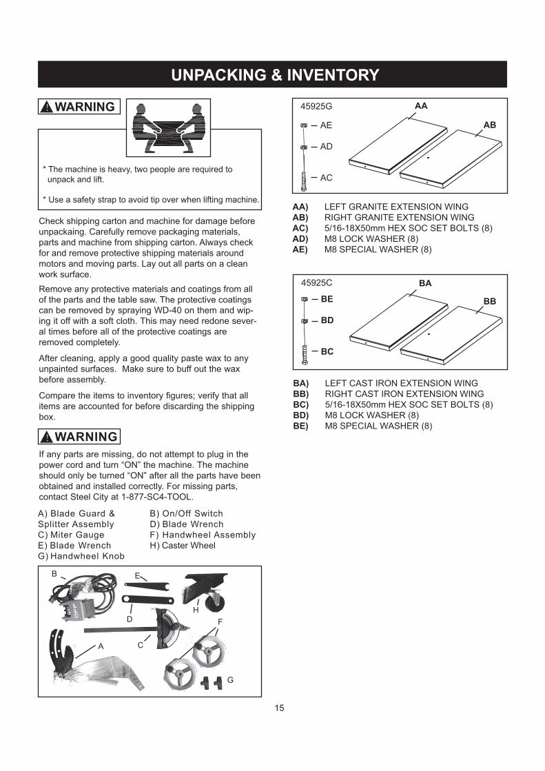
A) Blade Guard &Splitter AssemblyC) Miter GaugeE) Blade WrenchG) Handwheel Knob
B) On/Off SwitchD) Blade WrenchF) Handwheel AssemblyH) Caster Wheel
A
B
C
D
E
G
FH
AA) LEFT GRANITE EXTENSION WINGAB) RIGHT GRANITE EXTENSION WINGAC) 5/16-18X50mm HEX SOC SET BOLTS (8)AD) M8 LOCK WASHER (8)AE) M8 SPECIAL WASHER (8)
AE
AD
AC
AA
BA
45925G
AB
BA) LEFT CAST IRON EXTENSION WINGBB) RIGHT CAST IRON EXTENSION WINGBC) 5/16-18X50mm HEX SOC SET BOLTS (8)BD) M8 LOCK WASHER (8)BE) M8 SPECIAL WASHER (8)
BE
BD
BC
45925C
BB
15
WARNING
Check shipping carton and machine for damage before unpackaing. Carefully remove packaging materials, parts and machine from shipping carton. Always check for and remove protective shipping materials around motors and moving parts. Lay out all parts on a clean work surface.Remove any protective materials and coatings from all of the parts and the table saw. The protective coatings
* The machine is heavy, two people are required to unpack and lift.
* Use a safety strap to avoid tip over when lifting machine.

16
A) M8 FLAT WASHER B) M8 LOCK WASHER C) 5/16-18X50mm HEX ALLEN BOLT
Bag 1. Extension Wing Screw Package
ABC
A) 5/16-18*5/8 HEX SOC HD SCRBag 5. (A) Front/ Back Rail Screw Package
A
Bag 2. Cabinet Leg Assembly Screw Package
AB
C
DEHGF
M8X20mm HEX HD SCR M8 HEX NUT M8 FLAT WASHER M8 LOCK WASHER M8X16mm CARRIAGE BOLT M8X15mm SCR HEX SOC SET SCRM6X16mm HEX SOC HD SCRM6 HEX NUT
A)B)C)D)E)F)G)H)
(8)(16)(22)(22)(16)(10)
(4)(2) A
B
C
M6 FLAT WASHER for 36” Rail M6 LOCK WASHER for 36” Rail M6X16 PAN HD SCR for 36” Rail
Bag 5. (B) Rail Tube Screw Package
!
(8)(8)(8)
(7)
Location
Location
Location
Location
(4)(4)(4)
A)B)C)
OR91084OR90248SC80470
OR90059OR90502SC80111
SC80112
OR93917OR90307OR90311OR90248OR94770OR93380SC80111OR90235
Bag 3. Fence Bracket Package
Bag 4. Switch Screw Package
ABCDE
F
M8X16 CARRIAGE BOLT M8 FLAT WASHER M8 LOCK WASHER M8 HEX NUT M4X8 TAP SCREW
M6 FLAT WASHERM6 LOCK WASHERM6X16 PAN HEAD SCREW
A)B)C)D)E)
G)H)I)
(2)(2)(2)(2)(1)
(2)(2)(2)
Location
OR94770OR90311OR90248OR90307OR91832
OR90059OR90502SC80111
FENCE BRACKETSF) (2)SC10527
G
H
I
Bag 6. Caster Wheel Screw PackageA) M8X16 CARRIAGE BOLT B) M8 HEX FLANGE NUT C) LEVELING SCREW D) M8 HEX NUT
OR94470OR94771SC10529OR90307
(2)(2)(2)(2)
C A
BD
!Bag. 7 Dust Chute / Port Screw PackageA) 1/4-20 X 1/2 ROUND HD TAP SCREWB) M5X12 PAN HEAD SCREW
SC80408OR92137
(4)(4)
A
B! Location Location LocationLocation
Location Location
M6 FLAT WASHER for 52” Rail M6 LOCK WASHER for 52” Rail M6X16 PAN HD SCR for 52” Rail
(6)(6)(6)
A)B)C)
OR90059OR90502SC80111
A
B
C
Location

17
ASSEMBLY
The table saw is a heavy machine; two people maybe required for certain assembly operations.
DO NOT assemble the table saw until you are surethe tool is unplugged.
DO NOT assemble the table saw until you are surethe power switch is in the “OFF” position.
For your own safety, DO NOT connect the machine tothe power source until the machine is completelyassembled and you read and understand this entireUser Manual.
MAKE CERTAIN THAT THE SAW IS DISCONNECT-ED FROM THE POWER SOURCE.
CABINET LEG ASSEMBLY
C
WARNING!
WARNING!
NOTE: Use FIG. 1 as a referencing guide.1. Remove all the doors and panels.2. Lay the saw on back. CAUTION: The table saw is heavy; two people are required for this operation. Be sure to lay cardboard on the floor to protect the table and cabinet. Use wedge to have an angle.3. Install Primary Dust Chute and the 4” Dust Adapter Port.
4. Attach four leg assemblies (A) to the cabinet by using 8 of each: Soc Screws, Nuts, Lock Washers and Flat Washers. Do not completely tighten hardware at this time.5. Attach two U-shape front/ back panels by using 4 of each: Carriage Screws, Lock and Flat Washers.
Fig. 1
L
C
F
L
K
D
A
BJ
E
H
I
G
6. Attach Wheel Kit by using Pan Head Allen Screws (10) and Flat Washers (2) on bottom of Legs.7. Attach Corss Brace by using M6x16mm Pan Head Screws (4) and Lock Washers.8. Attach the Flip Wheel to the cross bracket by using Carriage Screws (2) and Lock Nuts (2).9. Attach two Leveling Feet with Nuts (2).10. Tighten all hardware, starting at cabinet. With help, place machine upright. SEE FIG. 2
HANDWHEEL ASSEMBLY
1. Place one of the handwheels (A) onto the blade raise/lower shaft (B) located on the front of the cabinet. Align the groove in the back of the handwheel with the pin (C). SEE FIG. 3
MAKE CERTAIN THAT THE SAW IS DISCONNECT-ED FROM THE POWER SOURCE.
WARNING!
Fig. 3
A
CB

19
Fig. 8
Fig. 9
Fig. 7
B
C
20
FENCE & RAIL ASSEMBLY PROCEDURES
MAKE CERTAIN THAT THE SAW IS DISCONNECT-ED FROM THE POWER SOURCE.
WARNING!
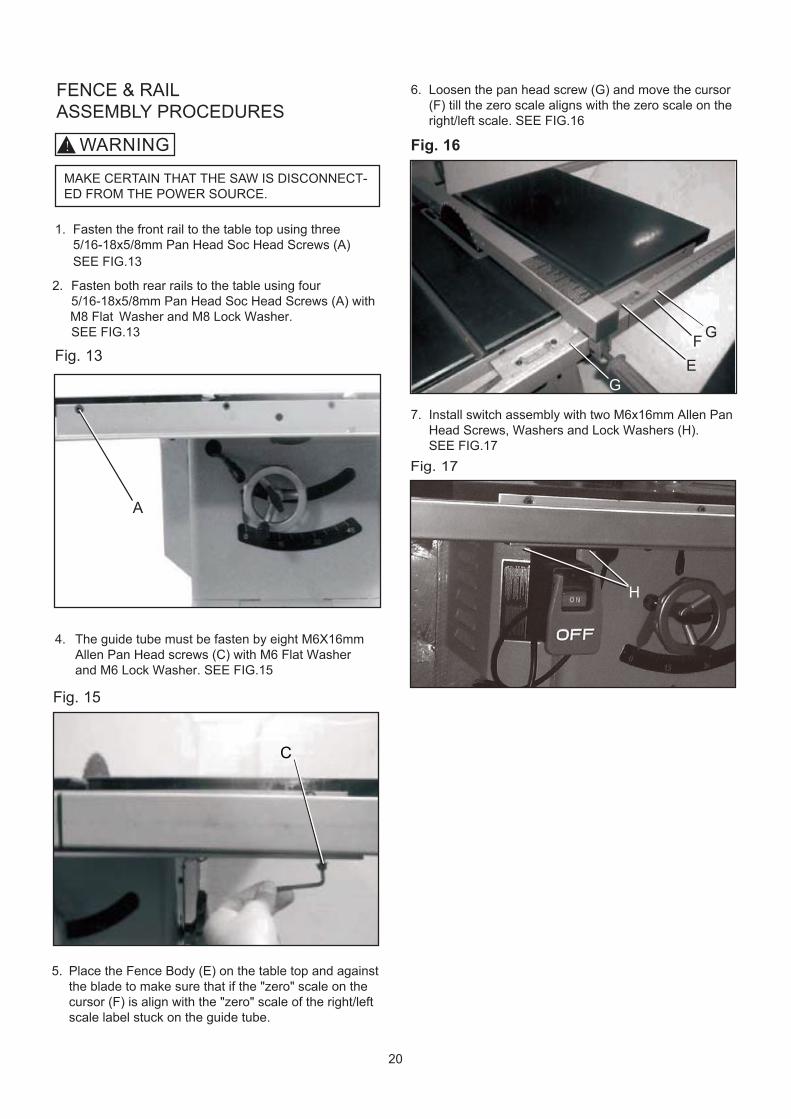
1. Fasten the front rail to the table top using three 5/16-18x5/8mm Pan Head Soc Head Screws (A)
SEE FIG.13
2. Fasten both rear rails to the table using four 5/16-18x5/8mm Pan Head Soc Head Screws (A) with M8 Flat Washer and M8 Lock Washer.
SEE FIG.13
4. The guide tube must be fasten by eight M6X16mm Allen Pan Head screws (C) with M6 Flat Washer and M6 Lock Washer. SEE FIG.15
5. Place the Fence Body (E) on the table top and against the blade to make sure that if the "zero" scale on the cursor (F) is align with the "zero" scale of the right/left scale label stuck on the guide tube.
6. Loosen the pan head screw (G) and move the cursor (F) till the zero scale aligns with the zero scale on the right/left scale. SEE FIG.16
7. Install switch assembly with two M6x16mm Allen Pan Head Screws, Washers and Lock Washers (H). SEE FIG.17
Fig. 13
A
Fig. 15
Fig. 16
EG
F G
Fig. 17
H
C

21
B
A
Fig. 18
Fig. 19
CONNECTING SWITCH CORD TOMOTOR CORD
1. Place the switch cord (A) through hole (B) in front of Cabinet. SEE FIG. 18
2. Open motor cover, insert three prong switch cord (C) into three hole outlet (D) of the motor cord. SEE FIG. 19
3. Pull slack in switch cord into the cabinet. Make sure that the power cord inside of the cabinet is properly routed and clear of the saw blade and any pinch points for all blade height and blade angle settings.
INSTALLATION AND LEVELING
Final location for the saw must be level, dry, well lighted,and have enough room to allow movement around the msaw with long pieces of wood stock.
Level the saw front to back and side to side, using acarpenter’s level placed on the table. Use shims underthe corners, if necessary, but make sure the saw isstable before being placed into service.
MAKE CERTAIN THAT THE SAW IS DISCONNECT-ED FROM THE POWER SOURCE.
WARNING!

22
RIVING KNIFE / SPLITTER COMPONENTS ASSEMBLY
BLADE ASSEMBLY
MAKE CERTAIN THAT THE SAW IS DISCONNECT-ED FROM THE POWER SOURCE.
WARNING!
NOTE: Remove the table insert (Table insert are gripped by four magnets on the table).
Fig. 20
C
Fig. 22
Fig. 22
INSTALLING AND REMOVINGTHE RIVING KNIFE / SPLITTER
To Install:
1. Loosen the knob by pulling upwards (C), Line up the riving knife/splitter in the proper direction to the mounting bracket (B). SEE FIG. 21
2. Push the Riving Knife/ Splitter all the way down into the mounting bracket, make sure the location pin is properly locked in the hole of the Riving Knife/ Splitter. (The location hole is on the button side of the Riving Knife/ Splitter ).
3. Tighten the fasting knob by lowering down (C). SEE FIG. 22
To Remove:
1. Loosen the fasten knob (C). SEE FIG. 22
2. Remove the Riving Knife/ splitter out of mounting bracket (B). SEE FIG. 22
NOTE: Make sure blade or arbor is at the highest position before adding or removing the riving Knife/ Splitter.
MAKE CERTAIN THAT THE SAW IS DISCONNECT-ED FROM THE POWER SOURCE.
WARNING!
Fig. 23
CB
C
MKLJZ
L
23
MAKE CERTAIN THAT THE SAW IS DISCONNECT-ED FROM THE POWER SOURCE.
WARNING!
N Q
Fig. 24
Fig. 26
Fig. 27
Fig. 25
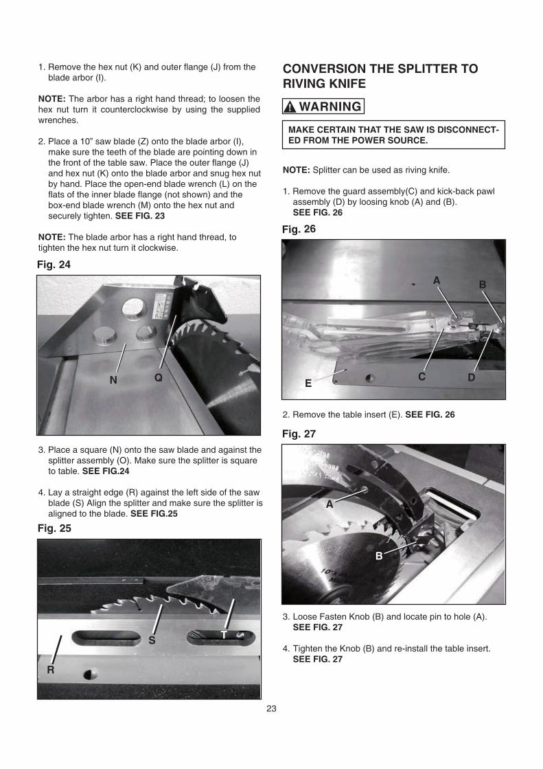
1. Remove the hex nut (K) and outer flange (J) from the blade arbor (I).
NOTE: The arbor has a right hand thread; to loosen the hex nut turn it counterclockwise by using the supplied wrenches.
2. Place a 10” saw blade (Z) onto the blade arbor (I), make sure the teeth of the blade are pointing down in the front of the table saw. Place the outer flange (J) and hex nut (K) onto the blade arbor and snug hex nut by hand. Place the open-end blade wrench (L) on the flats of the inner blade flange (not shown) and the box-end blade wrench (M) onto the hex nut and securely tighten. SEE FIG. 23
NOTE: The blade arbor has a right hand thread, totighten the hex nut turn it clockwise.
\
3. Place a square (N) onto the saw blade and against the splitter assembly (O). Make sure the splitter is square to table. SEE FIG.24
4. Lay a straight edge (R) against the left side of the saw blade (S) Align the splitter and make sure the splitter is aligned to the blade. SEE FIG.25
CONVERSION THE SPLITTER TO RIVING KNIFE
NOTE: Splitter can be used as riving knife.
1. Remove the guard assembly(C) and kick-back pawl assembly (D) by loosing knob (A) and (B).
SEE FIG. 26
2. Remove the table insert (E). SEE FIG. 26
3. Loose Fasten Knob (B) and locate pin to hole (A).SEE FIG. 27
4. Tighten the Knob (B) and re-install the table insert. SEE FIG. 27
A
CE
A
B
D
B
R
S T
24
ADJUSTMENTS
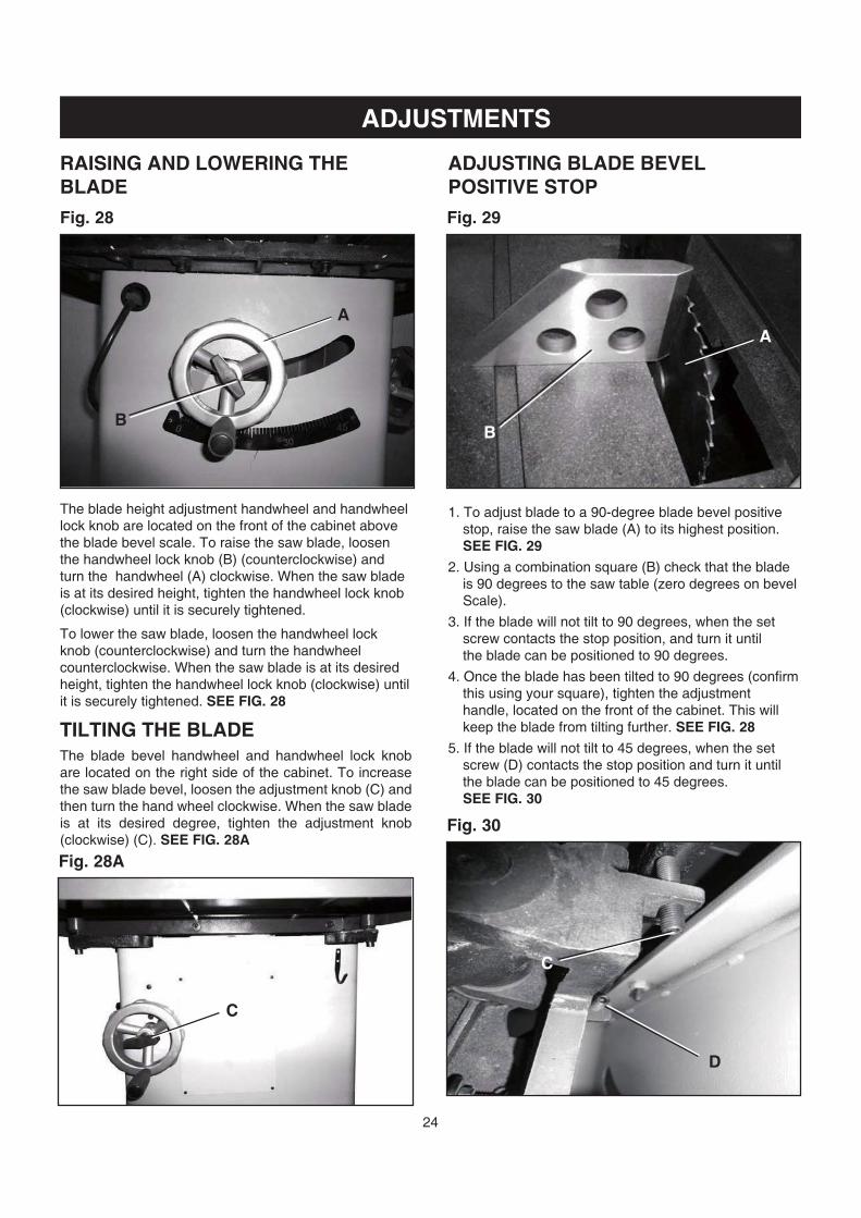
RAISING AND LOWERING THE BLADE
The blade height adjustment handwheel and handwheellock knob are located on the front of the cabinet above the blade bevel scale. To raise the saw blade, loosen the handwheel lock knob (B) (counterclockwise) and turn the handwheel (A) clockwise. When the saw blade is at its desired height, tighten the handwheel lock knob(clockwise) until it is securely tightened.
To lower the saw blade, loosen the handwheel lock knob (counterclockwise) and turn the handwheelcounterclockwise. When the saw blade is at its desiredheight, tighten the handwheel lock knob (clockwise) until it is securely tightened. SEE FIG. 28
TILTING THE BLADEThe blade bevel handwheel and handwheel lock knob are located on the right side of the cabinet. To increase the saw blade bevel, loosen the adjustment knob (C) and then turn the hand wheel clockwise. When the saw blade is at its desired degree, tighten the adjustment knob (clockwise) (C). SEE FIG. 28A
Fig. 28
C
Fig. 28A
ADJUSTING BLADE BEVEL POSITIVE STOP
1. To adjust blade to a 90-degree blade bevel positive stop, raise the saw blade (A) to its highest position.
SEE FIG. 29
2. Using a combination square (B) check that the blade is 90 degrees to the saw table (zero degrees on bevel Scale).
3. If the blade will not tilt to 90 degrees, when the set screw contacts the stop position, and turn it until the blade can be positioned to 90 degrees.
4. Once the blade has been tilted to 90 degrees (confirm this using your square), tighten the adjustment handle, located on the front of the cabinet. This will keep the blade from tilting further. SEE FIG. 28
5. If the blade will not tilt to 45 degrees, when the set screw (D) contacts the stop position and turn it until the blade can be positioned to 45 degrees. SEE FIG. 30
Fig. 29
Fig. 30
BB
AA
C
D
25
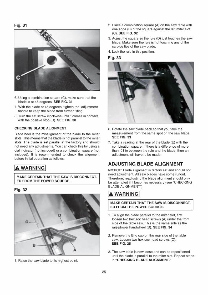
6. Using a combination square (C), make sure that the blade is at 45 degrees. SEE FIG. 31
7. With the blade at 45 degrees, tighten the adjustment handle to keep the blade from further tilting.
8. Turn the set screw clockwise until it comes in contact with the positive stop (D). SEE FIG. 30
CHECKING BLADE ALIGNMENT
Blade heel is the misalignment of the blade to the miter slots. This means that the blade is not parallel to the miter slots. The blade is set parallel at the factory and should not need any adjustments. You can check this by using a dial indicator (not included) or a combination square (not included). It is recommended to check the alignment before initial operation as follows:
1. Raise the saw blade to its highest point.
2. Place a combination square (A) on the saw table with one edge (B) of the square against the left miter slot (C). SEE FIG. 32
3. Adjust the square so the rule (D) just touches the saw blade. Make sure the rule is not touching any of the carbide tips of the saw blade.
4. Lock the rule in this position.
6. Rotate the saw blade back so that you take the measurement from the same spot on the saw blade.
SEE FIG. 33
7. Take a reading at the rear of the blade (E) with the combination square. If there is a difference of more than. 01 in between the rule and the blade, then an adjustment will have to be made.
ADJUSTING BLADE ALIGNMENTNOTICE: Blade alignment is factory set and should notneed adjustment. All saw blades have some runout.Therefore, readjusting the blade alignment should only be attempted if it becomes necessary (see "CHECKINGBLADE ALIGNMENT")
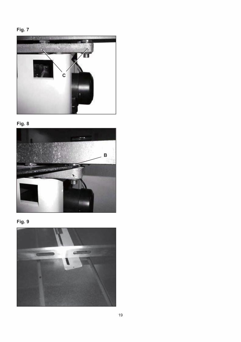
1. To align the blade parallel to the miter slot, first loosen two hex soc head screws (A) under the front side of the table saw. This is the same side as the raise/lower handwheel (B). SEE FIG. 34
2. Remove the End cap on the rear side of the table saw, Loosen two hex soc head screws (C).
SEE FIG. 35
3. The saw table is now loose and can be repositioned until the blade is parallel to the miter slot. Repeat steps in “CHECKING BLADE ALIGNMENT."
MAKE CERTAIN THAT THE SAW IS DISCONNECT-ED FROM THE POWER SOURCE.
WARNING!
MAKE CERTAIN THAT THE SAW IS DISCONNECT-ED FROM THE POWER SOURCE.
WARNING!
Fig. 31
Fig. 33
Fig. 32
26
ADJUSTMENTS
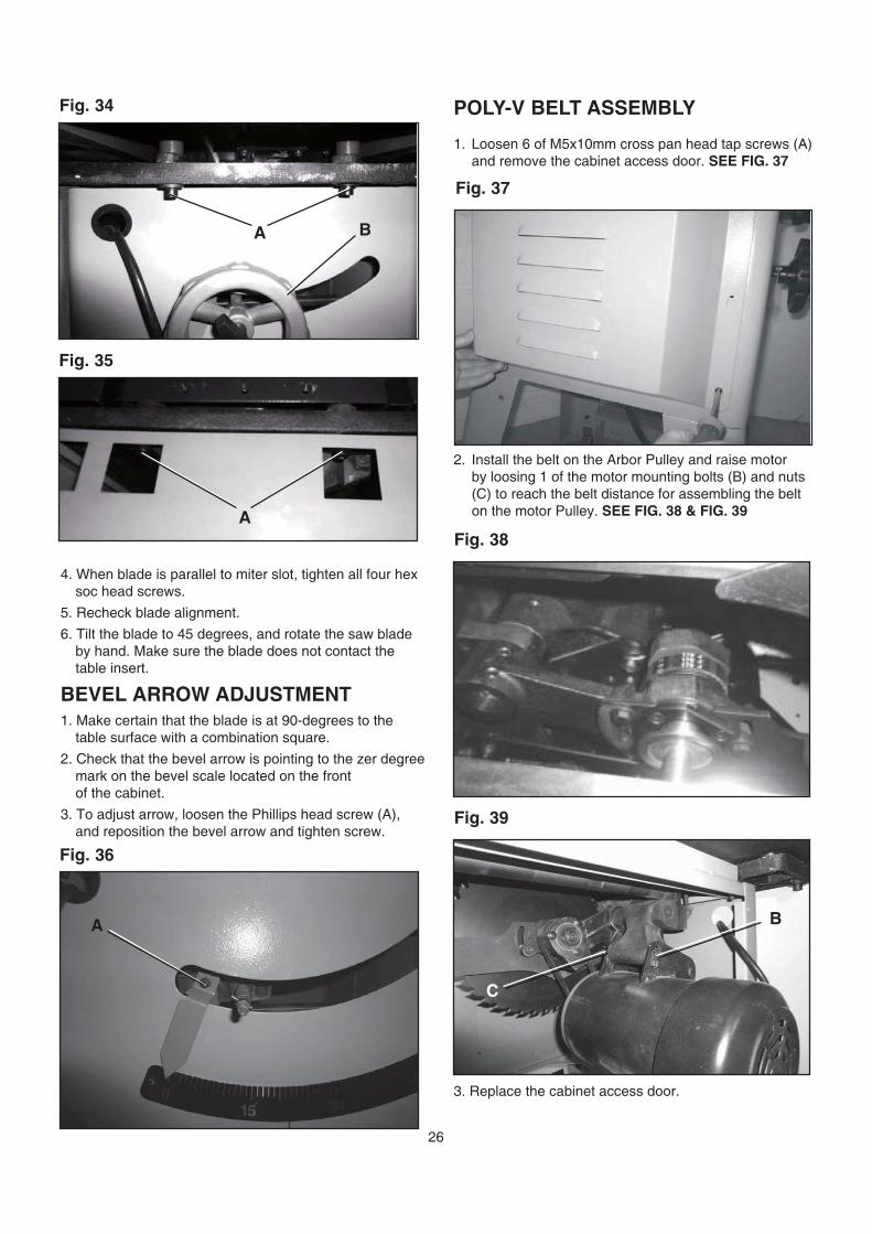
4. When blade is parallel to miter slot, tighten all four hex soc head screws.
5. Recheck blade alignment.
6. Tilt the blade to 45 degrees, and rotate the saw blade by hand. Make sure the blade does not contact the table insert.
BEVEL ARROW ADJUSTMENT 1. Make certain that the blade is at 90-degrees to the table surface with a combination square.
2. Check that the bevel arrow is pointing to the zer degree mark on the bevel scale located on the front of the cabinet.
3. To adjust arrow, loosen the Phillips head screw (A), and reposition the bevel arrow and tighten screw.
POLY-V BELT ASSEMBLY
1. Loosen 6 of M5x10mm cross pan head tap screws (A) and remove the cabinet access door. SEE FIG. 37
2. Install the belt on the Arbor Pulley and raise motor by loosing 1 of the motor mounting bolts (B) and nuts (C) to reach the belt distance for assembling the belt on the motor Pulley. SEE FIG. 38 & FIG. 39
3. Replace the cabinet access door.
A
Fig. 36
Fig. 35
A
Fig. 34
A B
Fig. 37
Fig. 38
Fig. 39
B
C
27
ADJUSTMENTSTABLE INSERT ADJUSTMENT
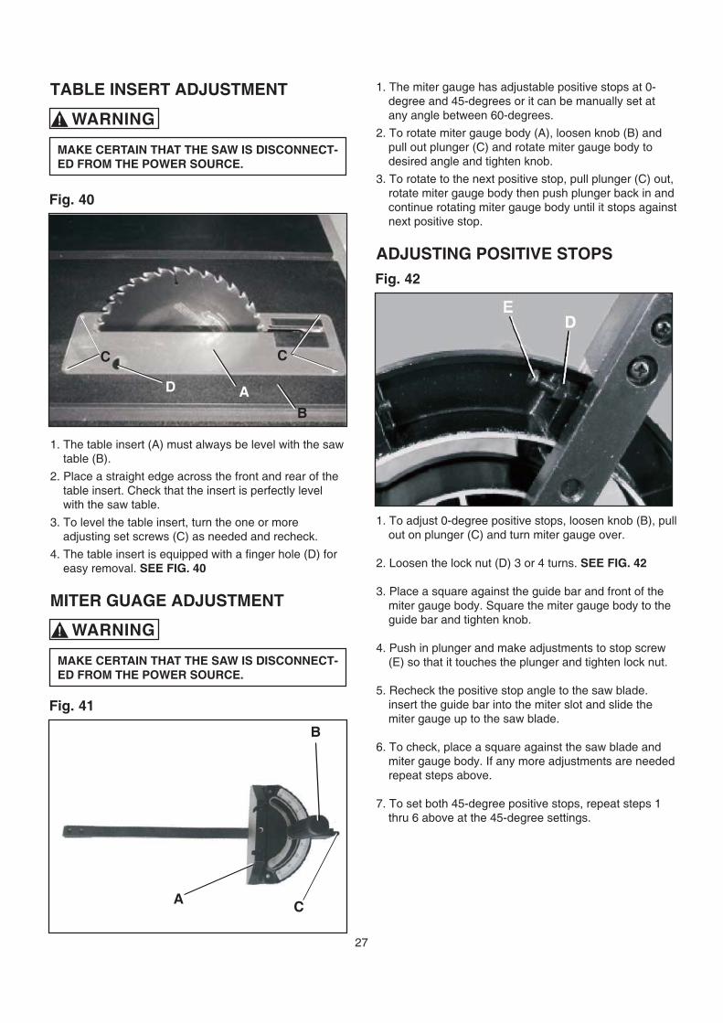
1. The table insert (A) must always be level with the saw table (B).
2. Place a straight edge across the front and rear of the table insert. Check that the insert is perfectly level with the saw table.
3. To level the table insert, turn the one or more adjusting set screws (C) as needed and recheck.
4. The table insert is equipped with a finger hole (D) for easy removal. SEE FIG. 40
MITER GUAGE ADJUSTMENT
v
in “CHECKING BLADE ALIGNMENT."
1. The miter gauge has adjustable positive stops at 0- degree and 45-degrees or it can be manually set at any angle between 60-degrees.
2. To rotate miter gauge body (A), loosen knob (B) and pull out plunger (C) and rotate miter gauge body to desired angle and tighten knob.
3. To rotate to the next positive stop, pull plunger (C) out, rotate miter gauge body then push plunger back in and continue rotating miter gauge body until it stops against next positive stop.
ADJUSTING POSITIVE STOPS
1. To adjust 0-degree positive stops, loosen knob (B), pull out on plunger (C) and turn miter gauge over.
2. Loosen the lock nut (D) 3 or 4 turns. SEE FIG. 42
3. Place a square against the guide bar and front of the miter gauge body. Square the miter gauge body to the guide bar and tighten knob.
4. Push in plunger and make adjustments to stop screw (E) so that it touches the plunger and tighten lock nut.
5. Recheck the positive stop angle to the saw blade. insert the guide bar into the miter slot and slide the miter gauge up to the saw blade.
6. To check, place a square against the saw blade and miter gauge body. If any more adjustments are needed repeat steps above.
7. To set both 45-degree positive stops, repeat steps 1 thru 6 above at the 45-degree settings.
Fig. 40
Fig. 42
Fig. 41
MAKE CERTAIN THAT THE SAW IS DISCONNECT-ED FROM THE POWER SOURCE.
WARNING!
MAKE CERTAIN THAT THE SAW IS DISCONNECT-ED FROM THE POWER SOURCE.
WARNING!
C
D A
B
C
A C
B
28
OPERATIONS
A separate electrical circuit should be used for yourtable saw. The circuit should not be less than #14AWG wire and should be protected with a 15-amptime lag fuse.
Have a qualified electrician repair or replace damagedor worn cord immediately.
Before connecting the motor to the power line, makecertain the switch is in the “OFF” position and be surethat the electric current is of the same characteristicsas the motor nameplate. All line connections shouldmake good contact.
Running on low voltage or long extension cords willdamage the motor.
DO NOT expose the table saw to rain or operate thein damp locations.
MAKE SURE all parts have been assembled correct-ly and are in working order.
KEEP table surface clear of tools and debris beforestarting table saw.
4. When the table saw is not in use, the “ON” buttonshould be locked so that it cannot be started.
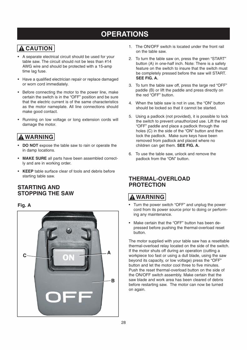
5. Using a padlock (not provided), it is possible to lockthe switch to prevent unauthorized use. Lift the red“OFF” paddle and place a padlock through theholes (C) in the side of the “ON” button and thenlock the padlock. Make sure keys have beenremoved from padlock and placed where nochildren can get them. SEE FIG. A.
6. To use the table saw, unlock and remove thepadlock from the “ON” button.
THERMAL-OVERLOADPROTECTION
Turn the power switch “OFF” and unplug the powercord from its power source prior to doing or perform-ing any maintenance.
Make certain that the “OFF” button has been de-pressed before pushing the thermal-overload resetbutton.
The motor supplied with your table saw has a resettablethermal-overload relay located on the side of the switch.If the motor shuts off during an operation (cutting aworkpiece too fast or using a dull blade, using the sawbeyond its capacity, or low voltage) press the “OFF”button and let the motor cool three to five minutes.Push the reset thermal-overload button on the side ofthe ON/OFF switch assembly. Make certain that thesaw blade and work area has been cleared of debrisbefore restarting saw. The motor can now be turnedon again.
1. The ON/OFF switch is located under the front railon the table saw.
2. To turn the table saw on, press the green “START”button (A) in one-half inch. Note: There is a safetyfeature on the switch to insure that the switch mustbe completely pressed before the saw will START.SEE FIG. A.
3. To turn the table saw off, press the large red “OFF”paddle (B) or lift the paddle and press directly onthe red “OFF” button.
STARTING ANDSTOPPING THE SAW
Fig. A
A
B
C
WARNING!
WARNING!
CAUTION!
29
MAKE CERTAIN THAT THE SAW IS DISCONNECT-ED FROM THE POWER SOURCE.
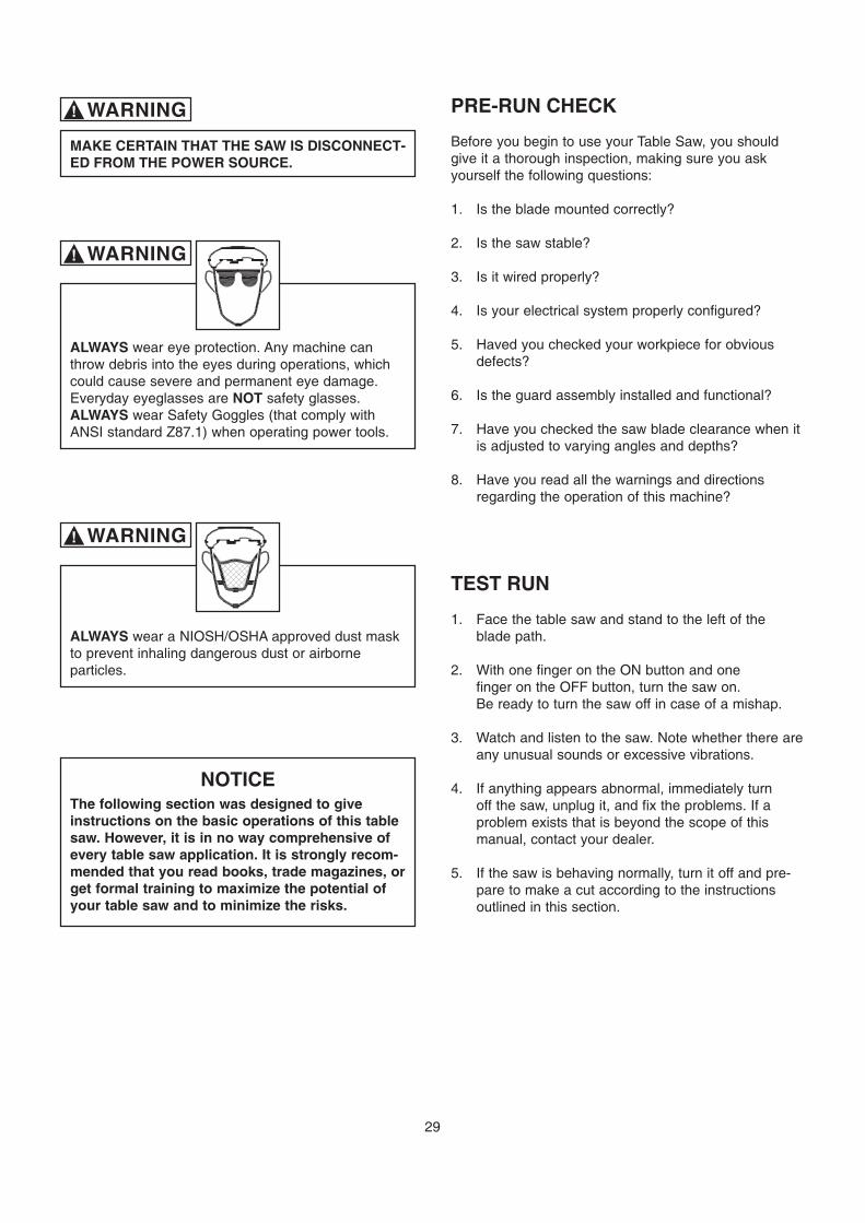
ALWAYS wear eye protection. Any machine canthrow debris into the eyes during operations, whichcould cause severe and permanent eye damage.Everyday eyeglasses are NOT safety glasses.ALWAYS wear Safety Goggles (that comply withANSI standard Z87.1) when operating power tools.
NOTICEThe following section was designed to giveinstructions on the basic operations of this tablesaw. However, it is in no way comprehensive ofevery table saw application. It is strongly recom-mended that you read books, trade magazines, orget formal training to maximize the potential ofyour table saw and to minimize the risks.
PRE-RUN CHECK
Before you begin to use your Table Saw, you shouldgive it a thorough inspection, making sure you askyourself the following questions:
1. Is the blade mounted correctly?
2. Is the saw stable?
3. Is it wired properly?
4. Is your electrical system properly configured?
5. Haved you checked your workpiece for obviousdefects?
6. Is the guard assembly installed and functional?
7. Have you checked the saw blade clearance when itis adjusted to varying angles and depths?
8. Have you read all the warnings and directionsregarding the operation of this machine?
TEST RUN
1. Face the table saw and stand to the left of theblade path.
2. With one finger on the ON button and onefinger on the OFF button, turn the saw on.Be ready to turn the saw off in case of a mishap.
3. Watch and listen to the saw. Note whether there areany unusual sounds or excessive vibrations.
4. If anything appears abnormal, immediately turnoff the saw, unplug it, and fix the problems. If aproblem exists that is beyond the scope of thismanual, contact your dealer.
5. If the saw is behaving normally, turn it off and pre-pare to make a cut according to the instructionsoutlined in this section.
ALWAYS wear a NIOSH/OSHA approved dust maskto prevent inhaling dangerous dust or airborneparticles.
WARNING!
WARNING!
WARNING!

30
BLADE SELECTIONChoosing the correct blade for the job is essential forthe safe and efficient use of your table saw. Ignoringthis important step could result in damage to the sawand serious injury to the operator. Below are the mostcommon saw blades and their uses.
1. Rip Blade: Used for cutting with the grain.Typically, 10” rip blades have between 18-40 teethand large gullets to allow for large chip removal.SEE FIG. 31.
Fig. 31
Fig. 32
Fig. 33
2. Cross-cut Blade: Used for cutting across the grain.10” cross-cut blades have between 60-80 teeth anda shallow gullet. SEE FIG. 32.
3. Combination Blade: Used for cutting with andacross the grain. A compromise between a rip bladeand a cross-cut blade, a 10” combination blade willtypically have between 40-50 teeth. SEE FIG. 33.
4. Thin-kerf: Most types of saw blades are availablein a thin-kerf style. Designed primarily to minimizestock waste, thin-kerf blades are used in conjunc-tion with a blade stabilizer to reduce blade wobble.Note: Many blade guards/splitters are thicker thanmany thin-kerf blades. Make sure that the stock willpass by the guard/splitter before beginning a cut.
5. Dado Blades: There are two types of dado blades:stack and wobble. Stack dadoes involve more set-up time, but they provide a superior finish cut whencompared to a wobble dado.
6. Moulding Heads: A moulding head is a cutterheadthat attaches to the arbor and holds individualmoulding knives. They are very dangerous andrequire training beyond the scope of this manual.
This section on blade selection is by no means compre-hensive. Always follow the saw blade manufacturer’srecommendations to assure safe and efficient operationof your table saw.
31
CROSSCUTTINGCrosscutting means cutting across the grain of thewood. In wood products without grain (i.e. MDF,particleboard), crosscutting simply means cutting acrossthe width of the stock.
Crosscuts are made with the miter gauge. There aretwo miter gauge slots in the table top. Use the one thatworks best for the piece being crosscut. To make acrosscut using the miter gauge:
1. Inspect the board for soundness. You do notnecessarily need a square edge to crosscut withaccuracy.
2. Inspect the miter gauge. Is it properly set and tight?Move the rip fence completely out of the way.
3. Turn on the saw and allow it to come to full speed.
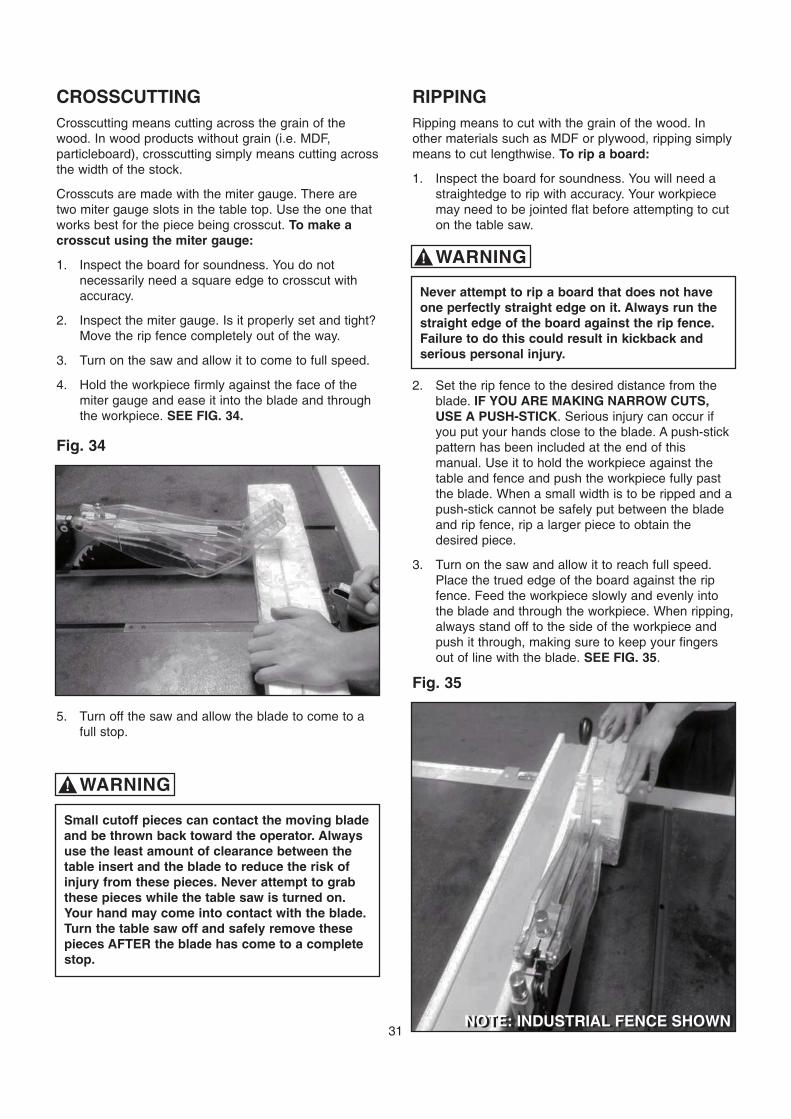
4. Hold the workpiece firmly against the face of themiter gauge and ease it into the blade and throughthe workpiece. SEE FIG. 34.
Fig. 34
Small cutoff pieces can contact the moving bladeand be thrown back toward the operator. Alwaysuse the least amount of clearance between thetable insert and the blade to reduce the risk ofinjury from these pieces. Never attempt to grabthese pieces while the table saw is turned on.Your hand may come into contact with the blade.Turn the table saw off and safely remove thesepieces AFTER the blade has come to a completestop.
RIPPINGRipping means to cut with the grain of the wood. Inother materials such as MDF or plywood, ripping simplymeans to cut lengthwise. To rip a board:
1. Inspect the board for soundness. You will need astraightedge to rip with accuracy. Your workpiecemay need to be jointed flat before attempting to cuton the table saw.
Never attempt to rip a board that does not haveone perfectly straight edge on it. Always run thestraight edge of the board against the rip fence.Failure to do this could result in kickback andserious personal injury.
Fig. 35
WARNING!
WARNING!
5. Turn off the saw and allow the blade to come to afull stop.
2. Set the rip fence to the desired distance from theblade. IF YOU ARE MAKING NARROW CUTS,USE A PUSH-STICK. Serious injury can occur ifyou put your hands close to the blade. A push-stickpattern has been included at the end of thismanual. Use it to hold the workpiece against thetable and fence and push the workpiece fully pastthe blade. When a small width is to be ripped and apush-stick cannot be safely put between the bladeand rip fence, rip a larger piece to obtain thedesired piece.
3. Turn on the saw and allow it to reach full speed.Place the trued edge of the board against the ripfence. Feed the workpiece slowly and evenly intothe blade and through the workpiece. When ripping,always stand off to the side of the workpiece andpush it through, making sure to keep your fingersout of line with the blade. SEE FIG. 35.
NOTE: INDUSTRIAL FENCE SHOWNNOTE: INDUSTRIAL FENCE SHOWN

32
Fig. 36
Stand out of the line of potential kickback. Holdthe workpiece firmly against the fence and table.Do not allow your fingers to get close to theblade! Do not reach over the blade to off-load theworkpiece.
DADO OPERATIONSIn addition to its ability to rip and crosscut lumber,the table saw is also an invaluable tool for creating avariety of dadoes. These non-through cuts can becreated with specially-designed stacking or wobblingdado blades.
Never allow hands or arms to be above or behindthe saw blade. Should kickback occur, the handsand arms can be pulled into the saw blade.Serious injury will result.
Never perform a through cut operation with adado blade. A dado blade was designed to makenon-through cuts only. Failure to follow thesedierctions could result in serious injury.
Dado operations present very real hazardsrequiring proper procedures to avoid seriousinjury. The chance of kickback is always greaterwhen dado blades are used so extra precautionsmust be used. Any movement of the stock awayfrom the fence will cause kickback. Be certainthat stock is flat and straight. Failure to followthese warnings could result in serious personalinjury.
Always use push sticks, featherboards, push pad-dles and other safety accessories whenever poss-ible to increase safety and control during opera-tions which require the blade guard and splitter tobe removed from the saw. ALWAYS replace theblade guard after dadoing is complete.
Proper dado operations will differ depending on theblade system you choose. Consult the instructionsincluded with your dado blades for directions regardingattachment and adjustment. To use a dado blade:
MAKE CERTAIN THAT THE SAW IS DISCONNECT-ED FROM THE POWER SOURCE.
Do not stand directly behind the workpiece whenripping. SEE FIG. 36.
WARNING!
WARNING!
WARNING!
WARNING!
WARNING!
CAUTION!
1. Remove the table insert, splitter guard, and regularsaw blade.
2. Attach and adjust the dado blade system as recom-mended in the dado blade’s instructions.
3. Install the dado table insert.
4. Raise the blade system up to the desired depth ofthe dado. Make sure the dado blade will not cutthrough the workpiece.
5. If dadoing along the length of your workpiece,adjust the distance between the fence and theinside edge of the blade to suit your needs. Whencutting across the wood grain, use the miter gaugeas a guide while dadoing. Remember: Never usethe fence as a stop in conjunction with your mitergauge.
6. Reconnect the saw to the power source.
7. Using a scrap piece as a test piece, switch on thesaw and take a pass over the dado blade.
8. If the cut is satisfactory, repeat with your finishstock.
33
MAINTAINENCEPROTECTING CAST IRON TABLEFROM RUST
The environment and frequency of human contact canhave a very detrimental impact on unpainted cast ironsurface. Moisture, humidity and oils (from human hands!)can cause the unpainted cast iron surfaces to mar or rust,so it is important to conduct routine maintenance to keep your table saw looking new. Cleaning and waxing thecast iron surfaces on a regular maintenance schedule isrecommended as follows:
To clean and maintain the unpained cast iron surfaces:
cast iron surface.
ground cast iron as a flaw, defect or scratches.
surfaces until the stains or rust is removed. Mak sure
scratching or marring the cast iron surface.
oil and dirt from the table saw using a soft cloth or rag.
to all unpainted cast iron surfaces. This will help toprotect the saw from rusting from further contact withmoisture or oily hands.
This table saw requires very little maintenance other thanminor lubrication and cleaning. The following sectionsdetail what will need to be done in order to assurecontinued operation of your saw.
LUBRICATIONThe table saw has sealed lubricated bearings in themotor housing that do not require any additionallubrication from the operator.
trunnions and apply a white lithium grease to keep themlubricated.
MAKE CERTAIN THAT THE SAW IS DISCONNECT-ED FROM THE POWER SOURCE.
WARNING!
Be sure to wear protective eyewear and dust maskwhen cleaning out the cabinet of the saw.
WARNING!
Fig. 38
CLEANING
Keep the inside of the cabinet clear of saw dust and wood
inside of the cabinet or blow out the inside with an air
as high pressure air may damage insulation.
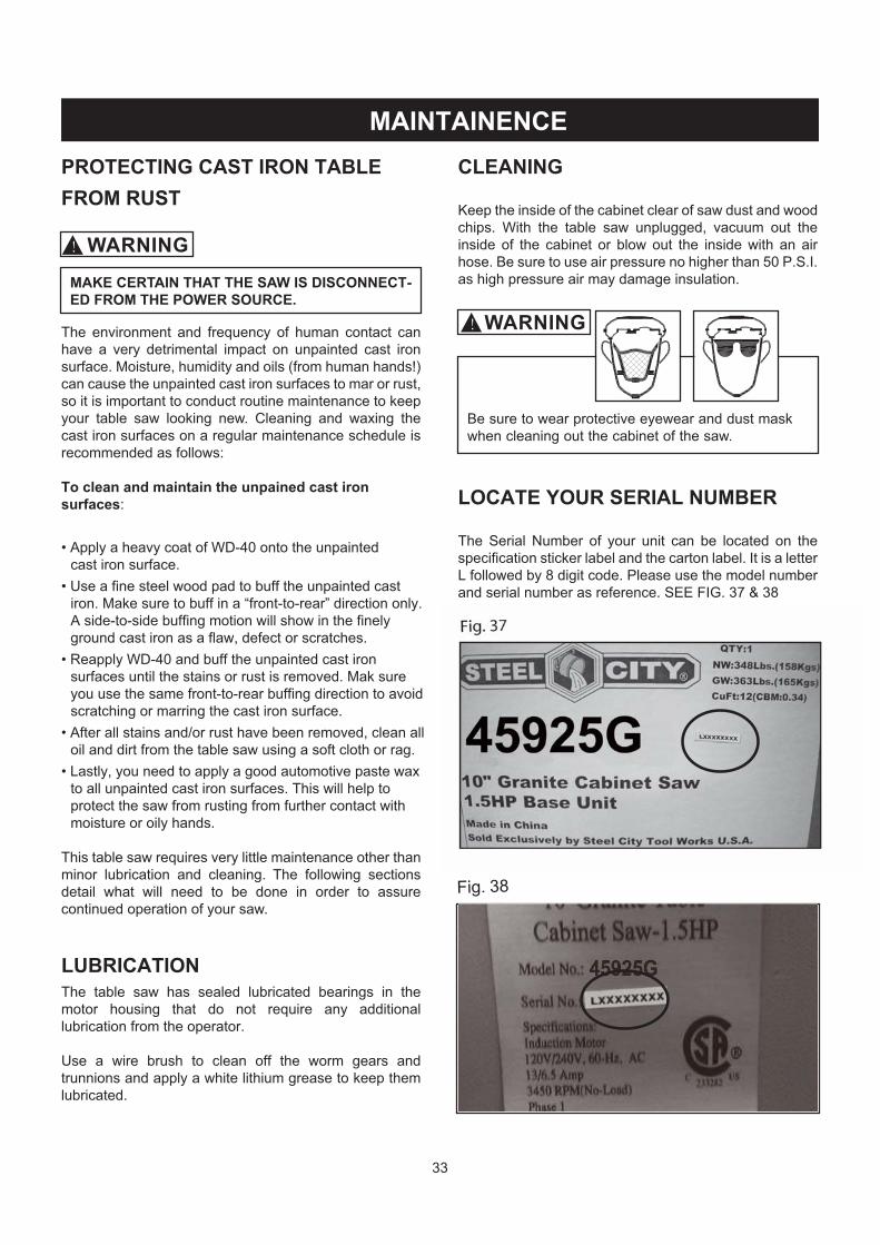
LOCATE YOUR SERIAL NUMBER
and serial number as reference.

34
� NOTES �

PARTS
35
KeyNo.
Part No. Description Q'ty KeyNo.
Part No. Description Q'ty
1 SC10464 RIGHT BLADE GUARD 1 18 SC10475 RIGHT ANTI KICKBACK FINGER 1
2 SC10465 SHOULDERED SCR 2 19 SC10476 TWIST SPRING 1
3 SC10466 ROUND PIN 1 2 20 SC84302 SPRING PIN 3x30 1
4 SC80439 ROUND HD CUTTING SCR M4x10 1 21 SC10477 LEFT ANTI KICKBACK FINGER 1
5 SC80318 HEX SOC SET SCR W/FLAT POINT M4x6 2 22 SC10478 ANTI KICKBACK FINGER SUPPORT 1
6 SC10467 BLADE GUARD SUPPORT ARM 1 23 SC10479 SPECIAL BOLT (LEFT) 1
6A SC76039 WARNING LABEL 1 24 SC10480 SPRING 2 1
7 SC80319 HEX SOC SET SCR W/CONE POINT M5x12 1 25 SC10481 FAST NUT BASE 1
8 SC10468 FIXED SHAFT 2 26 SC10482 RIVING KNIFE PLATE 1
9 SC10469 STEEL BALL 7/32 2 27 SC10483 RIVING KNIFE SUPPORT 1
10 SC10470 SPRING1 2 28 OR93372 HEX SOC HD CAP SCR M6x12 2
11 SC10471 BUSHING 2 29 OR90502 LOCK WASHER M6 2
13 SC10472 TWIST GRIP 2 29A SC80321 HEX SOC SET SCR W/FLAT POINT M6x8 1
14 SC10473 LEFT BLADE GUARD 1 29C SC81113 BLOCKING NUT M8 (LEFT) 2
15 OR95116COUNTERSUNK HD SCR W/CROSSRECESS M4x8
1 29D SC80322 HEX SOC SET SCR W/FLAT POINT M5x10 1
16 SC10474 RIVING KNIFE 2.3mm 1 29E SC80437 CROSS COUNTERSUNK HD TAP SCRST2.9x6.5
2
17 OR94858 CIRCLIPS FOR SHAFT 12 2 29F SC10484ANTI KICKBACK FINGER SUPPORTBEARER
2

36
KeyNo.
Part No. Description Q'ty KeyNo.
Part No. Description Q'ty
41 OR91789 NYLON SET SCR 1/4-28x3/8" 4 69 OR90362 EXT TOOTH WASHER M5 4
48 SC10487 MAGNET 8x5 4 70 OR90505 PAN HD SCR W/CROSS RECESS M5x12 2
42 SC10772 TABLE INSERT PAD 1 73 OR70139 RESET SWITCH (25Amp,125/250V) 1
44 SC10486 TABLE INSERT 1 74 OR91032 JUMPER WIRE (BLACK) 1
40 SC10978 LEFT GRANITE EXTENSION WING 1 75 OR91007SWITCH CORD W/FEMALEDISCONNECTOR
1
49 SC10979 GRANITE TABLE ASSY 1 75A OR70141 STRAIN RELIEF(7P-2) 2
52 SC10980 RIGHT GRANITE EXTENSION WING 10" 1 76 OR91030 POWER CORD 14AWG 1
53 SC10981 ALUM SLIDE SLOT 2 114* SC10160 MITER GAUGE ASSY (#114-#132) 1
53A SC10982COUNTERSUNK FLAT HD SCR W/ CROSSRECESS M5X10
8 115 SC10161 SPECIAL PLATE 3
40 SC10983 LEFT CAST IRON EXTENSION WING 1 116 SC10162 SPECIAL SCREW 2
49 SC10984 CAST IRON TABLE ASSY 1 119 SC10163 GUIDE BAR 1
52 SC10985 RIGHT CAST IRON EXTENSION WING 10" 1 114 OR91076 MITER GAUGE BODY 1
54 SC80470 HEX SOC HD CAP SCR 5/16-18x50mm 12 120 OR91763 SET SCR M4x16 4
55 OR90248 LOCK WASHER M8 12 121 OR91783 PIN 1/4"x3/4" 1
56 OR91084 SPECIAL WASHER (8.3x25x3.5) 12 122 OR91774 PAN HD SCR M4x10 2
* OR91712 SWITCH ASSY (#66-#76) 1 122A OR90143 FLAT WASHER M4 2
60 OR91060 SWITCH PADDLE 1 123 OR91080 PLUNGER 1
60A SC10210 SWITCH COVER ASSY 1 124 OR91081 PLUNGER BLOCK 1
61 SC80411 ROUND HD TAP SCR M4x25 2 125 OR91082 CURSOR 1
62 OR90343 SWITCH HY56 1 126 OR91775 PAN HD SCR M4x15 1
63 OR91063 SWITCH BOX 1 127 OR94404 PAN HD SCR M4x20 3
63A OR91579 SWITCH RESET LABEL 1 127A OR90078 HEX NUT M4 3
64 SC80410 ROUND HD TAP SCR M4x16 4 130 OR91573 MITER SCALE 1
66 OR91062 SWITCH SUPPORT 1 131 OR91084 SPECIAL WASHER (8.3x25x3.5) 1
68 OR90381 HEX NUT M5 2 132 SC10153 MITER GAUGE KNOB 1
37

38
KeyNo.
Part No. Description Q'ty KeyNo.
Part No. Description Q'ty
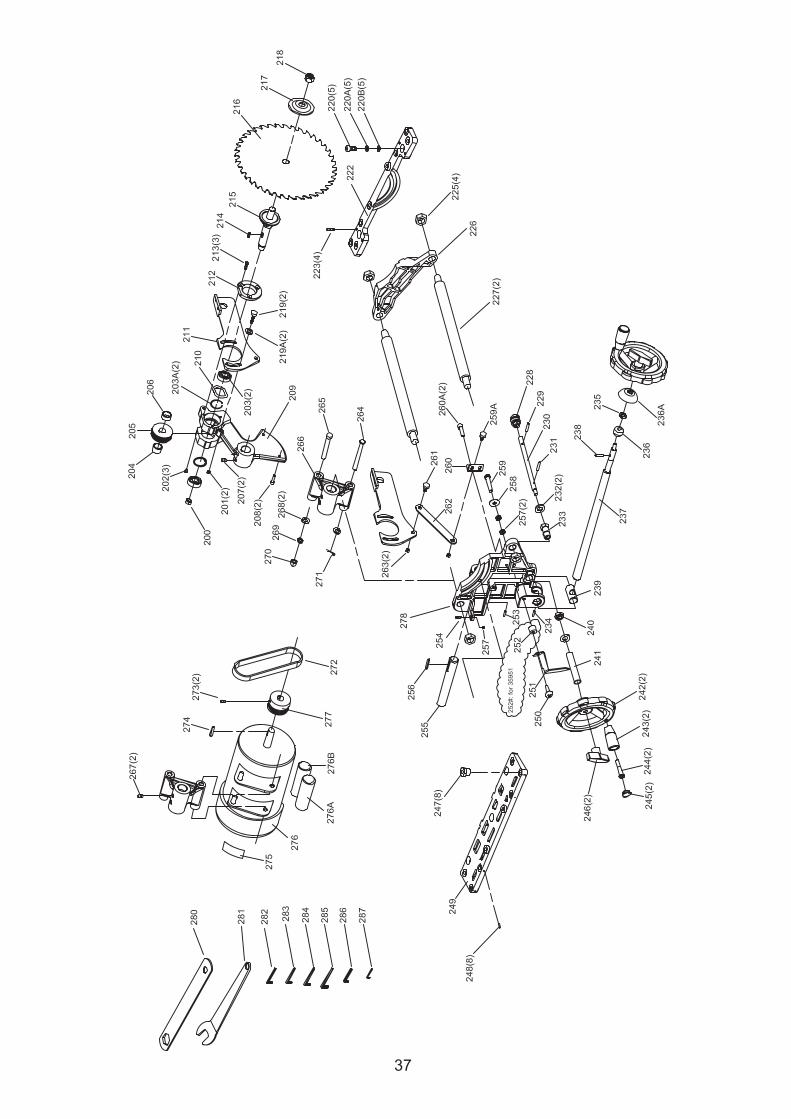
200 OR91766 LOCK NUT 5/8-18UNF 1 243 OR72942 ELEVATING KNOB ASSY 2
201 OR90235 HEX NUT M6 2 244 OR91038 KNOB BOLT 2
202 OR92137 PAN HD SCR M5x12 3 245 OR70157 KNOB END CAP 2
203 OR91733 BALL BEARING 6203 LLB 2 246 OR91046 HANDWHEEL LOCK KNOB 2
203A SC80351 CIRCLIPS FOR HOLES 40 2 247 SC10454 ADJUSTMENT SCR 8
204 SC10491 BUSHING 1 248 OR93906 HEX SOC SET SCR W/CUP POINT M5x6 8
205 SC10492 ARBOR PULLEY 1 249 SC10743 FRONT BRACKET 1
206 SC10493 BUSHING 1 250 OR90306 PAN HD SCR W/CROSS RECESS M6x12 1
207 SC80323 HEX SOC SET SCR W/CUP POINT M8x8 2 251 SC10506 POINTER 1
208 SC80104 HEX SOC HD CAP SCR M6x10 2 253 OR90308 HEX SOC SET SCR W/FLAT POINT M8x30 1
209 SC10494 ARBOR RAISING SUPPORT BRACKET 1 254 OR93891 HEX HD SCR M8x40 1
210 OR91801 WAVE WASHER 6203 1 255 SC10507 SHAFT 1
211 SC10495 SPLITTER MOUNT SUPPORT 1 256 OR74452 KEY A 6x6x35 1
212 SC10496 FLANGE PLATE 1 257 OR90307 HEX NUT M8 3
213 SC80325 HEX SOC COUNTERSUNK HD SCR M5x12 3 258 OR91084 SPECIAL WASHER (8.3x25x3.5) 1
214 OR91824 KEY 5x5x15 1 259 OR93891 HEX HD SCR M8x40 1
215 SC10497 ARBOR SHAFT 1 259A SC10508 SHOULDERED SCR 1
216 SC10721 BLADE (OD 10" , ID 5/8",TEETH :40) 1 260 SC10509 BAR SUPPORT 1
217 SC91026 BLADE FLANGE 1 260A SC80104 HEX SOC HD CAP SCR M6x10 2
218 SC10540 BLADE HEX NUT 1 261 SC10510 SHOULDERED SCR 1
219 OR73016 HEX SOC BUT HD SCR M6x35 2 262 SC10511 LINK ROD 1
219A OR90059 FLAT WASHER M6 2 263 OR91754 NYLON HEX NUT M6 2
220 OR91761 HEX SOC HD CAP SCR M8x25 5 264 SC84303 PIN 8x90 B TYPE 1
220A OR90248 LOCK WASHER M8 5 265 SC80706 HEX HD SCR M8x100 1
220B OR91084 SPECIAL WASHER (8.3x25x3.5) 5 266 SC10512 MOTOR SUPPORT BRACKET 1
222 SC10737 REAR BRACKET 1 267 SC80323 HEX SOC SET SCR W/CUP POINT M8x8 2
223 OR91821 HEX SOC SET SCR W/FLAT POINT M8x20 4 268 OR90311 FLAT WASHER M8 2
225 OR91766 LOCK NUT 5/8-18UNF 4 269 OR90248 LOCK WASHER M8 1
226 SC10499 REAR TRUNNION 1 270 OR90307 HEX NUT M8 1
227 SC10500 TIE BAR 2 271 SC84307 SPLIT PIN 3.2x22 1
228* SC10541 ELEVATING SHAFT ASSY 1 272 SC10513 BELT 170 J 1
228 OR91744 GEAR 1 273 SC80409 HEX SOC SET SCR W/CUP POINT 1/4-20×3/8" 2
229 OR91792 SPRING PIN 3x15 1 274 OR91770 KEY 5x5x36 1
230 SC10739 ELEVATING SHAFT 1 275 SC76041 MOTOR SPEC PLATE(1.5HP) 1
231 OR90232 SPRING PIN 4x20 1 276 SC72042 MOTOR ASSY 1.5 HP 1
232 OR91740 FIBER WASHER 3/8" 2 276A SC70151 START CAPACITOR 1
233 SC10501 ECCENTRIC PLUSMINUS SCR 1 276B SC72067 RUN CAPACITOR 1
234 OR93906 HEX SOC SET SCR W/CUP POINT M5x6 1 276C OR91007M CORD WFEMALE DISCONNECTION 1
235* SC10542 TILT SHAFT ASSY(#235 - #237) 1 277 OR91023 MOTOR PULLEY 1
235 SC85308 CIRCLIPS FOR SHAFT 9 1 278 SC10514 FRONT SUPPORT 1
236 SC10740 SUPPORT BUSHING 1 280 SC10515 WRENCH (7/8"x1/2") 1
237 SC10742 TILT SHAFT 1 281 SC10516 OPEN END WRENCH 22mm 1
236A SC10741 FLANGE 1 282 OR90289 ALLEN WRENCH 2.5mm 1
238 OR90232 SPRING PIN 4x20 1 283 OR90290 ALLEN WRENCH 3mm 1
239 SC10502 TILT NUT 1 284 OR90291 ALLEN WRENCH 4mm 1
240 OR91766 LOCK NUT 5/8-18UNF 1 285 OR91728 ALLEN WRENCH 5mm 1
241 SC10503 BUSHING 1 286 OR92172 ALLEN WRENCH 6mm 1
242 SC10722 HANDWHEEL 2 287 OR91808 ALLEN WRENCH 1/8" 1
39

40
KeyNo.
Part No. Description Q'ty KeyNo.
Part No. Description Q'ty
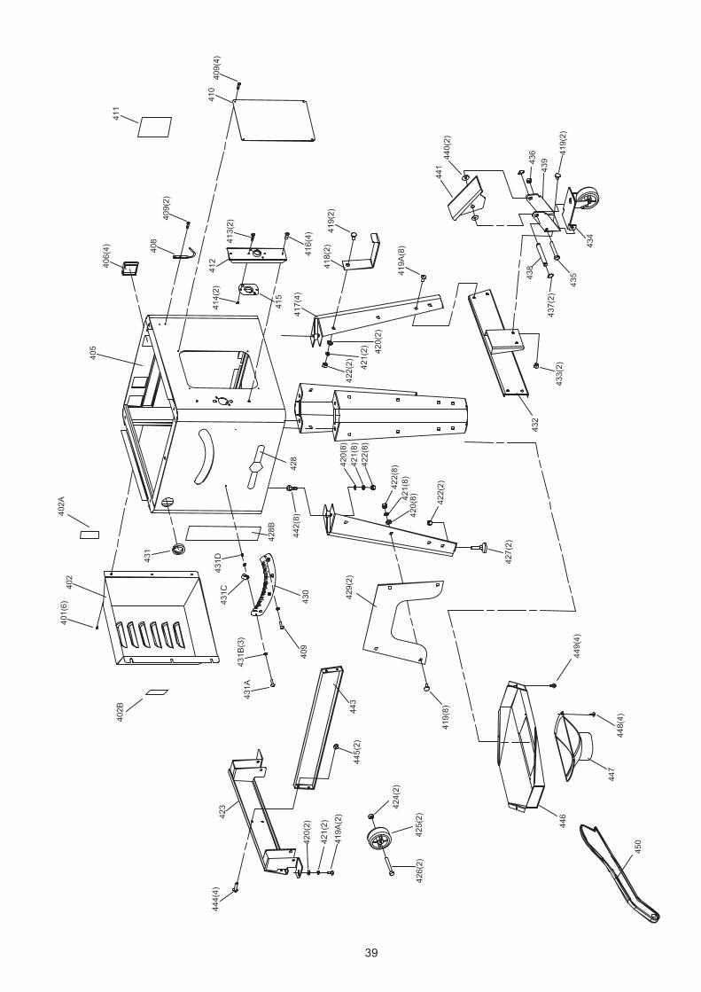
401 OR90761 PAN HD SCR W/CROSS RECESS M5x10 6 428A OR93823 RIVET ∮2x8 (Fe) 4
402 SC10520 MOTOR COVER 1 428B SC10989 BLACK RED COLOUR BAR 1
402A SC10212 WARNING LABEL (BIGGER) 1 429 SC10990 LEG SUPPORT PLATE 2
402B SC10215 WARNING LABEL (SMALLER) 1 430 SC76045 BEVEL SCALE 1
405 SC10747 CABINET ASSY WELDMENT 1 431 OR91106 INSULATOR 1
406 SC10456 END CAP 4 431A OR91775 PAN HD SCR M4x15 1
408 OR91134 WRENCH HOOK 1 431B OR90143 FLAT WASHER M4 3
409 OR91832 TRIANGULAR THREAD TAP SCR M4x8 7 431C OR91737 CABLE CLAMP 1
410 SC10523 CABINET ACCESS DOOR 1 431D OR90078 HEX NUT M4 1
411 SC10986 SPEC LABEL--45925G 1 432 SC10991 WHEEL ASSY 1
411 SC10994 SPEC LABEL--45925C 1 433 OR94771 HEX NUT FLANGED M8 2
412 SC10524 SUPPORT BOARD 1 434 OR91506 CASTER ASSY 1
413 OR90761 PAN HD SCR W/CROSS RECESS M5x10 2 435 OR91502 HEX HD SCR 5/16-18x4" 1
414 OR94428 LOCK NUT M5 2 436 OR91503 LOCK NUT 5/16-18 1
415 SC10525 FIXED BOARD 1 437 OR91507 CIRCLIPS FOR SHAFT 1/2" 2
416 OR91787 PAN HD TAP SCR 1/4-20x3/8" 4 438 OR91508 PIN 1
417 SC10987 LEG 4 439 OR72922 REAR WHEEL BRACKET 1
418 SC10527 FENCE BRACKET 2 440 OR91504 FLAT WASHER 1/2" 2
419 OR94770 CARRIAGE BOLT M8x16 12 441 OR91469 FOOT PEDAL 1
419A OR93380 HEX SOC BUT HD SCR M8x15 10 442 OR93917 HEX HD SCR M8x20 8
420 OR90311 FLAT WASHER M8 20 443 SC10992 REINFORCEMENT PLATE 1
421 OR90248 LOCK WASHER M8 20 444 SC80111 HEX SOC BUT HD SCR M6x16 4
422 OR90307 HEX NUT M8 20 445 OR90235 HEX NUT M6 2
423 SC10988 FIXED WHEEL ASSY 1 446 SC10533 DUST PLATE 1
424 OR92724 LOCK NUT M8 2 447 OR91128 DUST PORT 1
425 OR91505 CASTER WHEEL 2 448 OR91833 PAN HD TAP SCR 1/4-20x1/2" 4
426 OR94878 HEX SOC HD CAP SCR M8x55 2 449 OR92137 PAN HD SCR M5x12 4
427 SC10529 LEVELING SCREW 2 450 SC10548 PUSH STICK 1
428 OR70484 NAMEPLATE (ALUM SCTW LOGO) 1 * SC10993 MANUAL 1

NOTES
42

43


40


![[Codex] Orks 4 ed](https://static.fdocuments.in/doc/165x107/55cf85e9550346484b929b20/codex-orks-4-ed.jpg)