1. Visibility Enhancement for Silicon Debug Yu-Chin Hsu, Furshing (Kevin) Tsai, Wells Jong,...
23
1
-
Upload
cuthbert-rodgers -
Category
Documents
-
view
217 -
download
2
Transcript of 1. Visibility Enhancement for Silicon Debug Yu-Chin Hsu, Furshing (Kevin) Tsai, Wells Jong,...

1

Visibility Enhancement for Silicon Debug
Visibility Enhancement for Silicon Debug
Yu-Chin Hsu, Furshing (Kevin) Tsai, Yu-Chin Hsu, Furshing (Kevin) Tsai, Wells Jong, Ying-Tsai ChangWells Jong, Ying-Tsai Chang
3
OutlineOutline
Motivation Motivation
Design for Debug methodologyDesign for Debug methodology
Challenges in debug using silicon dataChallenges in debug using silicon data
Visibility Enhancement techniquesVisibility Enhancement techniques
Experimental resultsExperimental results
SummarySummary
4
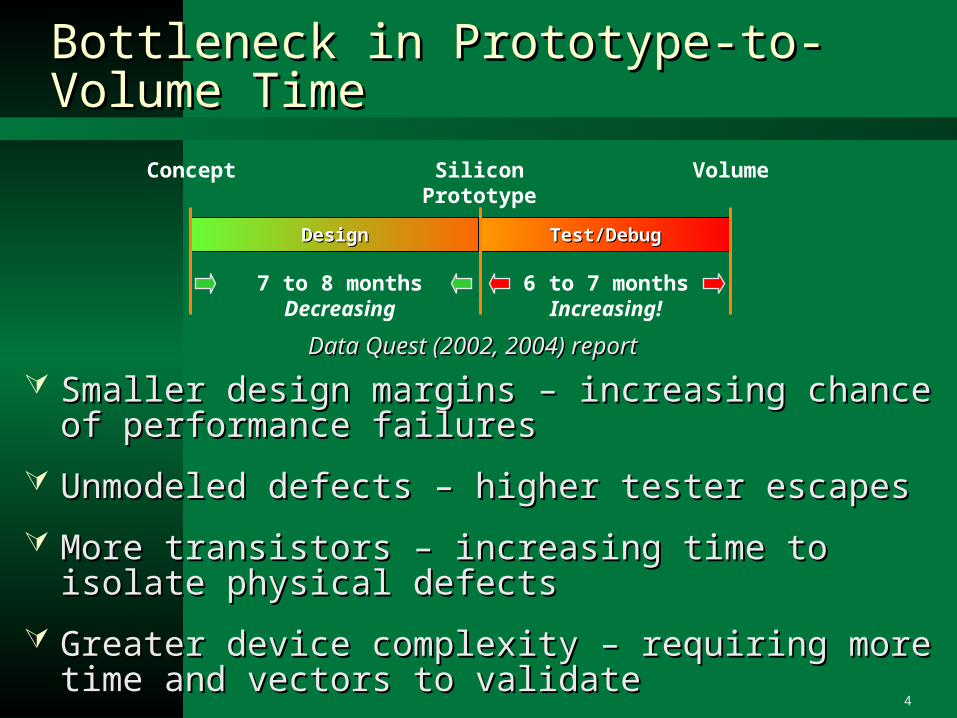
Bottleneck in Prototype-to-Volume TimeBottleneck in Prototype-to-Volume Time
Smaller design margins – increasing chance of Smaller design margins – increasing chance of performance failuresperformance failures
Unmodeled defects – higher tester escapesUnmodeled defects – higher tester escapes
More transistors – increasing time to isolate physical More transistors – increasing time to isolate physical defectsdefects
Greater device complexity – requiring more time and Greater device complexity – requiring more time and vectors to validatevectors to validate
Test/DebugTest/DebugDesignDesign
SiliconPrototype
Concept Volume
7 to 8 monthsDecreasing
6 to 7 monthsIncreasing!
Data Quest (2002, 2004) reportData Quest (2002, 2004) report
5
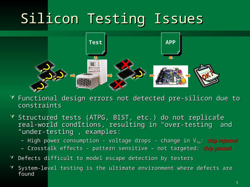
Silicon Testing IssuesSilicon Testing Issues
Functional design errors not detected pre-silicon due to Functional design errors not detected pre-silicon due to constraintsconstraints
Structured tests (ATPG, BIST, etc.) do not replicate real-world Structured tests (ATPG, BIST, etc.) do not replicate real-world conditions, resulting in “over-testing” and “under-testing”, conditions, resulting in “over-testing” and “under-testing”, examples:examples:– High power consumption - voltage drops - change in VHigh power consumption - voltage drops - change in VTHTH: : chip rejectedchip rejected– Crosstalk effects - pattern sensitive – not targeted: Crosstalk effects - pattern sensitive – not targeted: chip passedchip passed
Defects difficult to model escape detection by testersDefects difficult to model escape detection by testers
System-level testing is the ultimate environment where defects are foundSystem-level testing is the ultimate environment where defects are found
××
??????
??
?? OKOK??
TestTest APPAPP
6
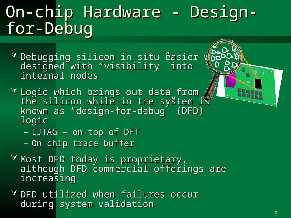
On-chip Hardware - Design-for-DebugOn-chip Hardware - Design-for-Debug
Debugging silicon in situ easier when Debugging silicon in situ easier when designed with “visibility” into designed with “visibility” into internal nodesinternal nodes
Logic which brings out data from Logic which brings out data from the silicon while in the system is known as the silicon while in the system is known as “design-for-debug” (DFD) logic“design-for-debug” (DFD) logic– IJTAG – on top of DFTIJTAG – on top of DFT– On chip trace buffer On chip trace buffer
Most DFD today is proprietary, although DFD Most DFD today is proprietary, although DFD commercial offerings are increasingcommercial offerings are increasing
DFD utilized when failures occur during DFD utilized when failures occur during system validationsystem validation

7
Design-for-Debug (DFD) on the Chip Design-for-Debug (DFD) on the Chip - Example- Example
DFDFDD is not the same as DF is not the same as DFTT::Debug logic must function Debug logic must function during system-level operationduring system-level operation
Many DFD implementations Many DFD implementations leverage DFT circuitry:leverage DFT circuitry:– IEEE 1149.1 controller IEEE 1149.1 controller
(boundary scan)(boundary scan)– Internal scan chains (full Internal scan chains (full
scan)scan)
DFD is the access DFD is the access mechanism that provides in-mechanism that provides in-situ scan register visibilitysitu scan register visibility
Scancontrol
Combinationallogic
Combinationallogic
DFTDFTDFTDFT
DFDDFD
Real-timeclock &reset
control

8
Complete System for Silicon DebugComplete System for Silicon Debug
On-chip DFD typically hooks up to a pod and is activated by a separate On-chip DFD typically hooks up to a pod and is activated by a separate software-based control programsoftware-based control program
The pod is a device that makes the electrical characteristics between The pod is a device that makes the electrical characteristics between the DFD port and the PC port compatiblethe DFD port and the PC port compatible
The DFD control program accesses data such as the internal registerThe DFD control program accesses data such as the internal register
The limited data is then processed to maximize visibility into design The limited data is then processed to maximize visibility into design operationoperation
APPAPP
podpod
scanscandatadata
scanscandatadata
VisibilityVisibilityenhancementenhancement
VisibilityVisibilityenhancementenhancement
DebugDebugDebugDebug
9
Challenges in DFD Data AnalysisChallenges in DFD Data Analysis
Limited resource available – only a subset of Limited resource available – only a subset of signals can be probedsignals can be probed
Limited visibility – only a subset of signals can Limited visibility – only a subset of signals can be extracted from siliconbe extracted from silicon
Low level of abstraction – unfamiliar design to Low level of abstraction – unfamiliar design to designerdesigner
10
Visibility Enhancement -- Visibility Enhancement -- OverviewOverview
Visibility PlanningVisibility Planning– Analyze design (RTL, gate) and provide optimal Analyze design (RTL, gate) and provide optimal
(minimal and sufficient) set of signals to be observed(minimal and sufficient) set of signals to be observed– Provide visibility tradeoff information – “expansion Provide visibility tradeoff information – “expansion
potential” of candidate signalspotential” of candidate signals
Data ExpansionData Expansion– Process limited data and expand (regenerate) missing Process limited data and expand (regenerate) missing
signal information for exploration and debugsignal information for exploration and debug– On-the-fly operation for optimal performanceOn-the-fly operation for optimal performance
Abstraction CorrelationAbstraction Correlation– Map gate-level signals and instances back to RTL Map gate-level signals and instances back to RTL
originorigin– Translate gate-level signal information (waveform Translate gate-level signal information (waveform
data) to match RTL design for designer-level debugdata) to match RTL design for designer-level debug

11
Silicon debug with Silicon debug with DFD and Visibility EnhancementDFD and Visibility Enhancement
Visibility Planning
Data Expansion &Abstraction Correlation

12
Visibility Analysis and PlanningVisibility Analysis and Planning
Visibility Analysis (VA) engine determines which Visibility Analysis (VA) engine determines which set of signals are essential for data expansionset of signals are essential for data expansion
A signal value can be made visible if its parent A signal value can be made visible if its parent (preceding gate) is visible(preceding gate) is visible
Primary inputs are considered visible Primary inputs are considered visible
13
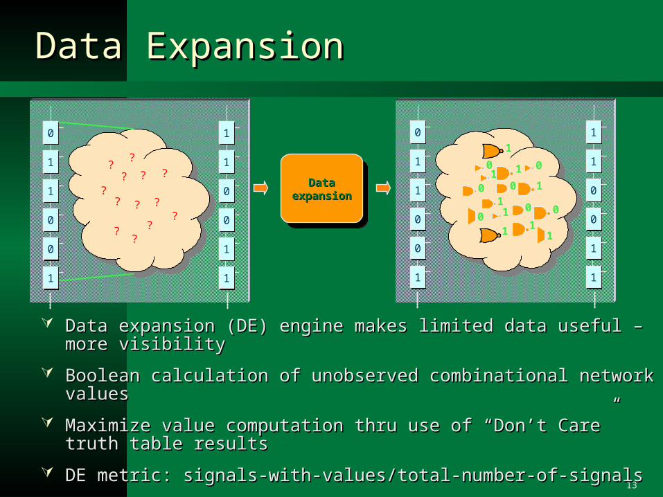
Data ExpansionData Expansion
Data expansion (DE) engine makes limited data useful – more visibilityData expansion (DE) engine makes limited data useful – more visibility
Boolean calculation of unobserved combinational network valuesBoolean calculation of unobserved combinational network values
Maximize value computation thru use of “Don’t Care” truth table resultsMaximize value computation thru use of “Don’t Care” truth table results
DE metric: signals-with-values/total-number-of-signalsDE metric: signals-with-values/total-number-of-signals
Performance optimized by expanding only the logic under investigation Performance optimized by expanding only the logic under investigation and no simulation-like timing wheel and no simulation-like timing wheel
Data Data expansionexpansion
Data Data expansionexpansion
11
00
00
11
11
00
11
11
00
00
11
11
??
? ?
?
?
?
?
?
?
?
?
?
0
1
1
1
0
00
1
0 0 1
01
11
1
11
11
00
00
11
11
11
00
00
11
11
00
14
Data Expansion - RequirementsData Expansion - Requirements
Raw signal data obtained from chip is stream of 0’s Raw signal data obtained from chip is stream of 0’s and 1’sand 1’s
Control application must make the data usable for Control application must make the data usable for analysis applicationsanalysis applications
Steps for the control application:Steps for the control application:– Assign temporal information – relative cycle time must Assign temporal information – relative cycle time must
be associated with each scan dumpbe associated with each scan dump– Map each value to an HDL signalMap each value to an HDL signal– Output the results in a usable format - VCD (IEEE Output the results in a usable format - VCD (IEEE
1364-2001) or FSDB (Novas)1364-2001) or FSDB (Novas)
15
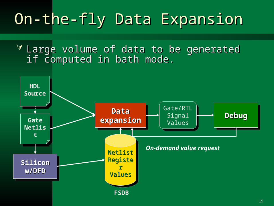
On-the-fly Data ExpansionOn-the-fly Data Expansion
HDL Source
HDL Source
Gate Netlist
Gate Netlist
SiliconSiliconw/DFDw/DFD
SiliconSiliconw/DFDw/DFD
Netlist Netlist RegisterRegisterValuesValues
Netlist Netlist RegisterRegisterValuesValues
DebugDebugDebugDebugDataDataexpansionexpansion
DataDataexpansionexpansion
Gate/RTLSignalValues
Gate/RTLSignalValues
FSDB
On-demand value request
Large volume of data to be generated if computed in Large volume of data to be generated if computed in bath mode.bath mode.
16
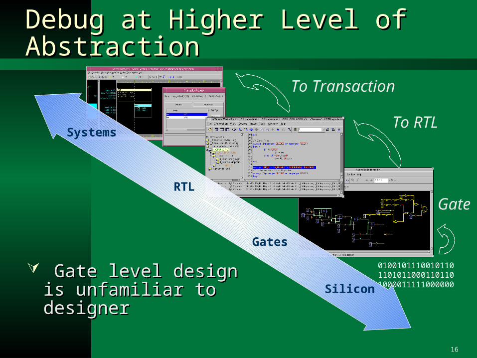
0100101110010110 11010110001101101000011111000000
Debug at Higher Level of AbstractionDebug at Higher Level of Abstraction
Gate level design is Gate level design is unfamiliar to designerunfamiliar to designer
RTL
Systems
Gates
Silicon
To RTL
To Transaction
Gate

17
Abstraction CorrelationAbstraction Correlation
Silicon signal data is usually easy Silicon signal data is usually easy to assign to gate-level signalsto assign to gate-level signals
Gate-level netlist and values are Gate-level netlist and values are difficult for RTL designers to difficult for RTL designers to understand and debugunderstand and debug
Data must be mapped to the Data must be mapped to the “designers world” for efficient “designers world” for efficient debug and collaborationdebug and collaboration
One-to-one correspondence is One-to-one correspondence is not always the case after not always the case after synthesis transformationssynthesis transformations
CorrelationCorrelationCorrelationCorrelation
18
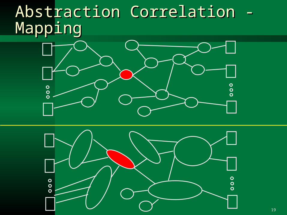
Abstraction Correlation - Mapping Abstraction Correlation - Mapping
Name-based mappingName-based mapping– Predefined rule mapping (delimiters, escaped name, naming convention for Predefined rule mapping (delimiters, escaped name, naming convention for
register, etc.)register, etc.)– Regular-expression-based user-defined renaming ruleRegular-expression-based user-defined renaming rule
Structural dependency analysisStructural dependency analysis– Find structural bounding mappable signal set of name-unmappable signal.Find structural bounding mappable signal set of name-unmappable signal.– Find structural fanin/fanout intersect of the mapped signal set for related Find structural fanin/fanout intersect of the mapped signal set for related
circuit part.circuit part.– Important concept: granularity (fundamental limitation) and relevance Important concept: granularity (fundamental limitation) and relevance
(heuristic).(heuristic).– Name-based mapping should provide a certain percentage of mapped Name-based mapping should provide a certain percentage of mapped
signals for this to work. This could often be achieved after setting some signals for this to work. This could often be achieved after setting some user-defined renaming rules because synthesis tools typically user-defined renaming rules because synthesis tools typically preserve/transform quite well some of the signal naming, especially preserve/transform quite well some of the signal naming, especially registersregisters
Other potential techniques can be functional-based correlation Other potential techniques can be functional-based correlation commonly used in equivalence checkingcommonly used in equivalence checking
19
Abstraction Correlation - Mapping Abstraction Correlation - Mapping
20
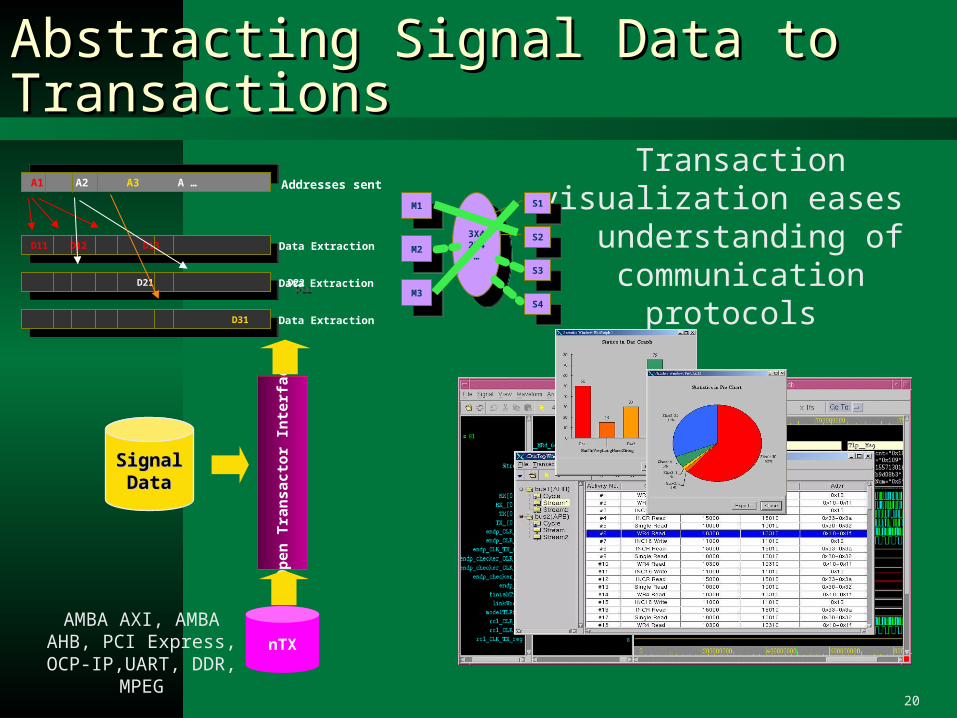
Abstracting Signal Data to TransactionsAbstracting Signal Data to Transactions
Transaction visualization eases understanding of
communication protocols
AMBA AXI, AMBA AHB, PCI Express, OCP-
IP,UART, DDR, MPEG
A1 A2 A3 A … A1 A2 A3 A … Addresses sent
D11 D12 D13 D11 D12 D13 Data Extraction
D21 D22 D21 D22 Data Extraction
D31 D31 Data Extraction
M1M1
M2M2
M3M3
3X42X4…
3X42X4…
S1S1
S2S2
S4S4
S3S3
nTX
Op
en T
ran
sact
or
Inte
rfac
e
SignalSignalDataData
21
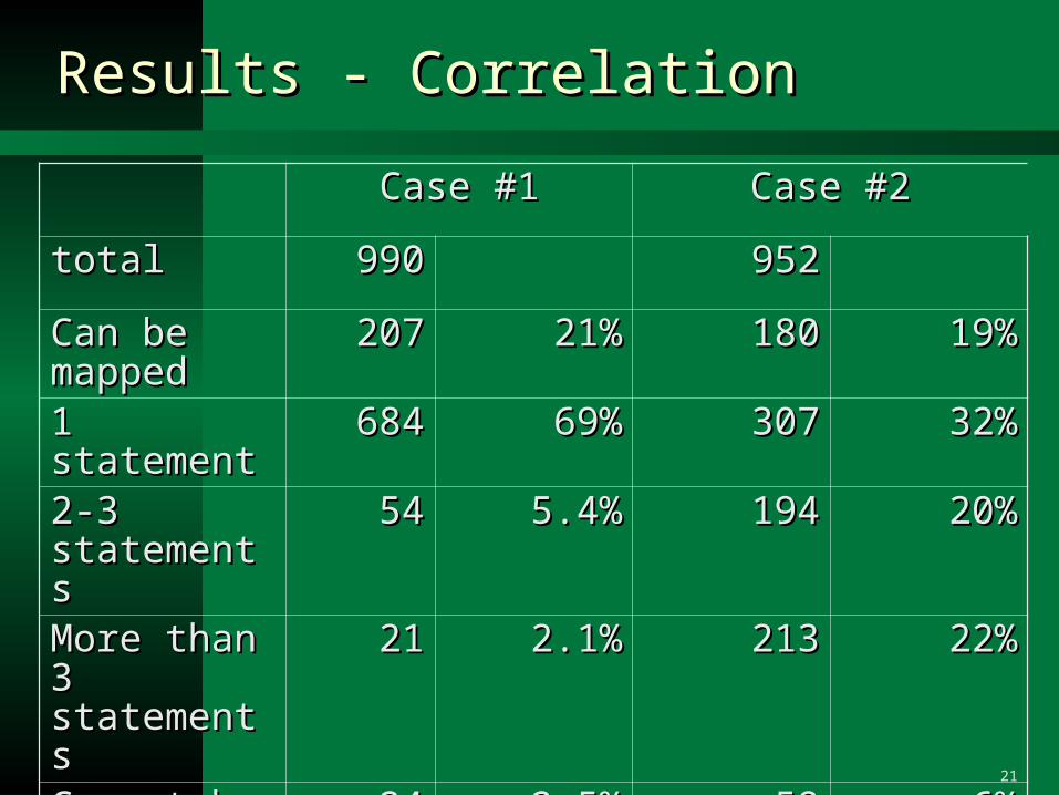
Results - CorrelationResults - Correlation
Case #1Case #1 Case #2Case #2
totaltotal 990990 952952
Can be Can be mappedmapped
207207 21%21% 180180 19%19%
1 statement1 statement 684684 69%69% 307307 32%32%
2-3 2-3 statementsstatements
5454 5.4%5.4% 194194 20%20%
More than 3 More than 3 statementsstatements
2121 2.1%2.1% 213213 22%22%
Cannot be Cannot be mappedmapped
2424 2.5%2.5% 5858 6%6%
22
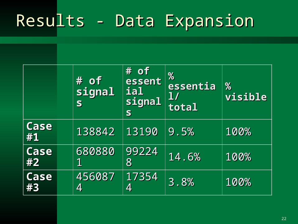
Results - Data ExpansionResults - Data Expansion
# of # of signalssignals
# of # of essential essential signalssignals
% % essential/essential/totaltotal
% visible% visible
Case #1Case #1 138842138842 1319013190 9.5%9.5% 100%100%
Case #2Case #2 68088016808801 992248992248 14.6%14.6% 100%100%
Case #3Case #3 45608744560874 173544 173544 3.8%3.8% 100%100%
23
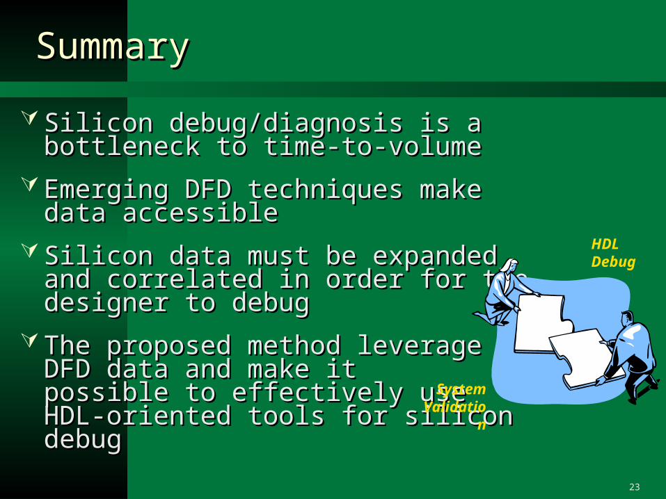
Summary Summary
Silicon debug/diagnosis is a bottleneck to Silicon debug/diagnosis is a bottleneck to time-to-volumetime-to-volume
Emerging DFD techniques make data Emerging DFD techniques make data accessibleaccessible
Silicon data must be expanded and Silicon data must be expanded and correlated in order for the correlated in order for the designer to debugdesigner to debug
The proposed method leverage The proposed method leverage DFD data and make it DFD data and make it possible to effectively use possible to effectively use HDL-oriented tools for silicon debugHDL-oriented tools for silicon debug
SystemValidation
HDLDebug