
1 © Unitec New Zealand DE4401&APTE 5601 Topic 4 N ETWORK A NALYSIS.
47
1 © Unitec New Zealand DE4401&APTE 5601 Topic 4 NETWORK ANALYSIS
-
Upload
bernadette-stevenson -
Category
Documents
-
view
215 -
download
0
Transcript of 1 © Unitec New Zealand DE4401&APTE 5601 Topic 4 N ETWORK A NALYSIS.

1© Unitec New Zealand
DE4401&APTE 5601 Topic 4
NETWORK ANALYSIS
2© Unitec New Zealand
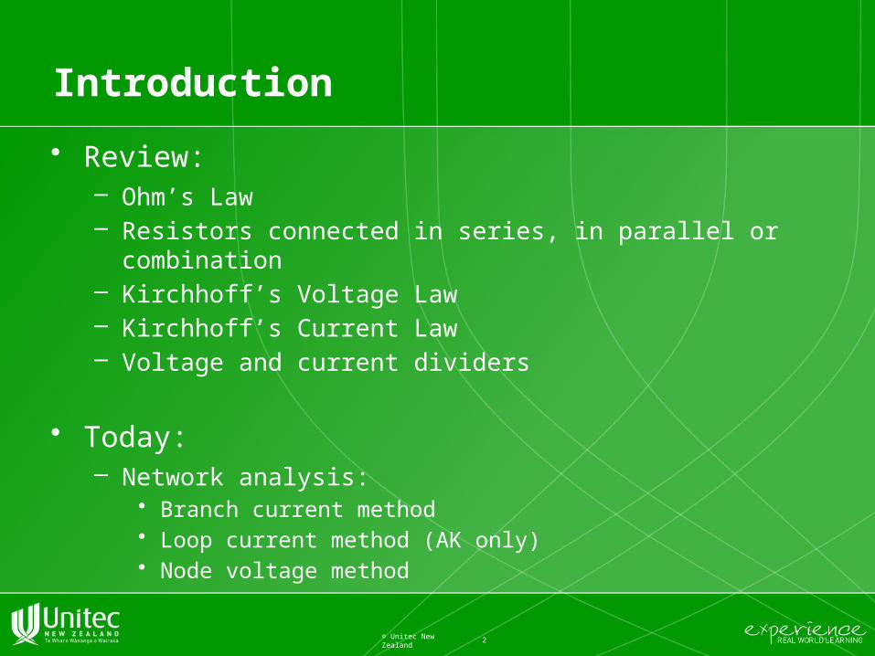
Introduction
• Review:– Ohm’s Law– Resistors connected in series, in parallel or combination– Kirchhoff’s Voltage Law – Kirchhoff’s Current Law– Voltage and current dividers
• Today:– Network analysis:
• Branch current method• Loop current method (AK only)• Node voltage method

Revision
3© Unitec New Zealand

Branch, Nodes and Loop
• KVL can be used to determine an unknown voltage in a complex circuit, where all other voltages around a particular "loop" are known.
4© Unitec New Zealand

Kirchhoff's Current Law (KCL)
• The algebraic sum of all currents entering and exiting a node must equal zero.
5© Unitec New Zealand
or

Kirchhoff's Voltage Law
• "The algebraic sum of all voltages in a loop must equal zero“
6© Unitec New Zealand

Voltage divider
7© Unitec New Zealand
• The ratio of individual resistance to total resistance is the same as the ratio of individual voltage drop to total supply voltage in a voltage divider circuit. This is known as the voltage divider formula

Current divider
8© Unitec New Zealand
It is sometimes necessary to find the individual branch currents in a parallel circuit if the resistances and total current are known, but the voltage across the resistance bank is not known. When only two branches are involved, the current in one branch will be some fraction of the total current. This fraction is the quotient of the second resistance divided by the sum of the resistances.

Network Analysis
• Generally speaking, network analysis is any structured technique used to mathematically analyze a circuit (a “network” of interconnected components).
• Usually, a single equation will not be useful and we will need a system of equations. – The rule is: we need as many equations as we have unknown
currents.
• The techniques developed for DC circuits will be used for AC circuits as well.
9© Unitec New Zealand

Network Analysis Methods
• Branch current method
• Loop current method
• Node voltage method
10© Unitec New Zealand

Branch current method
• The first and most straightforward network analysis technique is called the Branch Current Method.
• In this method, we assume directions of currents in a network, then write equations describing their relationships to each other through Kirchhoff's and Ohm's Laws.
• Once we have one equation for every unknown current, we can solve the simultaneous equations and determine all currents, and therefore all voltage drops in the network.
11© Unitec New Zealand

Branch current method steps
Steps to follow for the “Branch Current” method of analysis:
(1) Choose a node and assume directions of currents.
(2) Write a KCL equation relating currents at the node.
(3) Label resistor voltage drop polarities based on assumed currents.
(4) Write KVL equations for each loop of the circuit, substituting the product IR for E in each resistor term of the equations.
(5) Solve for unknown branch currents (simultaneous equations).– If any solution is negative, then the assumed direction of current for that
solution actually flows the opposite way!
(6) Solve for voltage drops across all resistors (E=IR).
12© Unitec New Zealand

Example 1
13© Unitec New Zealand

(1) Choose a node and assume directions of currents.
14© Unitec New Zealand
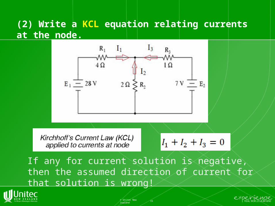
(2) Write a KCL equation relating currents at the node.
15© Unitec New Zealand
If any for current solution is negative, then the assumed direction of current for that solution is wrong!

(3) Label resistor voltage drop polarities based on assumed currents.
• The following is not the case in our example here, but just so you know: It is OK if the polarity of a resistor's voltage drop doesn't match with the polarity of the nearest battery, so long as the resistor voltage polarity is correctly based on the assumed direction of current through it. In some cases we may discover that current will be forced backwards through a battery, causing this very effect.
16© Unitec New Zealand

(4) Write KVL equations for each loop of the circuit, substituting the product IR for E in each resistor term of the equations.
17© Unitec New Zealand
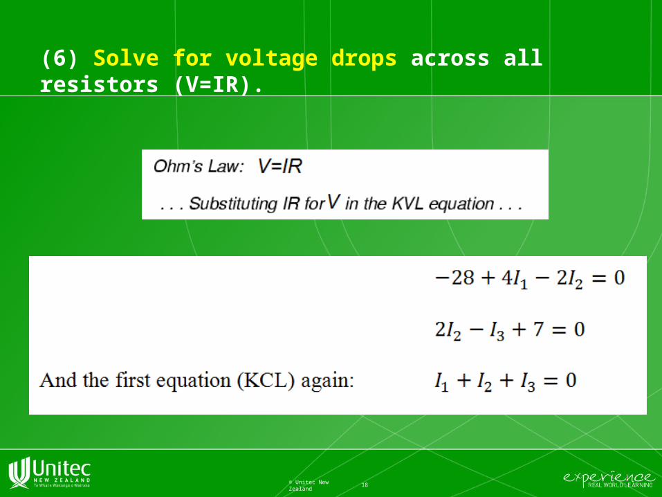
(6) Solve for voltage drops across all resistors (V=IR).
18© Unitec New Zealand

(5) Solve for unknown branch currents (simultaneous equations).
• If any solution is negative, then the assumed direction of current for that solution is wrong!
19© Unitec New Zealand

Loop (Mesh) Current Method
• The Loop Current Method, also known as the Mesh Current Method, is quite similar to the Branch Current method in that it uses simultaneous equations, Kirchhoff's Voltage Law, and Ohm's Law to determine unknown currents in a network.
• It differs from the Branch Current method in that it does not use Kirchhoff's Current Law.
20© Unitec New Zealand
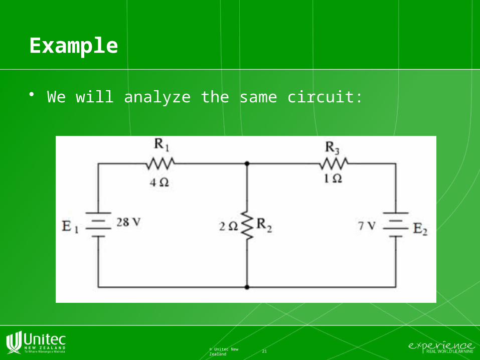
Example
• We will analyze the same circuit:
21© Unitec New Zealand

Step one: identify “loops”• Identify “loops” within the circuit, encompassing all
components. – In our example circuit:
• First loop is formed by E1, R1, and R2
• Second loop is formed by E2, R2, and R3
– The choice of each current's direction is arbitrary, but the equations are easier to solve if the currents are going the same direction through intersecting components (here, R2 ).
22© Unitec New Zealand

Step two: label all voltage drop polarities
• The next step is to label all voltage drop polarities across resistors according to the assumed directions of the loop currents. – The battery polarities, of course, are dictated by their symbol
orientations in the diagram, and may or may not “agree” with the resistor polarities (assumed current directions)
23© Unitec New Zealand
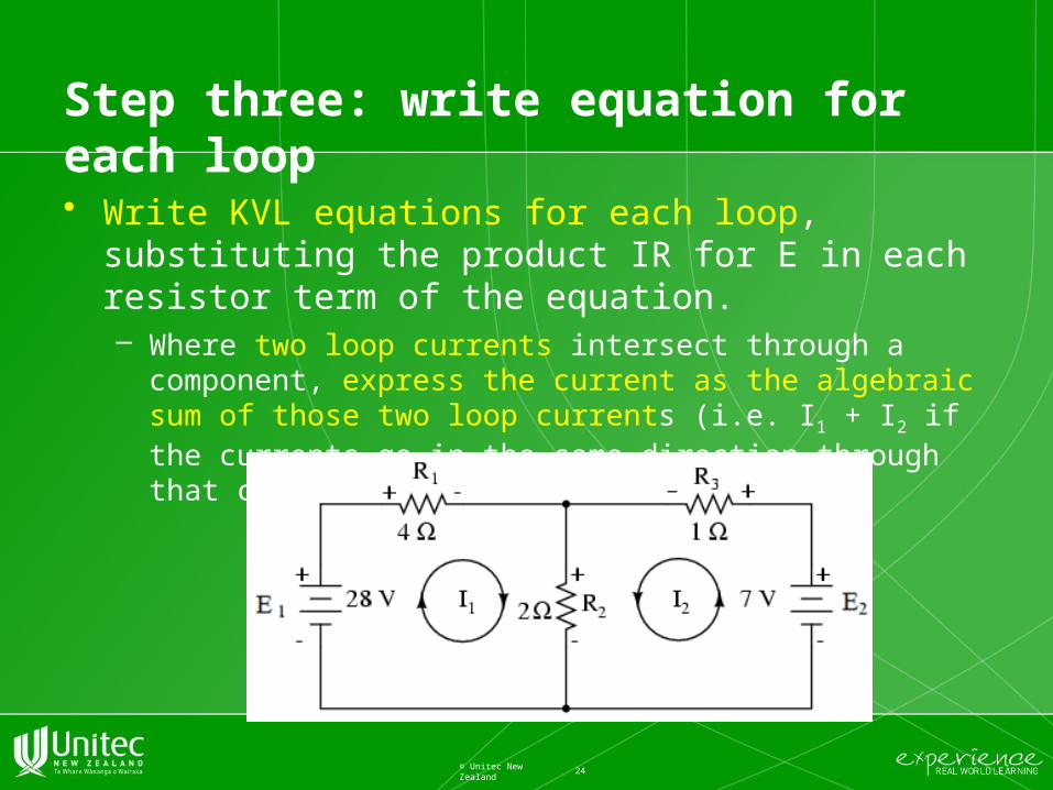
Step three: write equation for each loop
• Write KVL equations for each loop, substituting the product IR for E in each resistor term of the equation. – Where two loop currents intersect through a component,
express the current as the algebraic sum of those two loop currents (i.e. I1 + I2 if the currents go in the same direction through that component or I 1 - I2 if not.)
24© Unitec New Zealand

Step four: solve the equations
• In this example we have two equations with two unknowns
25© Unitec New Zealand

Step five: calculating branch currents
• The result we have obtained is for the loop currents, not branch currents. So, in this step, we must go back to our diagram to see how they fit together to give currents through all components (branch currents).– Remember: negative current value means that the current flows
in the direction opposite from the assumed. (see figure below)
26© Unitec New Zealand
This change of current direction from what was first assumed will alter the polarity of the voltage drops across R2 and R3 due to current I2.

Step five (cont.)
• We can say that the current through R1 is 5 amps. Also, we can safely say that the current through R3 is 1 amp, with a voltage drop of 1 volt (E=IR), positive on the left and negative on the right.
• To determine the actual current through R2, we must see how mesh currents I1 and I2 interact
• in this case they're in opposition
27© Unitec New Zealand
We algebraically add them (minding the sign +/-) : Since I1 is going “down” at 5 amps, and I2 is going “up” at 1 amp, the real current through R2 must be the difference, 4 amps, going “down”
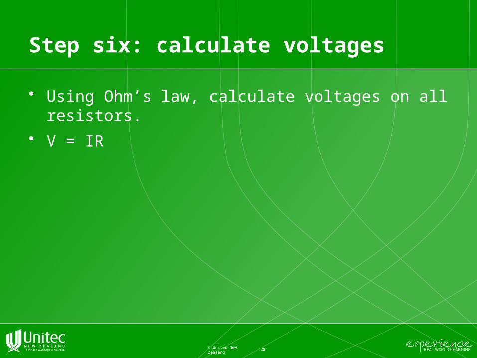
Step six: calculate voltages
• Using Ohm’s law, calculate voltages on all resistors.
• V = IR
28© Unitec New Zealand

Loop current method: advantages
• The primary advantage of Loop Current analysis is that it generally allows for the solution of a large network with fewer unknown values and fewer simultaneous equations than Branch Current method. – Our example problem took three equations to solve the Branch
Current method and only two equations using the Loop Current method.
29© Unitec New Zealand

Revise Steps for Loop Current Method
(1) Draw currents in loops of circuit, to account for all components.
(2) Label resistor voltage drop polarities based on assumed directions of loop currents.
(3) Write KVL equations for each loop, substituting the product IR for E in each resistor term of the equation. Where two mesh currents intersect through a component, express the current as the algebraic sum of those two mesh currents (i.e. I1 + I2 if the currents go in the same direction through that component or I 1 - I2 if not.)
(4) Solve for unknown loop currents (simultaneous equations). If any solution is negative, the assumed current direction is wrong!
(5) Algebraically add loop currents to find current in components which share multiple loop currents.
(6) Solve for voltage drops across all resistors (V=IR).
30© Unitec New Zealand
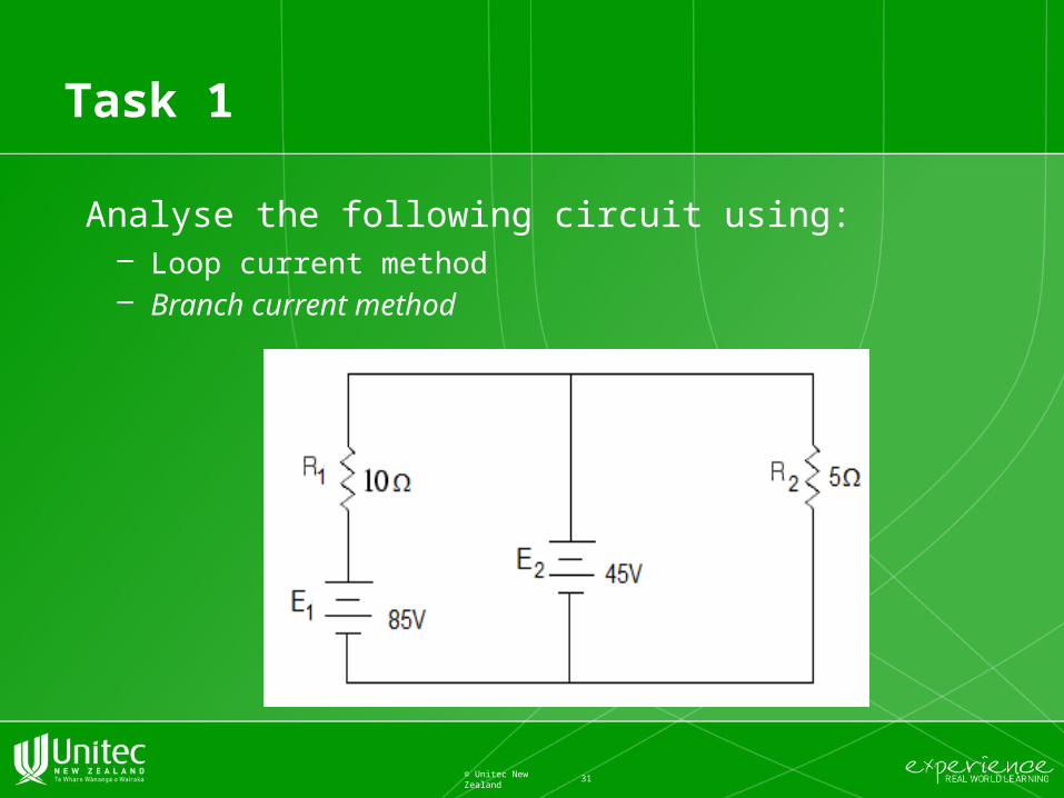
Task 1
Analyse the following circuit using:– Loop current method– Branch current method
31© Unitec New Zealand

Task 2
• Analyse the following circuit using:– Loop current method– Branch current method
32© Unitec New Zealand

Node Voltage Method
• Node Voltage Method is one of the major techniques in circuit analysis. It reduces the number of equations you have to deal with.
• Node Voltage Method for solving a circuit uses node voltage drops to specify the currents at a node. Then, node equations of currents are written to satisfy Kirchhoff's current law. By solving the node equations, we can calculate the unknown node voltages.
33© Unitec New Zealand

Terminology
• A node is a common connection for two or more components in a circuit.
• A principal node has three or more connections (some call it ‘junction’)
• One of the principal nodes is chosen as a reference node and this node is connected to the ground (defined as 0 volts).– Because a reference node has 0 volts, you can simplify analysis
by choosing a node where a large number of devices are connected as your reference node.
• A node voltage is the voltage of a given node with respect to the reference node (i.e.to the ground).
34© Unitec New Zealand
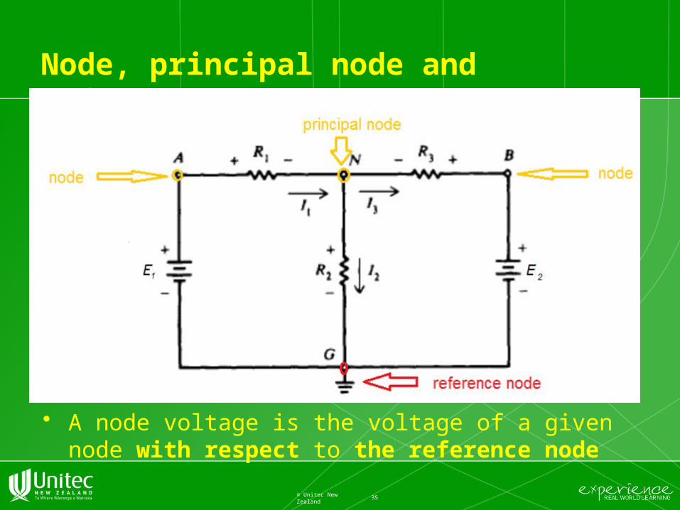
Node, principal node and reference node
• A node voltage is the voltage of a given node with respect to the reference node
35© Unitec New Zealand

Notation used in this class
• To each node in a circuit, a letter or number is assigned. Example: A, B, G, and N are nodes, and G and N are principal nodes.
• Select node G connected to ground as the reference node. – Then VAG is the voltage between nodes A and G, VBG is the
voltage between nodes B and G, and VNG is the voltage between nodes N and G.
– Since the node voltage is always determined with respect to a specified reference node, the notations VA for VAG, VB for VBG, and VN for VNG are used.
•
36© Unitec New Zealand

Steps for Node Voltage Method
1. Mark nodes (use letters i. e. A, B, C, G). Select a reference (ground) node.
2. Assume the direction of currents. Mark the voltage polarity across each resistor, consistent with assumed direction of current.
3. Formulate a Kirchhoff’s Current Law (KCL) equation for each non-reference principal node.
4. Express all branch currents in terms of voltage drops on components (e.g. resistor in the branch) by using relationships such as Ohm’s law ( I = V/R) and the rule for the voltage in parallel branches (“ all parallel branches have the same voltage”). Resulting equations are now expressed in terms of unknown principal voltages.
5. With the equations from step 4, go back to the KLC equations from step 3. Simplify the equations to put them in standard form.
6. Solve the system of equations to find principal node voltages.
7. Next, find all voltage drops and currents in the branches.
37© Unitec New Zealand

Example: we analyse the same circuit
• Step one: Mark nodes and select a reference (ground) node.
38© Unitec New Zealand
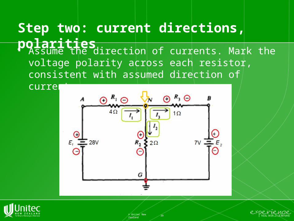
Step two: current directions, polarities
• Assume the direction of currents. Mark the voltage polarity across each resistor, consistent with assumed direction of current.
39© Unitec New Zealand

Step three: KCL
• Formulate a Kirchhoff’s Current Law (KCL) equation for each non-reference principal node.– In this case, only one principal node, N.
40© Unitec New Zealand

Step four: Voltage equations
• Express all branch currents in terms of voltage drops on components (e.g. resistor in the branch) by using relationships such as Ohm’s law ( I = V/R) and the rule for the voltage in parallel branches (“ all parallel branches have the same voltage”). Resulting equations are now expressed in terms of unknown principal voltages.
41© Unitec New Zealand
Step five and step six:
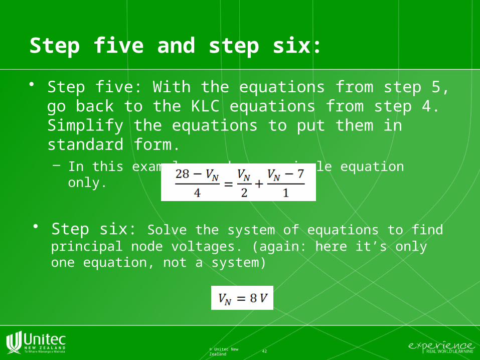
• Step five: With the equations from step 5, go back to the KLC equations from step 4. Simplify the equations to put them in standard form.– In this example, we have a single equation only.
42© Unitec New Zealand
• Step six: Solve the system of equations to find principal node voltages. (again: here it’s only one equation, not a system)

Step seven
• Next, find all voltage drops and currents in the branches.
43© Unitec New Zealand
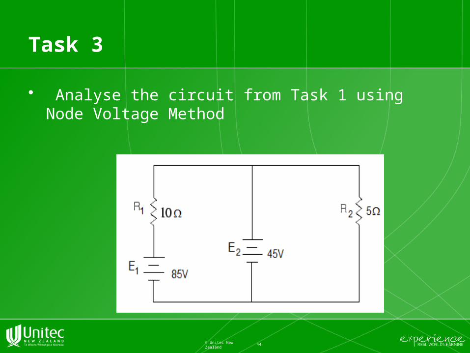
Task 3
• Analyse the circuit from Task 1 using Node Voltage Method
44© Unitec New Zealand

Task 4
• Analyse the circuit from Task 2 using Node Voltage Method
45© Unitec New Zealand
Literature for Node Voltage Method
• Chapter 5 in book: ‘Circuit Analysis For Dummies’Santiago, John; available online from Unitec Library
• Page 105 Schaum’s Basic Electricity ; available from Moodle in pdf format for download or a book from Unitec Library
46© Unitec New Zealand
Maths revision
• If algebra is a problem for you, please look up “system of equations” in Khan academy.– In the class, we will use Elimination method. – Please practice Substitution and Matrix methods as well.
47© Unitec New Zealand


![5601 Traveller - [S13] Veterans](https://static.fdocuments.in/doc/165x107/577c81151a28abe054ab6884/5601-traveller-s13-veterans.jpg)

