1. The Large Hadron Collider 2. The General Purpose ...wsmith/cms/GIFvirdee1_new.pdf · Machine...
71
GIF – Annecy 2001 1 Search for the Higgs at the LHC 1. The Large Hadron Collider 2. The General Purpose Detectors 3. Tools and Algorithms 4. Search for the SM Higgs 5. Search for the Supersymmetric Higgs’’ 6. Conclusions Tejinder S. Virdee CERN/Imperial College
Transcript of 1. The Large Hadron Collider 2. The General Purpose ...wsmith/cms/GIFvirdee1_new.pdf · Machine...

GIF – Annecy 2001 1
Search for the Higgs at the LHC
1. The Large Hadron Collider2. The General Purpose Detectors3. Tools and Algorithms4. Search for the SM Higgs5. Search for the Supersymmetric Higgs’’6. Conclusions
Tejinder S. VirdeeCERN/Imperial College

GIF – Annecy 2001 2
1. The Large Hadron Collider
i. The Machine Parametersii. Machine Scheduleiii. Experimental Challenge

GIF – Annecy 2001 3
Energy Frontier
New Energy DomainSearch for the unexpectedCover domain ~ 1 TeV in which SM without the Higgs (or equivalent) gives nonsense
Exploratory machine required� hadron-hadron collider with:Largest possible primary energyLargest possible luminosity

GIF – Annecy 2001 4
Energy and Luminosity
Hadron colliders are broad-band exploratory machinesMay need to study WL-WL scattering at a cm energy of ~ 1 TeV
� EW ~ 500 GeV� Equark ~ 1 TeV� Eproton ~ 6 TeV
� pp collisions at 7 + 7 TeV
Event Rate = L.σ.BRe.g. H(1 TeV) � ZZ � 2e+2µ or 4e or 4µFor L ~1034 , Evts/yr = 1034 10-37.10-3.107 ~ 10 /yr !!
p pq
q
Z0
Z0
H
WW

GIF – Annecy 2001 5
CERN Site

GIF – Annecy 2001 6
CERN Accelerator Complex

GIF – Annecy 2001 1
LHC Layout and Parameters
Magnetic Fieldp (TeV) = 0.3 B(T) R(km)For p= 7 TeV, R= 4.3 km� B = 8.4 T
Energy at collision E 7 TeVDipole field at 7 TeV B 8.33 TLuminosity L 1034 cm-²s-¹Beam beam parameter ξ 3.6 10-3
DC beam current Ibeam 0.56 ABunch separation 24.95 nsNo. of bunches kb 2835No. particles per bunch Np 1.1 1011
Normalized transverse εn 3.75 µmemittance (r.m.s.)
Collisionsβ-value at IP β* 0.5 mr.m.s. beam radius at IP σ* 16 µmTotal crossing angle φ 300 µradLuminosity lifetime τL 10 hNumber of evts/crossing nc 17Energy loss per turn 7 keVTotal radiated power/beam 3.8 kWStored energy per beam 350 MJ
FNkf
Ln
pb
*
2
4 βπεγ
=
f revolution frequencykb no. of bunchesNp no. of protons/bunchεn norm transverse emittanceβ* betatron functionF reduction factor xing angle
n
pNr
πεξ
4=Beam-beam tune shift

GIF – Annecy 2001 8
LHC Beam Structure
Detailed beam structure is determined by injection scheme and properties of the dump system. Bunches are formed in the 26 GeV PS with the correct 25ns spacing. Beam is subsequently accelerated to 450 GeV and transferred to the LHC. This operation is repeated 12 times for each counter-rotating beam. At each transfer, enough space has to be reserved to accommodate rise time of injection kickersFinally a longer gap of 3.17 µs is reserved for rise time of dump kicker by eliminating 1 PS batch

GIF – Annecy 2001 9
Dipole Magnets
1232 superconducting dipoles

GIF – Annecy 2001 10
Dipole Magnets
Dipole/quadrupole Interconnect
Alsthom LHC Dipole No. 1

GIF – Annecy 2001 11
Pre-series Dipole Magnets
Training Quenches at 1.8K - first runs
6.00
6.25
6.50
6.75
7.00
7.25
7.50
7.75
8.00
8.25
8.50
8.75
9.00
9.25
9.50
9.75
10.00
Quench Number
Mag
neti
c F
ield
at
Que
nch
B [
Tes
la]
Ultimate Field = 9T Nominal Field = 8.34 Tesla
No Quench
Training Quench
Provoked Quench
HCMBB-A000102000001
HCMBB-A000101000002
HCMBB-A000101000001
HCMBB-A000103000001

GIF – Annecy 2001 12
String 2
■ String 2: under construction
◆ Full LHC cell
● 6 dipoles + 4 quads
◆ Last tests before commissioning
◆ String 2 has the same layout as a LHC cell in the regular part of an arc and follows the curvature of the tunnel. The first half-cell starts with a Short Straight Section (SSS), which is connected to the cryogenic line and is followed by three 15-m dipoles. Following the simplified cryogenic scheme, the second half-cell is not connected to the cryogenic line.

GIF – Annecy 2001 13
Civil Engineering

GIF – Annecy 2001 14
Civil Engineering: Progress
CMS Underground HallReady in mid-04
ATLAS Underground HallReady in mid-03
GIF – Annecy 2001 15
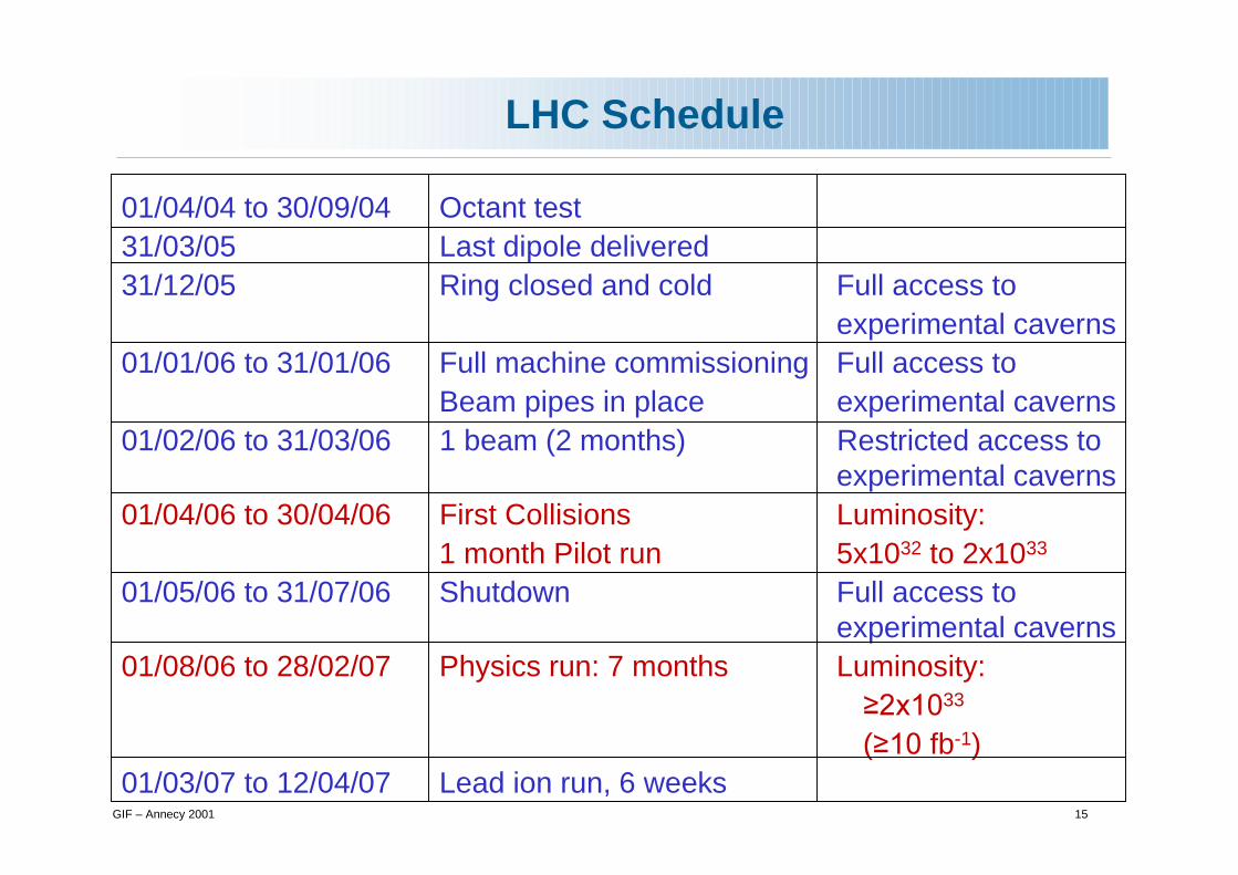
LHC Schedule
01/04/04 to 30/09/04 Octant test31/03/05 Last dipole delivered31/12/05 Ring closed and cold Full access to
experimental caverns01/01/06 to 31/01/06 Full machine commissioning Full access to
Beam pipes in place experimental caverns01/02/06 to 31/03/06 1 beam (2 months) Restricted access to
experimental caverns01/04/06 to 30/04/06 First Collisions Luminosity:
1 month Pilot run 5x1032 to 2x1033
01/05/06 to 31/07/06 Shutdown Full access to experimental caverns
01/08/06 to 28/02/07 Physics run: 7 months Luminosity: �����33
(����fb-1)01/03/07 to 12/04/07 Lead ion run, 6 weeks

GIF – Annecy 2001 16
LHC Schedule
-04 Apr-04 Jul-04 Oct-04 Jan-05 Apr-05 Jul-05 Oct-05 Jan-06 Apr-06 Jul-06 Oct-06 Jan-07 Apr-07 Jul-07 Oct-07
Octant test
01/04 to
31/08
Last dipoledelivered
31/03
Ring closedand cold
31/12
First beam
01/02
Physics run
7 months
L>2x10 33
01/08 28/02
Pilot run01/04 to 30/04
Shutdown3 months
2004
2005
2006
2007
Pb-Pb run6 weeks

GIF – Annecy 2001 17
Experimental Challenge
High Interaction Rate
pp interaction rate 109 interactions/sdata for only ~100 out of the 40 million crossings can be recorded per secLevel-1 trigger decision will take ~2-3 ms� electronics need to store data locally (pipelining)
Large Particle Multiplicity
~ <20> superposed events in each crossing~ 1000 tracks stream into the detector every 25 nsneed highly granular detectors with good time resolution for low occupancy� large number of channels
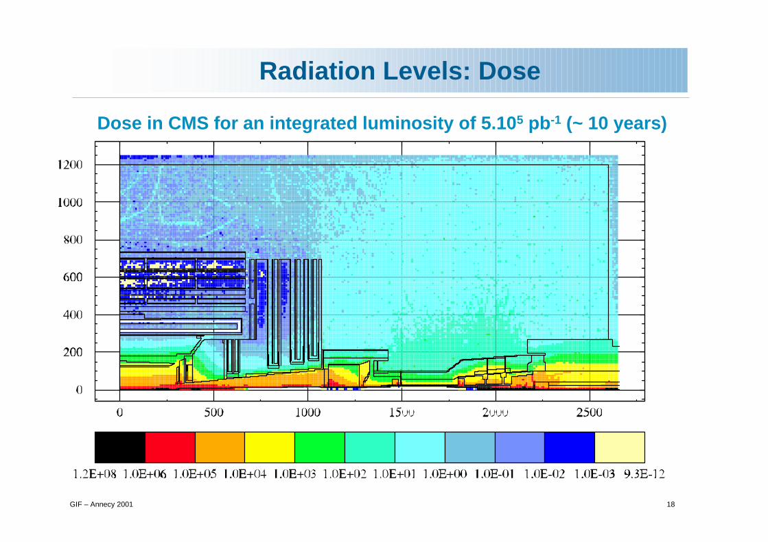
High Radiation Levels
� radiation hard (tolerant) detectors and electronics
GIF – Annecy 2001 18
Radiation Levels: Dose
Dose in CMS for an integrated luminosity of 5.105 pb-1 (~ 10 years)

GIF – Annecy 2001 19
Radiation Levels: Neutron Fluence
n fluence in CMS for an integrated luminosity of 5.105 pb-1 (~ 10 years)

GIF – Annecy 2001 20
2. The General Purpose Detectors
i. Physics Requirementsii. GPDs: ATLAS and CMSiii. Physics Performance of GPDs

GIF – Annecy 2001 21
Physics Requirements I
Natural Width - 0.01 1 10 100 GeV
At the LHC the SM Higgs provides a good benchmark to test the performance of a detector
LEP

GIF – Annecy 2001 22
Physics Requirements II
Very good muon identification and momentum measurementtrigger efficiently and measure sign of a few TeV muons
High energy resolution electromagnetic calorimertry~ 0.5% @ ET~50 GeV
Powerful inner tracking systemsfactor 10 better momentum resolution than at LEP
Hermetic calorimetrygood missing ET resolution
(Affordable detector)

GIF – Annecy 2001 23
Designs of General Purpose Detectors
CMSMeasurement of p in tracker and B return flux; Solenoid with Fe flux returnProperty: muon tracks point back to vertex
ATLASStandalone p measurement; safe for high multiplicities;Air-core toroid Property: σp flat with η
Complementary Conception
solenoid

CMS
CSS00
Onion-like Structure of HEP Experiments
Each layer identifies and measures (or remeasures) the energy of particles
unmeasured by the previous layer
Charged trackse±,µ±,h±
e±,γ
hadrons (h)
Muons ( µ)
Lightweight materials
High Z materials eg. lead tungstate crystals
Heavy materialseg. Iron or Copper + active mediaHeavy Absorber
e.g. Fe
tracker
e.m. calo
hadron calo.
Zone in which only ν and µ remain
µ detectors
No single detector can determine identity and measure
energies/momenta of all particles

CMS
CSS00
Transverse View of CMS

GIF – Annecy 2001 24
The ATLAS Detector

GIF – Annecy 2001 25
CMS
GIF – Annecy 2001 26
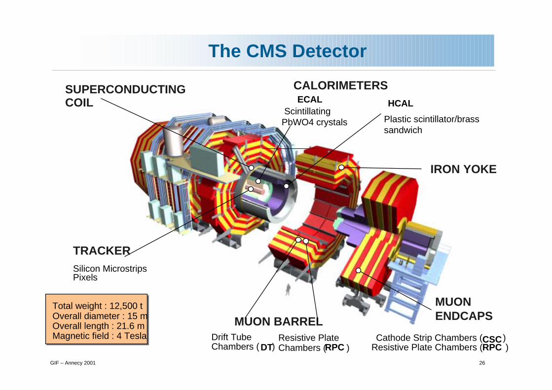
The CMS Detector
MUON BARREL
CALORIMETERS
Silicon MicrostripsPixels
ECALScintillating
PbWO4 crystals
Cathode Strip Chambers ( )CSCResistive Plate Chambers ( )RPC
Drift TubeChambers ( )DT
Resistive PlateChambers ( )RPC
SUPERCONDUCTINGCOIL
IRON YOKE
TRACKER
MUONENDCAPS
Total weight : 12,500 tOverall diameter : 15 mOverall length : 21.6 mMagnetic field : 4 Tesla
HCAL
Plastic scintillator/brasssandwich

GIF – Annecy 2001 27
Choice of the Magnets
● Ampere’s thm: 2πRB=µ0nI→ nI=2x10⁷ At
● With 8 coils, 2x2x30 turns: I=20kA (superC)● Challenges: mechanics, 1.5GJ if quench, spatial & alignment precision over large surface area
● B=µ0nI; @2168 turns/m→I=20kA (SuperC)● Challenges: 4-layer winding to carry enough I, design of reinforced superC cable
CMS: B=4T (E=2.7 GJ!)
Design goal: measure 1 TeV muons with 10% resolution
ATLAS: <B>~0.6T over 4.5 m → s=0.5mm → need σs=50µm

GIF – Annecy 2001 28
Magnet Construction
Completed ATLAS solenoid and cryogenics chimney during tests at
Toshiba (for KEK)
CMS barrel yoke wheels assembled at SX5 (point 5)
Central wheel supports the coil, barrel HCAL, ECAL and tracker
GIF – Annecy 2001 29
Tracking at LHC
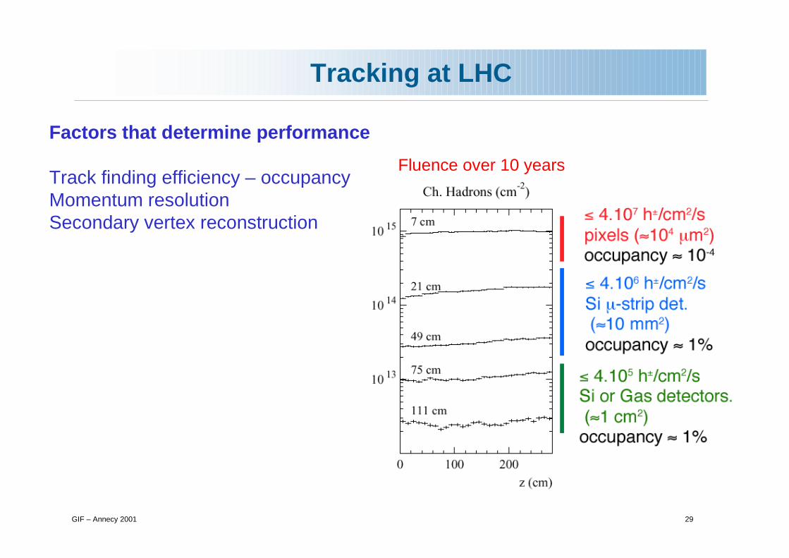
Factors that determine performance
Track finding efficiency – occupancyMomentum resolutionSecondary vertex reconstruction
Fluence over 10 years

GIF – Annecy 2001 30
Trackers at LHC
ATLAS
1.2m
3.5m
CMS: Si pixels surrounded by silicon strip detectorsPixels: ~ 1 m2 of silicon sensors, 40 M pixels, 150x150 µm2 , r = 4, 7, 11 cmSi µ-strips : 223 m2 of silicon sensors, 10 M strips, 12 pts, r = 20 – 120 cm
Pixels: ~ 2.3 m2 of silicon sensors, 140 M pixels, 50x300 µm2, r = 4, 10, 13 cmSi µ-strips : 60 m2 of silicon sensors, 6 M strips, 4 pts, r = 30 - 50 cmStraws TRT: 36 straws/track, Xe-CO2-CF4 φ=4mm, r = 56 - 107 cm

GIF – Annecy 2001 31
Front-end Electronics
digitaloptical link
Optical transmitter
AAAAAA
AA
AAAAAAAAAAAA
ADC
RAMTTCrx
TTCrx µPFront End Driver
T1
Front End Controller
I2C
Front End ModuleDetector
Control module
PLL
CLK
CCUAAAAAAAAA
AAAAAAAAAA
AA
AAAA
analogueoptical link
DCU
Tx/Rx
Tx/Rx
APV
APVMUX
256:1
FPGA
FPGA
���������������
�������������
��������������������
���������������
����
������������������ ���
�!"
�#�#
���$�%&'
(���������������)!#

GIF – Annecy 2001 32
Electromagnetic Calorimetry at LHC
In several scenarios moderate mass narrow states decaying into photons or electrons are expected:
SM : intermediate mass H � γγ, H � Z Z* � 4eMSSM: h � γγ, H � γγ, H � Z Z* � 4e
In all cases the observed width will be determined by the instrumental mass resolution. Need :
good e.m. energy resolutiongood photon angular resolutiongood two-shower separation capability

GIF – Annecy 2001 33
Hadronic Calorimetry at LHC

GIF – Annecy 2001 34
CMS Calorimeters
ECAL: PbWO4 crystals
HCALCentral Region (|η|<3) : Brass/Scintillator with WLS fibre readout, projective geometry, granularity ∆ηx∆φ = 0.0875x0.0875Forward Region (3<|η|<5): Fe/Quatz Fibre, Cerenkov light

GIF – Annecy 2001 35
ATLAS Calorimeters
ECALAccordion Pb/LAr|η|<3.2, 3 samplingsS1: ∆ηx∆φ = 0.025x0.1S2: ∆ηx∆φ = 0.025x0.025S3: ∆ηx∆φ = 0.05x0.025
HCALBarrel: Fe/Scintillator with WLS fibre readout3 samplings - ∆ηx∆φ = 0.1x0.1Endcap: Fe/LArForward: W/LAr3.1<|η|<4.9∆ηx∆φ = 0.2x0.2
EM Barrel calorimeter with EM Barrel calorimeter with presamplerpresampler
Forward calorimeterForward calorimeter
EM EndEM End--Cap calorimeter Cap calorimeter with with presamplerpresampler
HadronicHadronic EndEnd--Cap Cap calorimetercalorimeter
1.475
4.9
2.5

GIF – Annecy 2001 36
The Calorimeters
HEC 1module
20

GIF – Annecy 2001 37
Muons
Muon identification should be easy at L ~ 1034 cm-2 s-1
Muons can be identified inside jetsb-tagging, control efficiency of isolation cuts
Factors that determine performance
Level-1 Triggerrate from genuine muons (b,c � µX) is very high � must make a pT cut with
v. high efficiency – flexible threshold (pT in the range 5 – 75 GeV)
Pattern Recognitionhits can be spoilt by correlated backgrounds (δs, em showers, punchthrough)
and uncorrelated ones (ns and associated photons)
Momentum Resolutionhigh momenta involved � high B.dlgood chamber resolution (~ 100 µm) and good alignmentfor low momenta precision comes from inner tracking

GIF – Annecy 2001 38
ATLAS Muon Detectors
MDTMDT
TGC
RPC
CSC
Monitored Drift Tubes (| | < 2) with a single wire resolution of 80 m1194 chambers, 5500m2
Cathode Strip Chambers (2 < | | < 2.7)at higher particle fluxes32 chambers, 27 m2
Each detector has 3 stations.Each station consists of 2-4 layers.
Resistive Plate Chambers (| | < 1.05)with a good time resolution of 1 ns1136 chambers, 3650 m2
Thin Gap Chambers (1.05 < | | < 2.4)at higher particle fluxes1584 chambers, 2900 m2
Precision chambers Trigger chambers

GIF – Annecy 2001 39
CMS Muon Detectors

GIF – Annecy 2001 40
Muon Chambers
CMS Drift Tubes
ATLAS TGC
ATLAS MDT
CMS CSC
GIF – Annecy 2001 41
3. Tools and Algorithms
i. Minimum Bias Eventsii. Isolation Criteriaiii. Muon/electron/gamma reconstructioniv. Jet reconstruction and Missing ETv. b/t taggingvi. Triggering

GIF – Annecy 2001 1
Production Cross-sectons
At sqrt(s)=14 TeVσtot ~ 105 mbσελαστιχ ~ 28 mbσsingle diffractive ~ 12 mbσdouble diffractive ~ mbσinel ~ 60 mb
Evt rate = L.σ = 1034 x 60 10-27 /s= 6x10⁸ /s
Not all bunches are full (2835/3564)� events/crossing ~ 20
Operating ConditionsFor every ‘good’ event containing a Higgs decaythere are ~ 20 extra ‘bad’ minimum bias interactions superposed

GIF – Annecy 2001 43
Characteristics of MB Events: Tracks

GIF – Annecy 2001 44
Event Pileup
20 min bias evts overlap
H→ZZ (Z →µµ)

GIF – Annecy 2001 45
Characteristics of MB Events: Energy
CMS: Transverse energy flow in ∆ηx∆φ ~ 0.1x0.1 at L=1034 cm -2s-1
η=0.1 η=2.2

GIF – Annecy 2001 46
Isolation Criteria
Isolation is one of the most powerful tools at Hadron Colliders – leptons and photons from sub-processes are isolated
∆R= sqrt(∆φ2 + ∆η2)
�∆R
e.g. γ isolation using charged tracks (CMS) – energy deposits can also be used
γ
area used to measure energy
area used for isolation
Rejection power against π0s in jets
Loss of efficiency at Hi L for H�γγ

GIF – Annecy 2001 47
Material in Trackers
ATLASCMS

GIF – Annecy 2001 48
Charged Track Reconstruction
Muons
Pions
ATLASPattern
Recognition>9 precision hits
+ 2 pixel hits+ σd < 1mm

GIF – Annecy 2001 49
Electron Reconstruction
Reconstruction of electrons that radiate little (and unconverted γs) is simple : eg. CMS -collect energy in an array of 5 x 5 crystals centred on ~ impact point
For ‘bremming’ e’s and converting γ’s, challenge is in coping with the combined result of tracker material and the 4T magnetic field (CMS) – problem is not energy loss but spraying/spreading of energy
ETe=35 GeV CMS Barrel

GIF – Annecy 2001 50
Gamma Reconstruction
CMS BarrelHiggs � γγ�� ~ 90%
Unconverted �s Converted �s
5x5 5x9 anddynamic
¼ of conversions cannot be reconstructed
Conversions

GIF – Annecy 2001 51
Jet Reconstruction
Classical ‘cone’ algorithm - jet built around a seed• parameters: ET
seed cut, cone opening radius ∆RATLAS
∆R=0.4pileup+el noise *
el noise o
W + jetsET
jet > 20 GeV
ATLAS: W � jet-jet mass resolution
pTW(GeV) ∆R σLoL σHiL (GeV)
pT<50 0.4 9.5 13.8 100<pT<200 0.4 7.7 12.9200<pT<700 0.3 5.0 6.9
100<pTW<200 200<pT
W<700
����������

GIF – Annecy 2001 52
Missing ET
A � ττ mA=150 geV

GIF – Annecy 2001 53
�-Jet Rejection
ATLAS EM calorimeter4 mm η-strips in first compartment
3 longitudinal segments
� (γ−jet + jet-jet) < 40% γγ
Detailed MC
Cuts (ATLAS)ETγ1,ETγ2 > 40, 25 GeV with |η| < 2.5EH1/Eem
Eem23x3/ Eem2
7x7
Shower width in ηTrack Veto
εγ ~ 80% all L

CMS
CSS00
γ / π0 Separation
Isolated π0's - detect presence of 2 em showers.
CMS Barrel • use fine transverse crystal granularity (2.2×2.2 cm2)• Compare energy deposited by single γ and π0 in 3×3 crystal array variables - 9-energies, x and y position, and a pair measuring the shower width
CMS Endcap • use preshower - two planes of Si strips with fine pitch (≈2mm) compare signal (summed in 1,2 or 3 adjacent strips with the total signal in 21 adjacent strips centred on strip with highest signal
BarrelEndcap

GIF – Annecy 2001 54
b-jets
Likelihood methodForm significance Si for i-th trk in jetForm ri=fb(Si)/fu(Si)Form Jet weight W = Slog ri

GIF – Annecy 2001 55
�-jets
�-identification – variablesRem – jet radius using em cells∆ET
12 – ETem/Et
had within 0.1<∆R<0.2Ntr – no. charged trks pT> 1,2,5 GeV
within ∆R=0.3
High pT
Medium
Low
ATLAS �-jets QCD jets
�-jet separationA��� QCD b-jets tt
pT(τ) 73 44 58 65Rem < 0.07 45% 1.1% 1.9% 1.3%∆ET
12 < 0.1 32% 0.6% 0.9% 0.7%Ntr(pT>2):1or 3 25% 0.2% 0.2% 0.2%

GIF – Annecy 2001 56
��� mass reconstruction
Invariant mass of ττ pair can be reconstructed assuming mτ=0 and νs go in the direction of τ-jets
u1 and u2 are directions of jetspx
miss, pymiss components of
ETmiss vector
Solve equation if sin∆φ ne 0 i.e. ττ system must be boosted ( ττ are not back to back) Mass resolution ~ 10%
Jets system
τ1 � � + νs
ETmiss
τ2 � h (+π0s)+ νs

GIF – Annecy 2001 57
Forward Jet Tagging
Tag Jet Fake Jet
Tagging Jets

GIF – Annecy 2001 58
Level-1 Isolated Electron Trigger
Fine-grain: ��������������������������ETmin
Isolated
“e/γ”
ET( ) + max ET( ) > ETmin
φη
�7
�� �������� ������������
���
����������������������� ����
�������
�������
�������
����� ���
��������� �������������� ����
ET( ) / ET( ) < HoEmax
At least 1 ET( , , , ) < Eisomax

GIF – Annecy 2001 59
Level-1 Muon Trigger
Pt = 3.5, 4.0, 4.5, 6.0 GeV
Trigger based on tracks in external muon detectors that point to interaction region
• Low-pT muon tracks don’t point to vertex
- Multiple scattering - Magnetic deflection • Two detector layers - Coincidence in “road”
Detectors: RPC (pattern recognition) DT(track segment)

GIF – Annecy 2001 60
Level-1 Muon Trigger

GIF – Annecy 2001 61
Level-1 Trigger Rates
Physics efficiencies

GIF – Annecy 2001 62
Trigger Architectures
- 30 Collisions/25ns ( 10 9 event/sec ) 107 channels (10 16 bit/sec)
Multilevel trigger and readout systems
Luminosity = 1034 cm-2 sec-1 25 ns
25ns
40 MHz
105 Hz
103 Hz
102 Hz
Trigger Rate
Lvl-1
Lvl-2
Lvl-3
Front end pipelines
Readout buffers
Processor farms
Switching network
Detectors
µsec
ms
sec
25ns
40 MHz
105 Hz
102 Hz
Trigger Rate
Lvl-1
HLT
Front end pipelines
Readout buffers
Processor farms
Switching network
Detectors
µsec
sec
ATLASCMS

GIF – Annecy 2001 63
Data Acquisition
16 Million channels
100 kHzLEVEL-1 TRIGGER
1 Megabyte EVENT DATA
200 Gigabyte BUFFERS500 Readout memories
3 Gigacell buffers
500 Gigabit/s
Gigabit/s SERVICE LAN Petabyte ARCHIVE
Energy Tracks
Networks
1 Terabit/s(50000 DATA CHANNELS)
5 TeraIPS
EVENT BUILDER.A large switchingnetwork (512+512 ports) with a total throughput ofapproximately 500 Gbit/s forms the interconnectionbetween the sources (Readout Dual Port Memory)and the destinations (switch to Farm Interface). TheEvent Manager collects the status and request ofevent filters and distributes event building commands(read/clear) to RDPMs
EVENT FILTER. It consists of a set of highperformance commercial processors organized into manyfarms convenient for on-line and off-line applications.The farm architecture is such that a single CPUprocesses one event
40 MHzCOLLISION RATE
Charge Time Pattern
Detectors
Computing services

GIF – Annecy 2001 64
Higher Level Trigger
■ Example: inclusive electron trigger from Lvl-1
◆ Step 1: fetch calo (& muon data)
● Apply Lvl-1 verification; sharper threshold
● Apply π0 rejection (based on crystals only)
● Apply isolation but skip if pixel info can be used immediately
◆ Accept (say) 10-20% of the events
● Draw road inside tracker (this road would contain all hits from the electron track if this is indeed an electron)
● Fetch all tracker modules that have geometrical boundaries inside the road
◆ Find charged particle track
● From CDF: track gives factor ~50; but factor 5 above, so this is factor 10 now. If event passes, read in rest of the tracker

GIF – Annecy 2001 65
HLT – Electron Trigger
80
50

GIF – Annecy 2001 66
Physics Selection at LHC
LEVEL-1 Trigger Hardwired processors (ASIC, FPGA) Pipelined massive parallel
HIGH LEVEL Triggers Farms of
processors
10-9 10-6 10-3 10-0 103
25ns 3µs hour yearms
Reconstruction&ANALYSIS TIER0/1/2
Centers
ON-line OFF-line
sec
Giga Tera Petabit

GIF – Annecy 2001 67
Physics Studies : Simulation
• Trigger evt generated at bx=0, Pile-Up generated from bx=-5 to bx=+3;• Pulse shape computed every 25ns(time-samples) for each hit;• Signal processing:Add samples if several hits insame cell; Pile-Up treated like Trigger evt, i.e. add samples;
• Energy extracted from 3 pedestal + 5 signal samples(ECAL)
• Weights chosen for optimal energy resolution;
• Timing and goodness-of-fit also available
-5 -4 -3 -2 -1 0 1 2 3 4 5 6 7 8 9 10 11 12 13 14 15 16 17 18 19 20
t (25ns units)
pu
lse
shap
e
-5 -4 -3 -2 -1 0 1 2 3 4 5 6 7 8 9 10 11 12 13 14 15 16 17
t (25ns units)
pu
lse
shap
e
• Gaussian, uncorrelated noise injected in each time-sample
������������ ������
From an in-time pulse to observable at 1034cm-2s-1

GIF – Annecy 2001 68
Physics Performance
Muon Momentum Resolution
Spatial resolution Š 100 µm/station
Momentum Resolution
∆pt/p
t - 0.15p
t 0.5% (p
t in TeV)
SOLENOID B = 4 Tesla, R=3m
Radius of tracking cavity = 1.3 m PbWO4 CRYSTAL ELECTROMAGNETIC
CALORIMETER
Track Finding Efficiency
isolated µ tracks 98% isolated h± tracks 92% trks in 300 GeV b-jets 90%
pt > 2 GeV, |η| < 2.5
b - tagging
50% efficiency for a rejection factor of 100 against u, d and s jets
δpt/p
t - 10%
at pt=500 GeV at η=2
Energy reconstructed in 3 x 3 crystals
σ / E - 2.7% / ¦ E ⊕ 0.5% ⊕ 20%/E (E in GeV)
High Granularity Tracker