1 Testing Numerical Transformer Differential Relays 2011
50
Texas A&M Protective Relaying Conference 2011 Testing Numerical Transformer Differential Relays Steve Turner Beckwith Electric Co., Inc.
-
Upload
adeel-zafar -
Category
Documents
-
view
96 -
download
20
description
testing differential relay
Transcript of 1 Testing Numerical Transformer Differential Relays 2011
Texas A&M Protective Relaying Conference 2011
Testing Numerical Transformer Differential Relays
Steve Turner
Beckwith Electric Co., Inc.
Texas A&M Protective Relaying Conference 2011
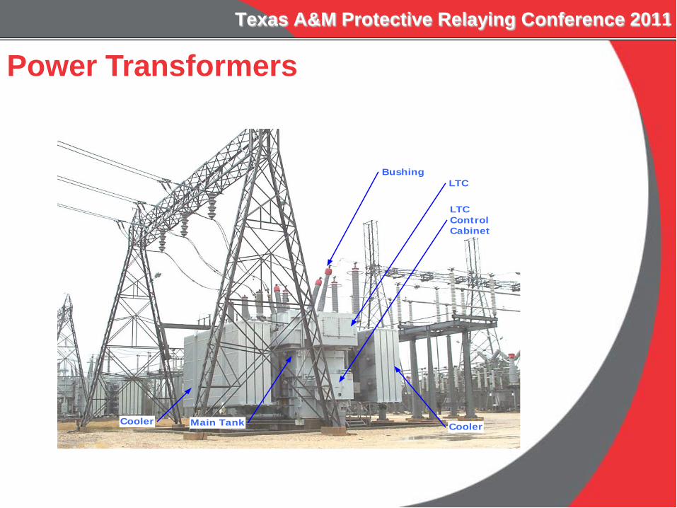
Bushing
Cooler
LTC
LTCControlCabinet
Cooler Main Tank
Power Transformers

Testing Numerical Transformer Differential Relays
Commissioning versus Maintenance Testing
Main Transformer Protection: Restrained Phase Differential High Set Phase Differential Ground Differential
INTRODUCTION

Testing Numerical Transformer Differential Relays
Topics: Transformer Differential Boundary Test
(Commissioning) Ground Differential Sensitivity Test
(Commissioning/Maintenance) Secondary Transformer Protection Harmonic Restraint for Transformer Inrush
(Maintenance)
INTRODUCTION
Testing Numerical Transformer Differential Relays
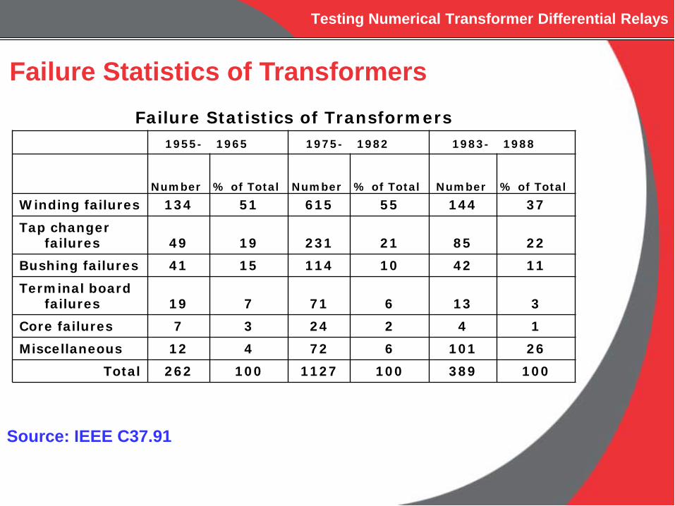
Failure Statistics of Transformers 1955- 1965 1975- 1982 1983- 1988
Number % of Total Number % of Total Number % of TotalWinding failures 134 51 615 55 144 37
Tap changer failures 49 19 231 21 85 22
Bushing failures 41 15 114 10 42 11
Terminal board failures 19 7 71 6 13 3
Core failures 7 3 24 2 4 1Miscellaneous 12 4 72 6 101 26
Total 262 100 1127 100 389 100
Source: IEEE C37.91
Failure Statistics of Transformers
Testing Numerical Transformer Differential Relays
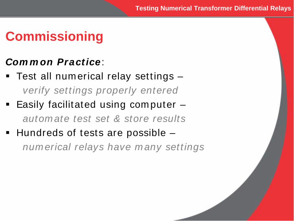
Commissioning
Common Practice: Test all numerical relay settings –
verify settings properly entered Easily facilitated using computer –
automate test set & store results Hundreds of tests are possible –
numerical relays have many settings
Testing Numerical Transformer Differential Relays
Commissioning
Final Goal Ensure the transformer is properly protected for the
particular application
Testing Numerical Transformer Differential Relays
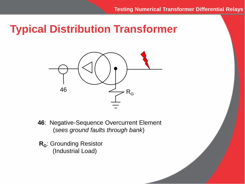
RG46
Typical Distribution Transformer
46: Negative-Sequence Overcurrent Element(sees ground faults through bank)
RG: Grounding Resistor(Industrial Load)
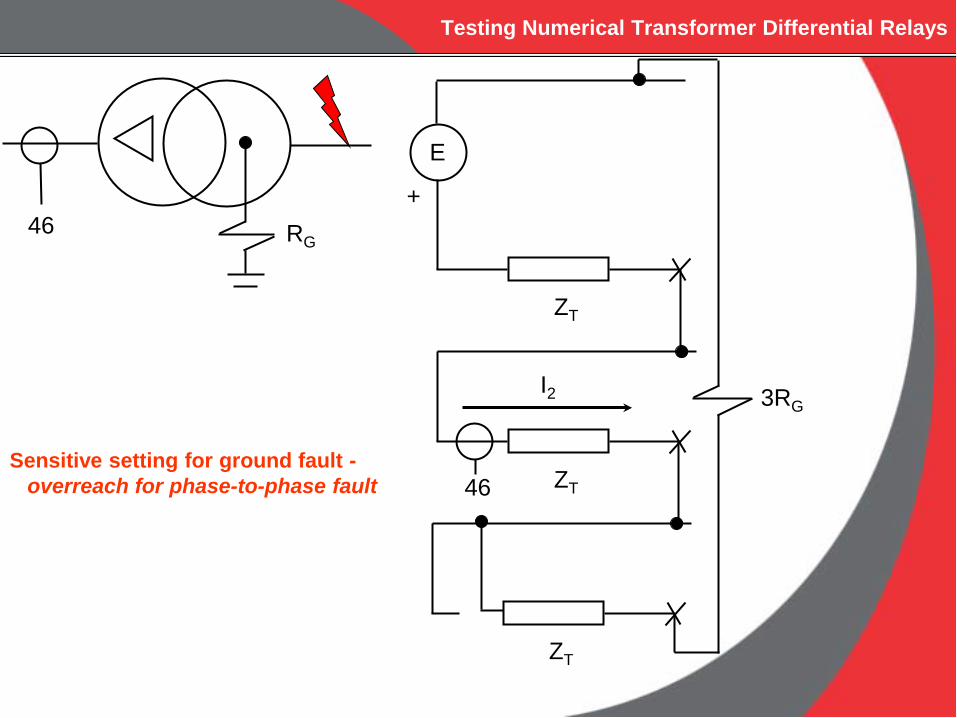
Testing Numerical Transformer Differential Relays
RG46
E
+
ZT
ZT
ZT
3RG
46
I2
Sensitive setting for ground fault -overreach for phase-to-phase fault

Testing Numerical Transformer Differential Relays
Transformer Differential CharacteristicBoundary Test
I2I1
87
Y YYY
I1 = Winding 1 per unit current (A, B or C-phase)
I2 = Winding 2 per unit current (A, B or C-phase)
3 elements per function (A, B & C-phase)
* Simulate Through Current

Testing Numerical Transformer Differential Relays
Differential CharacteristicOperating Equations
Id = |I1 – I2|, Differential Current
Ir = |I1| + |I2|, Restraint Current2

Testing Numerical Transformer Differential Relays
Differential Characteristic
Id
Ir
MinimumPickup(per unit)
XY
% = YX
*100%

Testing Numerical Transformer Differential Relays
Differential Characteristic
Id
Ir
MinimumPickup

Testing Numerical Transformer Differential Relays
Matrix
IdIr[ ] =
1 -1½ ½ [ ] * I1
I2[ ]

Testing Numerical Transformer Differential Relays
Inverted Matrix
I1I2[ ] =
½ 1-½ 1 [ ] * Id
Ir[ ]
Testing Numerical Transformer Differential Relays
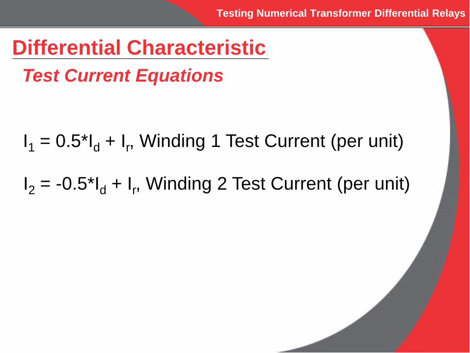
Differential CharacteristicTest Current Equations
I1 = 0.5*Id + Ir, Winding 1 Test Current (per unit)
I2 = -0.5*Id + Ir, Winding 2 Test Current (per unit)

Testing Numerical Transformer Differential Relays
Differential CharacteristicTest Points
Id
Ir
MinimumPickup
Minimum Pickup = 0.2 per unit
Slope = 28.6%
1 23
4
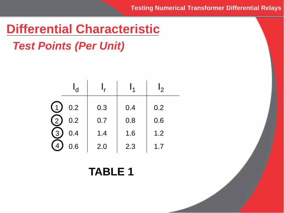
Testing Numerical Transformer Differential Relays
Differential CharacteristicTest Points (Per Unit)
Id Ir I1 I2
1 0.2 0.3 0.4 0.2
0.2 0.7 0.8 0.6
0.4 1.4 1.6 1.2
0.6 2.0 2.3 1.7
2
3
4
TABLE 1

Testing Numerical Transformer Differential Relays
Delta-Wye Differential Characteristic
I2I1
87
YYY
I1 = Winding 1 per unit current (A, B or C-phase)
I2 = Winding 2 per unit current (A, B or C-phase)
3 elements per relay (A, B & C-phase)
* Simulate Through Current
DAB

Testing Numerical Transformer Differential Relays
Delta-Wye Differential Characteristic(Relay Internally Compensates Test Currents)
IA1relay = IA1/TAP1
DAB WINDING
IB1relay = IB1/TAP1
IC1relay = IB1/TAP1
IA2relay = (IA2- IB2)/(TAP2*SQRT(3))
WYE WINDING
IB2relay = (IB2 - IC2)/(TAP2*SQRT(3))
IC2relay = (IC2 - IA2)/(TAP2*SQRT(3))
TAP# = MVA#
kV#LL*CTR#*SQRT(3)

Testing Numerical Transformer Differential Relays
Delta-Wye Differential Characteristic(Single-Phase Test for A-Phase Element)
Id Ir I1 I2
0.2 0.7 0.8 0.62
From TABLE 1:
IA1 = I1*TAP1IA2 = I2*TAP2*SQRT(3)
IA1test = 0.8*TAP1
IA2test = 0.6*TAP2*SQRT(3)

Testing Numerical Transformer Differential Relays
ABCABC II
=
100010001
' ABCABC II
−−
−=
101110
011
31'
A
C B
C
B
A
A
C
BB
C A
C
B A
A
B C
B
A C
C
A B
B
A
C
C
B
A
A
C
B
ABCABC II
−−
−=
001100
010'
ABCABC II
=
010001100
'
ABCABC II
−−
−=
100010001
'
ABCABC II
=
001100010
'
ABCABC II
−−
−=
010001100
'
ABCABC II
−−
−=
011101
110
31'
ABCABC II
−−
−=
110011101
31'
ABCABC II
−−
−=
101110011
31'
ABCABC II
−−
−=
011101110
31'
1:0O
3:60O
5:120O
7:180O
9:240O
11:300O
B
A
C
ABCABC II
−−
−=
110011101
31'
2:30O
4:90O
6:150O
8:210O
10:270O
12:330O
y g
As an example, if we have a two winding transformer with Y/Delta-AC connection (or YD1)with Y-Y cts. This will be equivalent to case 2 with a 30o phase shift.
Testing Numerical Transformer Differential Relays
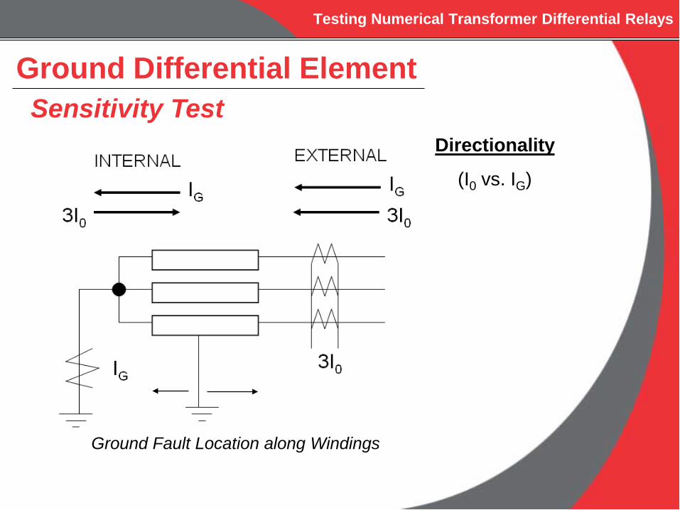
Ground Differential ElementSensitivity Test
Directionality
(I0 vs. IG)
Ground Fault Location along Windings

Testing Numerical Transformer Differential Relays
Ground Differential ElementDirectional Element
+90o
-90o
IGI0
Disabled if |3I0| less than 140 mA(Improves Security for CT saturation during external faults)
Internal External
Testing Numerical Transformer Differential Relays
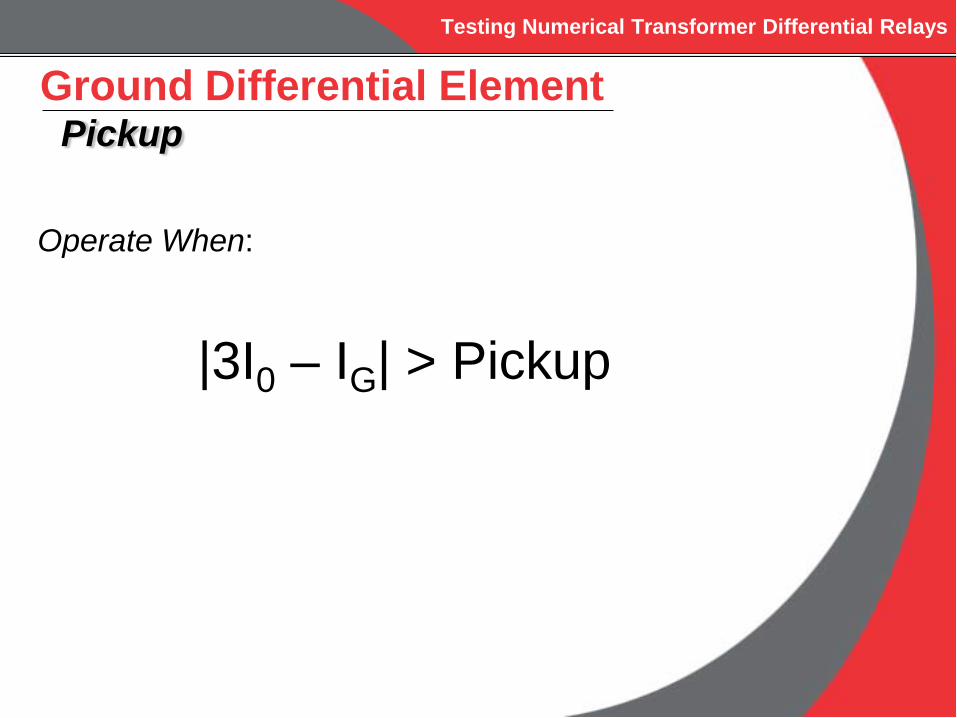
Ground Differential ElementPickup
Operate When:
|3I0 – IG| > Pickup

Testing Numerical Transformer Differential Relays
Ground Differential ElementSensitivity Test
Power System Parameters:•Source Impedance (Varies)•XT = 10%•RF (Varies)•Ground Fault Location (5% from Transformer Neutral)

Testing Numerical Transformer Differential Relays
87GD Sensitivity
0
20
40
60
80
100
120
140
160
180
0 20 40 60 80 100 120
Source Impedance
Faul
t Res
ista
nce
IG = 200 mA IG = 500 mA IG = 1 Amp
Ground Differential ElementRF Coverage vs. Source Strength

Testing Numerical Transformer Differential Relays
Ground Differential ElementPickup Setting
Cold Load PickupReclosing into Single-Phase Load
Pickup > UnbalanceDirectional Element Disabled if 3I0 Low
IG
R
Testing Numerical Transformer Differential Relays
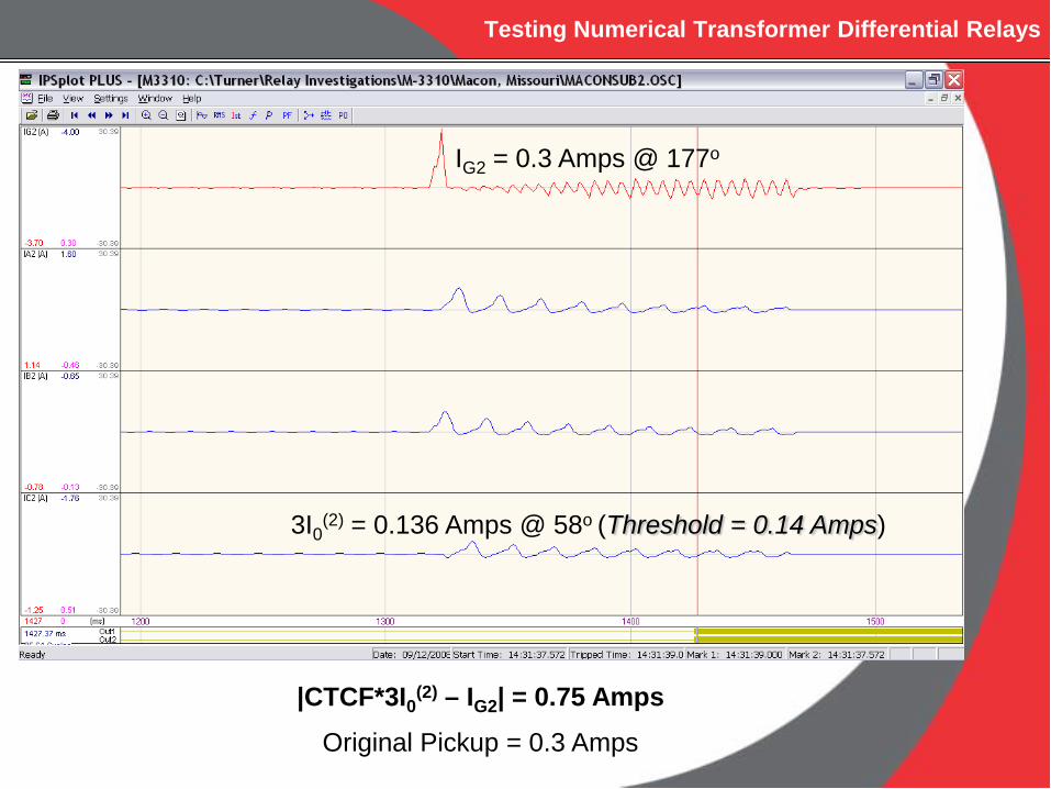
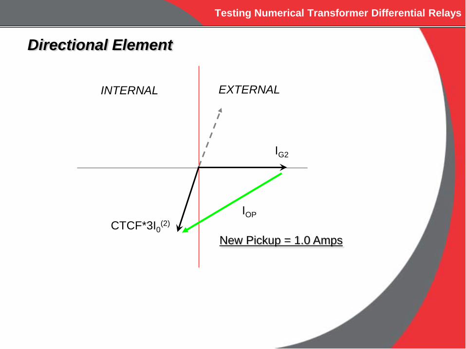
IG2 = 0.3 Amps @ 177o
3I0(2) = 0.136 Amps @ 58o (Threshold = 0.14 Amps)
|CTCF*3I0(2) – IG2| = 0.75 AmpsOriginal Pickup = 0.3 Amps
Testing Numerical Transformer Differential Relays
IG2
CTCF*3I0(2)
INTERNAL EXTERNAL
IOP
New Pickup = 1.0 Amps
Directional Element
Testing Numerical Transformer Differential Relays
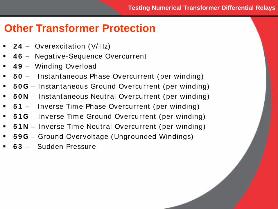
24 – Overexcitation (V/Hz) 46 – Negative-Sequence Overcurrent 49 – Winding Overload 50 – Instantaneous Phase Overcurrent (per winding) 50G – Instantaneous Ground Overcurrent (per winding) 50N – Instantaneous Neutral Overcurrent (per winding) 51 – Inverse Time Phase Overcurrent (per winding) 51G – Inverse Time Ground Overcurrent (per winding) 51N – Inverse Time Neutral Overcurrent (per winding) 59G – Ground Overvoltage (Ungrounded Windings) 63 – Sudden Pressure
Other Transformer Protection
Testing Numerical Transformer Differential Relays
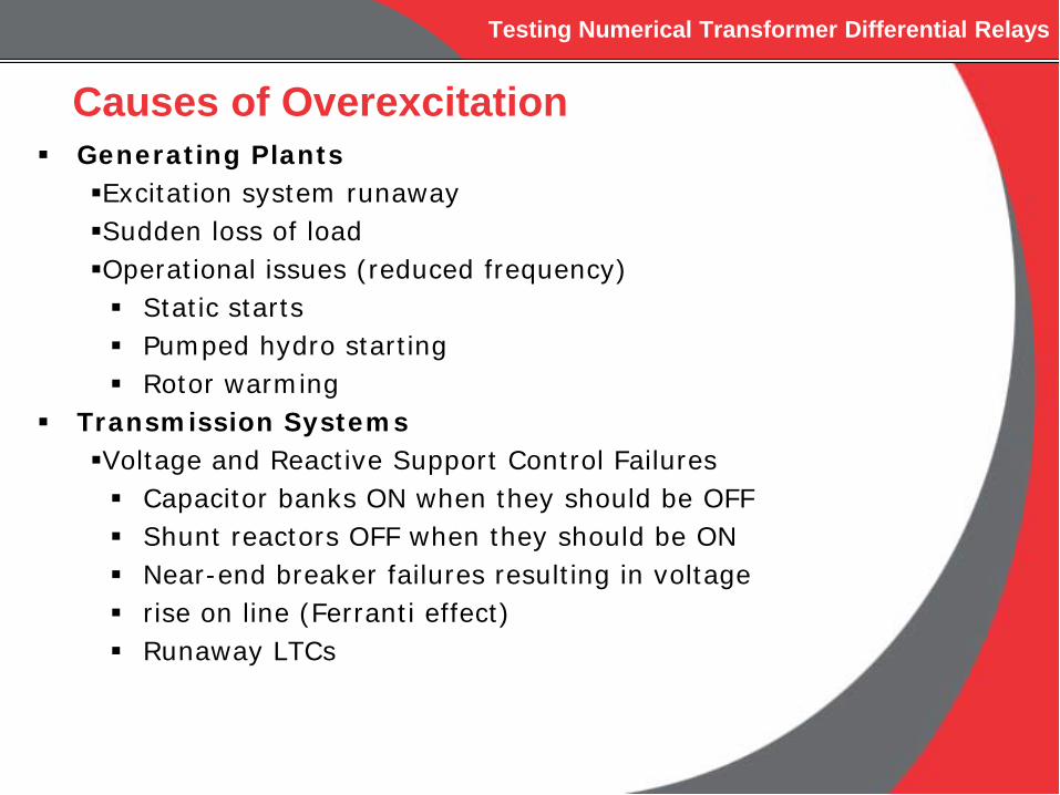
Generating PlantsExcitation system runawaySudden loss of loadOperational issues (reduced frequency) Static starts Pumped hydro starting Rotor warming
Transmission SystemsVoltage and Reactive Support Control Failures Capacitor banks ON when they should be OFF Shunt reactors OFF when they should be ON Near-end breaker failures resulting in voltage rise on line (Ferranti effect) Runaway LTCs
Causes of Overexcitation
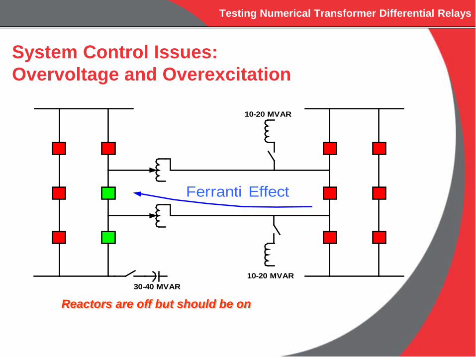
30-40 MVAR
10-20 MVAR
10-20 MVAR
Ferranti Effect
System Control Issues:Overvoltage and Overexcitation
Reactors are off but should be on
Testing Numerical Transformer Differential Relays
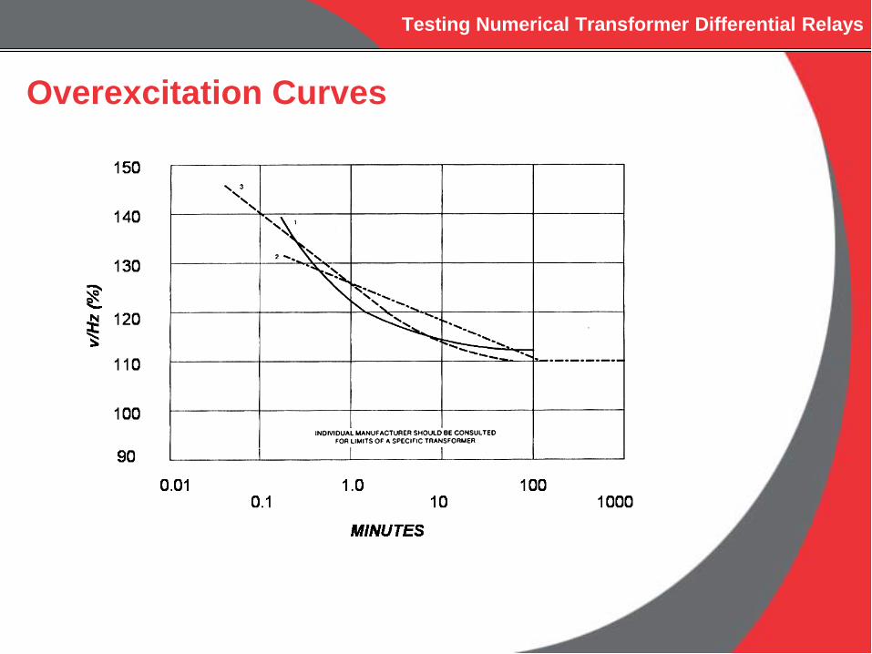
Overexcitation Curves
Testing Numerical Transformer Differential Relays
Testing Numerical Transformer Differential Relays
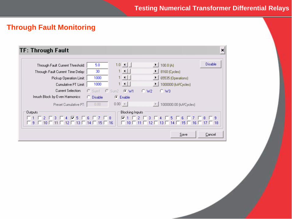
Through Fault Monitoring
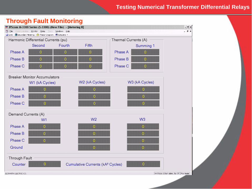
Testing Numerical Transformer Differential Relays
Through Fault Monitoring

Testing Numerical Transformer Differential Relays
Even Harmonic Restraint during InrushCOMTRADE PLAYBACK
Waveform Sources:•Events from Numerical Relays•Events from Digital Fault Recorders•Simulate using Transient Software

Testing Numerical Transformer Differential Relays
Even Harmonic Restraint during InrushTraditional Approach
•2nd Harmonic Restraint•Cross Phase Blocking
Testing Numerical Transformer Differential Relays
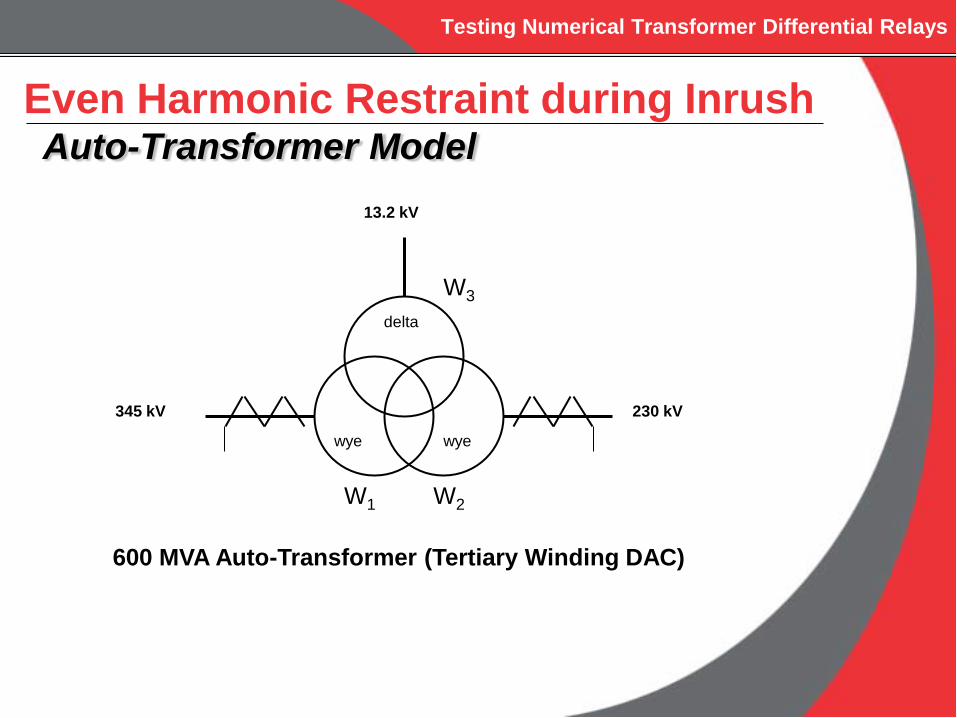
Even Harmonic Restraint during InrushAuto-Transformer Model
wye wye
delta
13.2 kV
345 kV 230 kV
W1 W2
W3
600 MVA Auto-Transformer (Tertiary Winding DAC)

Testing Numerical Transformer Differential Relays
Auto-transformer CharacteristicsZHM = 0.01073 per unitZHL = 0.04777 per unitZML = 0.03123 per unit
2MLHLHM ZZZ −+
= 0.0140 per unit
2HLMLHM ZZZ −+ = -0.0029 per unit
2HMMLHL ZZZ −+
CTRW1 = 1200:5 (wye connected)CTRW2 = 2000:5 (wye connected)
Even Harmonic Restraint during InrushAuto-Transformer Model
ZH =
ZM =
ZL = = 0.0340 per unit
Testing Numerical Transformer Differential Relays
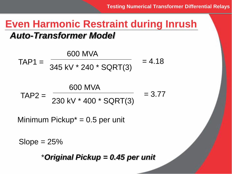
Even Harmonic Restraint during InrushAuto-Transformer Model
TAP1 =600 MVA
345 kV * 240 * SQRT(3)
TAP2 =600 MVA
230 kV * 400 * SQRT(3)
= 4.18
= 3.77
Minimum Pickup* = 0.5 per unit
Slope = 25%
*Original Pickup = 0.45 per unit
Testing Numerical Transformer Differential Relays
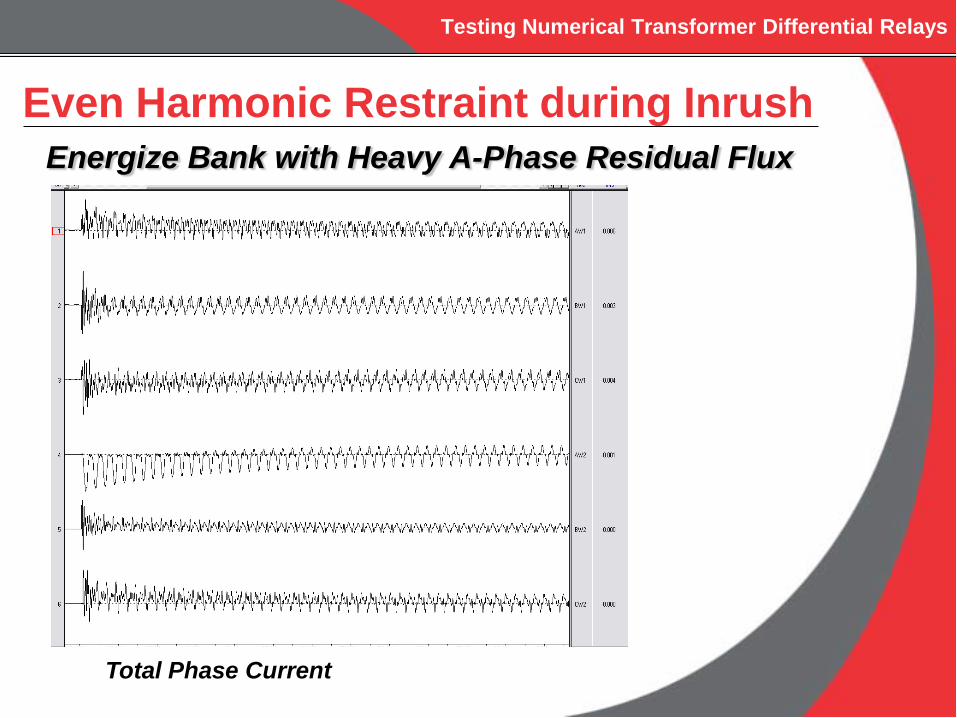
Even Harmonic Restraint during InrushEnergize Bank with Heavy A-Phase Residual Flux
Total Phase Current
Testing Numerical Transformer Differential Relays
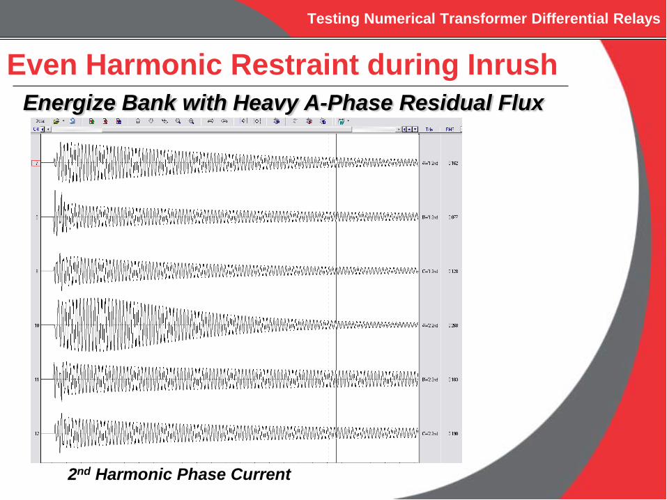
Even Harmonic Restraint during InrushEnergize Bank with Heavy A-Phase Residual Flux
2nd Harmonic Phase Current

Testing Numerical Transformer Differential Relays
Even Harmonic Restraint
Ieven = (I22 + I4
2)1/2

Testing Numerical Transformer Differential Relays
Provides security if any phase has low harmonic content during inrush
Cross phase averaging uses the sum of harmonics on all three phases as the restraint value
Cross Phase Averaging

Testing Numerical Transformer Differential Relays
Even Harmonic Restraint during InrushEnergize Bank with Heavy A-Phase Residual Flux
4th Harmonic Phase Current
Testing Numerical Transformer Differential Relays
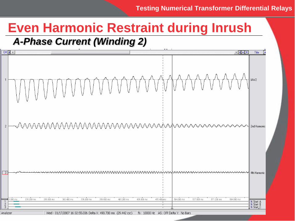
Even Harmonic Restraint during InrushA-Phase Current (Winding 2)
Testing Numerical Transformer Differential Relays
CONCLUSIONS
Testing Numerical Transformer Differential Relays
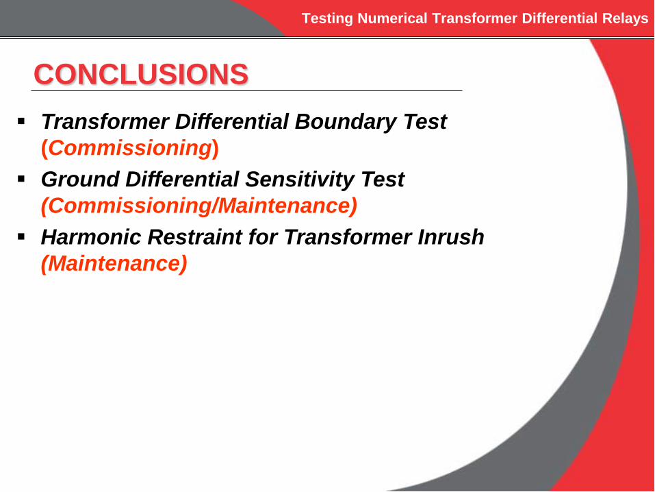
Transformer Differential Boundary Test(Commissioning)
Ground Differential Sensitivity Test(Commissioning/Maintenance)
Harmonic Restraint for Transformer Inrush(Maintenance)
CONCLUSIONS

Testing Numerical Transformer Differential Relays
QUESTIONS ?