1 · lightweight system is important, such as rocket leg deployment, mountain bike shocks and in...
27
www.scientistsinschool.ca 1
Transcript of 1 · lightweight system is important, such as rocket leg deployment, mountain bike shocks and in...

www.scientistsinschool.ca 1
www.scientistsinschool.ca 1
Fluid Power Legend tells us that Archimedes lowered himself into a bath and noticed that the water level rose. Realizing that his body displaced water, he then reportedly ran naked through the streets, shouting “Eureka”, to share his discovery with others. Displacement is only one aspect in the study of fluids, which also includes viscosity, density, buoyancy, Pascal’s law, hydraulics and pneumatics. Fluids are essential to all life, but are also important components of many systems, both natural and manufactured. The differences between fluids, and within a fluid under different conditions, determine how the fluids are utilized. Background Information Fluids A fluid, by definition, is a substance that has the ability to flow. Particle theory can help us understand this concept. First, let’s consider a solid whose particles are closely packed together allowing for some vibration but typically no net movement. This lack of particle movement means that solids are not fluids. Although some particles, such as those found in sand, will move as a group and appear to flow, individual grains have their own shape which does not change. In contrast, the particles in both liquids and gases are spread further apart and experience reduced intermolecular forces compared to solids, which allows for spatial movement of the particles. Therefore, both liquids and gases are fluids. Plasma is also a fluid but we will limit our discussion to liquids and gases. Another criterion used to define fluids is that they take the shape of their container. Viscosity Viscosity is a measure of a fluid’s ability to flow. A fluid with high viscosity, such as honey, flows more slowly than a fluid with low viscosity, like water. Temperature will affect the viscosity of a fluid. Generally, for a liquid, as the temperature increases, its viscosity decreases. As the temperature rises, the particles begin to move faster and their interactions are reduced, therefore the liquid can flow more freely. However, for a gas, an increase in temperature will result in an increase in viscosity. The gas particles also begin to move more quickly but in this case, they will start colliding with each other more frequently, which slows down the overall movement of the gas and increases its viscosity. All fluids have a viscosity integral to their nature. Physicists strive to engineer fluids that have the desired viscosity for an intended application. For example, if toothpaste is too viscous, then the user would not be able to get it out of the tube. If it was not viscous enough, then it would flow out of the tube once the cap was off and make a mess. If motor oil is not viscous enough, it would not properly coat the engine parts. If the viscosity of an adhesive is inappropriate for the application, then it would either not be sufficiently spreadable or it would not stay in place and stick the parts together. Density
Density is a measure of the mass per unit volume of a substance or in simpler terms, how many particles will fit into a given volume. For example, a one cubic centimetre marshmallow would weigh less than a one cubic centimetre stone. Although the volume of the two objects is the same, the mass is different. The marshmallow weighs less than a stone of the same volume and is, therefore, less dense. One major difference between liquids and gases is that liquids are far denser than gases as the molecules of liquids are closely packed together. Given this higher density, liquids are essentially incompressible. Gas can be readily compressed as there are empty spaces between the molecules.
www.scientistsinschool.ca 2
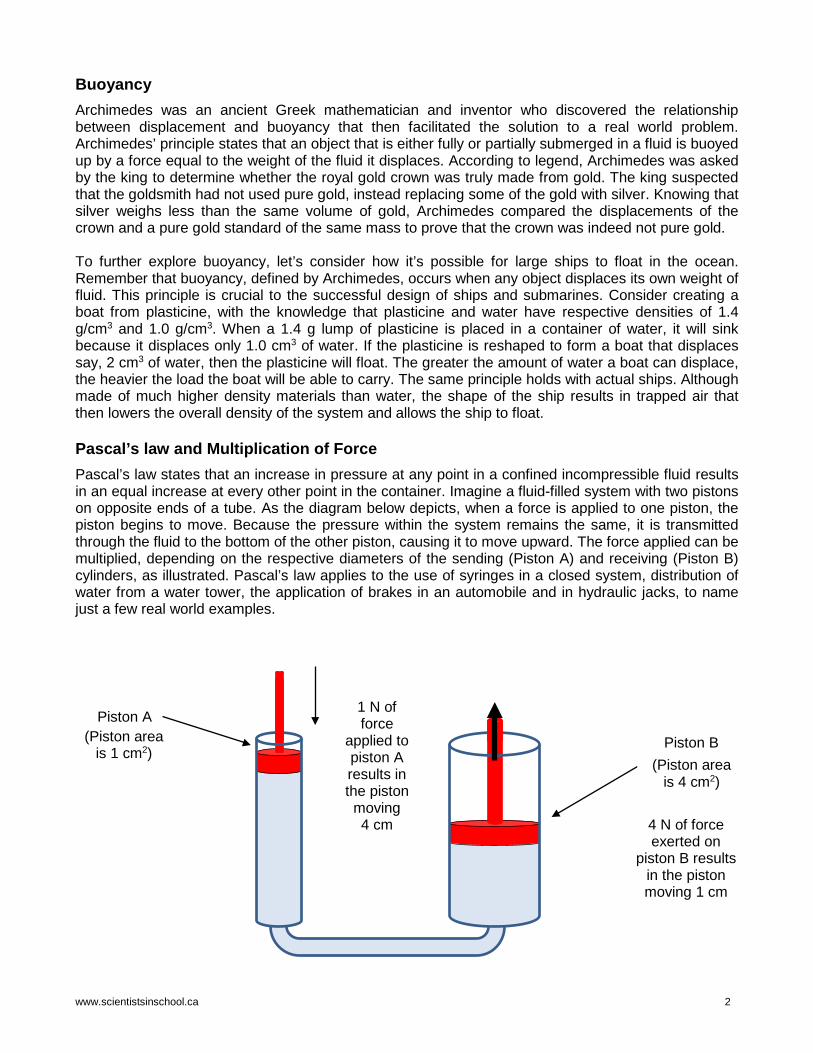
Buoyancy Archimedes was an ancient Greek mathematician and inventor who discovered the relationship between displacement and buoyancy that then facilitated the solution to a real world problem. Archimedes’ principle states that an object that is either fully or partially submerged in a fluid is buoyed up by a force equal to the weight of the fluid it displaces. According to legend, Archimedes was asked by the king to determine whether the royal gold crown was truly made from gold. The king suspected that the goldsmith had not used pure gold, instead replacing some of the gold with silver. Knowing that silver weighs less than the same volume of gold, Archimedes compared the displacements of the crown and a pure gold standard of the same mass to prove that the crown was indeed not pure gold. To further explore buoyancy, let’s consider how it’s possible for large ships to float in the ocean. Remember that buoyancy, defined by Archimedes, occurs when any object displaces its own weight of fluid. This principle is crucial to the successful design of ships and submarines. Consider creating a boat from plasticine, with the knowledge that plasticine and water have respective densities of 1.4 g/cm3 and 1.0 g/cm3. When a 1.4 g lump of plasticine is placed in a container of water, it will sink because it displaces only 1.0 cm3 of water. If the plasticine is reshaped to form a boat that displaces say, 2 cm3 of water, then the plasticine will float. The greater the amount of water a boat can displace, the heavier the load the boat will be able to carry. The same principle holds with actual ships. Although made of much higher density materials than water, the shape of the ship results in trapped air that then lowers the overall density of the system and allows the ship to float. Pascal’s law and Multiplication of Force Pascal’s law states that an increase in pressure at any point in a confined incompressible fluid results in an equal increase at every other point in the container. Imagine a fluid-filled system with two pistons on opposite ends of a tube. As the diagram below depicts, when a force is applied to one piston, the piston begins to move. Because the pressure within the system remains the same, it is transmitted through the fluid to the bottom of the other piston, causing it to move upward. The force applied can be multiplied, depending on the respective diameters of the sending (Piston A) and receiving (Piston B) cylinders, as illustrated. Pascal’s law applies to the use of syringes in a closed system, distribution of water from a water tower, the application of brakes in an automobile and in hydraulic jacks, to name just a few real world examples.
Piston A
Piston B (Piston area
is 4 cm2)
1 N of force
applied to piston A results in the piston moving 4 cm
(Piston area is 1 cm2)
4 N of force exerted on
piston B results in the piston moving 1 cm

www.scientistsinschool.ca 3
Hydraulic and pneumatic systems Hydraulic and pneumatic systems are both closed systems which operate under Pascal’s law. A hydraulic system is filled with a liquid while a pneumatic system is filled with a gas. Hydraulic systems, such as a hydraulic press, are preferable for high pressure applications given the essential incompressibility of a liquid. Hydraulic systems are used when the movement of heavy loads are required, such as by a crane or fork lift. The expansion and compression of gases within a pneumatic system, as well as condensation, can cause the system to behave unpredictably. These variables need to be considered for the system to function properly. A high pressure gas, usually compressed air, is used where a lightweight system is important, such as in rocket leg deployment, mountain bike shocks and racing vehicles. Pneumatic systems are also used where low loads/pressures are needed, like when suction is used to pick up small parts in a factory; when the compressible nature of the gas is desirable, such as shock absorption of pneumatic tires; or when objects need to be kept clean, as in the pneumatic transmission of money tubes in large warehouse stores.
Fun Fact: Safe Ships! The Plimsoll Line on a ship, also known as the
international load line, is a marking on the ship that indicates the lowest level at which a ship can maintain a safe buoyancy. It determines how much load a ship can
safely carry and shows safe load points according to the type of water (fresh versus salt) and season, as water
density changes with temperature and salt concentration.
Fun Fact: Safe Whales! Sperm whales have large cavities in their heads containing a substance called spermaceti. Some scientists believe that whales are capable of cooling or heating the spermaceti, thus affecting the whale’s density
and its ability to float or sink.

www.scientistsinschool.ca 4
Activity 1: Do You Know Your Fluid Principles?
Time: 30 minutes Key Terms: compressibility, Pascal’s law, buoyancy, viscosity Group size: Individual Materials for Class Demo: □ can of carbonated soda □ pen □ gloves □ safety glasses Materials (per student): □ “Do You Know Your Fluid
Principles? datasheet
Learning Goal: Students will learn about the principles governing the behaviour of fluids. Procedure: Class Demonstration 1. Review with students the four principles of fluids including
Pascal’s law, compressibility, buoyancy and viscosity. 2. Demonstrate Pascal’s law. With gloves and safety glasses on,
carefully place the full soda can on its side and puncture a small hole in the can with the pen. Drain approximately ¾ of the soda out of the can. Carefully twist and bend the can, taking care not to perforate the metal. Place your thumb over the hole and gently shake the can. As you do so, the carbon dioxide that is dissolved in the liquid will be released and the pressure inside the can will cause it to return to its original shape.
Student Activity 1. Hand out a “Do You Know Your Fluid Principles?” datasheet to
each student. Have students identify the principle(s) for each real-life situation involving fluids.
Observations: A sample completed datasheet is provided below:
Scenario P, B and/or V? Honey is more difficult to pour than water. Viscosity
A submarine can sink or float depending on how much ballast it has. Buoyancy
A metal cylinder is filled with propane and used with a barbeque. Pascal’s law
A small force applied to a brake pedal can stop a car. Pascal’s law
Water flows through a pipe, up and over the lip of a reservoir and down into a town’s water main.
Pascal’s law / Viscosity
Blood is able to flow through your vessels.
Viscosity / Pascal’s law (circulatory
system is closed) A hot air balloon rises as the air inside the balloon is heated. Buoyancy
The dashpot in a hydraulic door-closer slows the closing of a door to prevent it from slamming.
Viscosity/Pascal’s law (hydraulics rely on
Pascal’s law) A pneumatic nail gun can propel nails up to 425 metres/second. Pascal’s law
Discussion: Ask students if they can think of any other examples of these principles in everyday life.
Fun Fact: Safety First! Some mountain
roads in the Alps prohibit descending on bicycles. Friction
from rim braking can heat up the air in the tube inside
the tire which causes it to expand
and potentially burst the tube!

www.scientistsinschool.ca 5
Name:_________________
Do You Know Your Fluid Principles?
Scenario P, B and/or V?
Honey is more difficult to pour than water.
A submarine can sink or float depending on how much ballast it has.
A metal cylinder is filled with propane and used with a barbeque.
A small force applied to a brake pedal can stop a car.
Water flows through a pipe, up and over the lip of a reservoir and down into a town’s water main.
Blood is able to flow through your vessels.
A hot air balloon rises as the air inside the balloon is heated.
The dashpot in a hydraulic door closer slows the closing of a door to prevent it from slamming.
A pneumatic nail gun can propel nails up to 425 metres/second.
P = Pascal’s law: an increase in pressure, at any point in a confined incompressible fluid, results in an equal increase at every other point in the container.
B = Buoyancy: an object in a fluid, either partially or fully submerged, is buoyed up by a force equal to the weight of the fluid it displaces.
V = Viscosity: a measure of a fluid's resistance to flow.
www.scientistsinschool.ca 6
Activity 2: Water You “Up” To?
Time: 30 minutes Key terms: buoyancy, shear force, density Group size: Pairs Materials (per pair): □ 5 clear plastic cups or
glass beakers (300 mL capacity)
□ 200 mL clear corn syrup
□ 200 mL cool water
□ 200 mL vegetable oil
□ measuring cup or graduated cylinder
□ waterproof permanent marker
□ 100 mL 70% isopropyl alcohol
□ 3 drops dark colour food colouring (any colour except yellow)
□ 10 mL syringe
□ 15 cm plastic aquarium tubing to fit on syringe
□ 2 sheets unlined 8.5”x11” white paper
□ “Water You “Up” To” datasheet per student
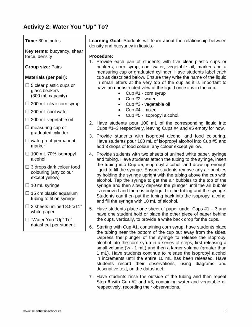
Learning Goal: Students will learn about the relationship between density and buoyancy in liquids. Procedure: 1. Provide each pair of students with five clear plastic cups or
beakers, corn syrup, cool water, vegetable oil, marker and a measuring cup or graduated cylinder. Have students label each cup as described below. Ensure they write the name of the liquid in small letters at the very top of the cup as it is important to have an unobstructed view of the liquid once it is in the cup.
• Cup #1 - corn syrup • Cup #2 - water • Cup #3 - vegetable oil • Cup #4 - mixed • Cup #5 - isopropyl alcohol.
2. Have students pour 100 mL of the corresponding liquid into Cups #1–3 respectively, leaving Cups #4 and #5 empty for now.
3. Provide students with isopropyl alcohol and food colouring. Have students pour 100 mL of isopropyl alcohol into Cup #5 and add 3 drops of food colour, any colour except yellow.
4. Provide students with two sheets of unlined white paper, syringe and tubing. Have students attach the tubing to the syringe, insert the tubing into Cup #5, isopropyl alcohol, and draw up enough liquid to fill the syringe. Ensure students remove any air bubbles by holding the syringe upright with the tubing above the cup with alcohol. Tap the syringe to get the air bubbles to the top of the syringe and then slowly depress the plunger until the air bubble is removed and there is only liquid in the tubing and the syringe. Students can then put the tubing back into the isopropyl alcohol and fill the syringe with 10 mL of alcohol.
5. Have students place one sheet of paper under Cups #1 – 3 and have one student hold or place the other piece of paper behind the cups, vertically, to provide a white back drop for the cups.
6. Starting with Cup #1, containing corn syrup, have students place the tubing near the bottom of the cup but away from the sides. Depress the plunger of the syringe to release the isopropyl alcohol into the corn syrup in a series of steps, first releasing a small volume (½ - 1 mL) and then a larger volume (greater than 1 mL). Have students continue to release the isopropyl alcohol in increments until the entire 10 mL has been released. Have students record their observations, using diagrams and descriptive text, on the datasheet.
7. Have students rinse the outside of the tubing and then repeat Step 6 with Cup #2 and #3, containing water and vegetable oil respectively, recording their observations.
www.scientistsinschool.ca 7
8. For Cup #4, students will be preparing a density column. Have students pour 80 mL of corn syrup into the cup, and then add 80 mL of water by pouring the water gently and slowly into the centre of the cup. Add 80 mL of vegetable oil the same way to the top of the water. Have students repeat Step 6 using this cup and record their observations.
Observations: Students should have recorded similar observations to those listed in the table. The coloured isopropyl alcohol layers in Cup #4 were lighter in colour than the pure isopropyl alcohol and food colour mixture in Cup #5. If students were observant, they would also notice that the isopropyl alcohol remained spherical in shape as it travelled through the oil layer. In comparison, students will observe that in corn syrup and water, the isopropyl alcohol created fascinating shapes as it travelled through the liquid to the top of the container. Cup #1 - Corn Syrup Cup #2 - Water Cup #3 - Vegetable Oil Cup #4 - Mixed
- Isopropyl alcohol sits on top of the liquid
- Isopropyl alcohol sits on top of the liquid
- Alcohol has partially mixed with the water, creating a fuzzy border between the layers
- Isopropyl alcohol sits on top of the liquid
- From bottom to top: corn syrup, water, a dark coloured layer of food colouring, vegetable oil and on top, a lightly coloured isopropyl alcohol layer
Discussion: This experiment demonstrates two important concepts that engineers need to understand when studying fluids: viscosity and buoyancy. The principle of buoyancy, whether something will float or sink, depends on the density of the object. Density is defined as the mass of a substance per unit volume. If an object is less dense than water, it will float in water. This is called positive buoyancy. If it is denser than water, then it will sink. This is called negative buoyancy. In Cup #4, students were able to see four distinct layers form, from bottom to top: corn syrup, water, vegetable oil and isopropyl alcohol. Students were able to create this column due to the differing densities as listed below:
Substance Density (g/mL) at room temperature Corn Syrup 1.4 g/mL
Water 1.0 g/mL Vegetable Oil 0.9 g/mL
Isopropyl Alcohol 0.8 g/mL
Another factor which affects the layering is the viscosity of the liquids. The corn syrup is the densest liquid in the column and it is much more viscous than the water. Rather than mixing and dissolving in water quickly, the corn syrup forms the bottom layer of the column. If the column was left to stand, then over time, the food colouring, water and corn syrup would mix together as these substances are miscible. Oil and water are not miscible and oil is less dense than water, thus the oil will float on the water layer. Isopropyl alcohol is not soluble in oil and is the least dense so it creates the top layer. Shear force, or shear stress, is the friction caused between two fluid particles due to their viscosity. If you push sideways on a solid object, like a table, it will not change shape and will resist the push until you use enough force to move it. In a fluid, when you push sideways, the liquid will move and change shape as a result of the push. When soluble liquids of different viscosities are added together, fun and interesting shapes may be observed as they mix. The liquid starts out as a sphere but the friction between the particles creates more of a pill shape followed by a plume of liquid. If the added liquid is

www.scientistsinschool.ca 8
less dense, as in the case of isopropyl alcohol, it will change shape as it rises through the more dense liquid. Alcohol is hydrophilic and will not mix with the oil. In this experiment, the isopropyl alcohol stays in a spherical shape as it floats through the oil. In contrast, as the isopropyl alcohol travels through corn syrup and water, both of which are miscible with isopropyl alcohol, the alcohol droplets assume fascinating shapes as a result of shear forces, which are forces that act perpendicular to the surface of the droplet. These forces minimize the interaction between the two liquids. Students should also notice that as the isopropyl alcohol travelled up through the density column, most of the food colouring remained behind in the water layer and collected near the upper surface of this layer. This is a result of the preferential solubility of food colouring in water, as compared to isopropyl alcohol. If left for a long period of time, the food colouring would diffuse throughout the water as a result of random molecular motion.
Fun Fact: How Does Viscosity Affect Volcanic Eruptions?
The viscosity of magma, or molten rock, under the Earth’s surface, is an important factor in determining whether a volcanic eruption will be explosive or non-
explosive. The viscosity of magma depends on temperature, composition and gas content. Low-viscosity magma tends to result in calm, nonviolent extrusions of lava, as it flows easily up from magma chambers and out
of the volcano. This type of magma allows dissolved gases to escape to the surface easily. Thicker, highly viscous magma tends to trap this gas and prevents its upward
movement. The pressure rises within the magma column until the gas ejects explosively from the volcano. This
type of volcanic eruption often has catastrophic consequences, as was experienced during the eruption of
Mount St. Helens in 1980.

www.scientistsinschool.ca 9
Name:__________________________
Water You “Up” To?
Corn Syrup Water Vegetable Oil Mixed
Cup #1 Cup #2 Cup #3 Cup #4
www.scientistsinschool.ca 10
Activity 3: Water Flow Rates
Time: 1 hour Key term: pressure, flow rate Group size: 3 students Materials (teacher preparation of bottles): □ push pin
□ screw
□ carriage bolt or large screw
Materials (per group): □ 3 empty 2L bottles with
0.2, 0.5 and 1.0 cm diameter holes
□ 2L capacity wide mouthed bowl
□ measuring cup with pour spout
□ masking tape
□ duct tape
□ timer
□ paper towels
□ water
□ “Water Flow Rates” datasheet (per student)
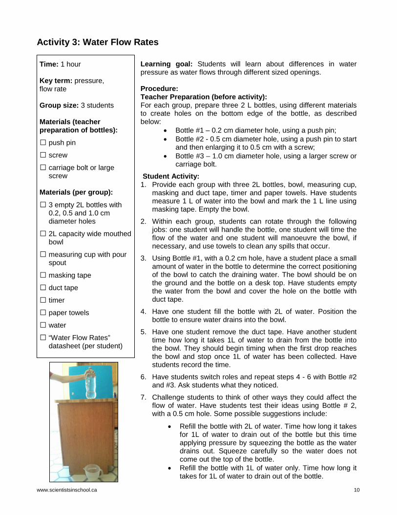
Learning goal: Students will learn about differences in water pressure as water flows through different sized openings. Procedure: Teacher Preparation (before activity): For each group, prepare three 2 L bottles, using different materials to create holes on the bottom edge of the bottle, as described below:
• Bottle #1 – 0.2 cm diameter hole, using a push pin; • Bottle #2 - 0.5 cm diameter hole, using a push pin to start
and then enlarging it to 0.5 cm with a screw; • Bottle #3 – 1.0 cm diameter hole, using a larger screw or
carriage bolt. Student Activity:
1. Provide each group with three 2L bottles, bowl, measuring cup, masking and duct tape, timer and paper towels. Have students measure 1 L of water into the bowl and mark the 1 L line using masking tape. Empty the bowl.
2. Within each group, students can rotate through the following jobs: one student will handle the bottle, one student will time the flow of the water and one student will manoeuvre the bowl, if necessary, and use towels to clean any spills that occur.
3. Using Bottle #1, with a 0.2 cm hole, have a student place a small amount of water in the bottle to determine the correct positioning of the bowl to catch the draining water. The bowl should be on the ground and the bottle on a desk top. Have students empty the water from the bowl and cover the hole on the bottle with duct tape.
4. Have one student fill the bottle with 2L of water. Position the bottle to ensure water drains into the bowl.
5. Have one student remove the duct tape. Have another student time how long it takes 1L of water to drain from the bottle into the bowl. They should begin timing when the first drop reaches the bowl and stop once 1L of water has been collected. Have students record the time.
6. Have students switch roles and repeat steps 4 - 6 with Bottle #2 and #3. Ask students what they noticed.
7. Challenge students to think of other ways they could affect the flow of water. Have students test their ideas using Bottle # 2, with a 0.5 cm hole. Some possible suggestions include:
• Refill the bottle with 2L of water. Time how long it takes for 1L of water to drain out of the bottle but this time applying pressure by squeezing the bottle as the water drains out. Squeeze carefully so the water does not come out the top of the bottle.
• Refill the bottle with 1L of water only. Time how long it takes for 1L of water to drain out of the bottle.

www.scientistsinschool.ca 11
Observations: Students should have observed that changing the size of hole at the bottom of the bottle changed the time required for the water to flow out of the bottle. See the sample completed table below. The larger the hole, the less time it should take for the water to flow out. As the bottle is squeezed, students should have noticed no appreciable difference in the time required to drain. When students only put 1L of water in the bottle, they should have observed that the time for the water to drain approximately doubled.
Experimental Condition
Time for 1 L of water to drain 0.2cm 0.5cm 1.0cm
2L 16min 15 sec 51 sec 17 sec
2L (with pressure) 49 sec
1L 1min 40 sec
Discussion: Once the opening is exposed, gravity and the pressure of the water cause the water to drain out of the bottle. When the hole at the bottom of the bottle is bigger, then a larger volume of water is able to flow out in the same amount of time. Why is there no appreciable difference when we apply pressure to the bottle? This may seem counterintuitive because when pouring a drink, you would observe that applied pressure decreases the time it takes for a glass to fill. However, when a bottle is tipped to pour, the full diameter of the spout is not used. In this example, when pressure is applied to a bottle, the fluid fills a larger portion of the spout therefore decreasing the time it takes for the liquid to pour. For this experiment, the full diameter of the hole is already being used as the liquid drains out. This is why the applied pressure does not decrease the time it takes for the water to pour out of the bottle. Now, let’s think about the difference in flow rate when there is only 1L of water in the bottle. We are draining the same amount of liquid, so why has our time essentially doubled? Within a column of water, the pressure is greatest at its lowest point, meaning that the more water there is in our bottle, the greater the pressure when we first remove the tape. With 2L of water in the bottle, the liquid above the water applies more pressure to the water below and enables it to drain faster. Students may be able to relate this to swimming in a pool. As a swimmer dives into the deep end, there is more pressure on their body. As a result, they may feel pain in their ears due to this difference in pressure. Your body wants to equalize the pressure and you can do this by ‘popping’ your ears. In a deep ocean, human bodies are not able to tolerate these higher pressures and thus divers wear equipment to protect their bodies. Ask students if they think manufacturers of soft drink bottles considered these flow rates when designing their bottles. Of course! This is a very important element in any design, from soft drink bottles to hydraulic systems.
Extensions: 1. Have students put 1L of water in a 1L bottle. Does anything change if you use different shaped
bottles (1L ketchup bottle vs 1L soft drink bottle)? 2. Instead of starting with a bottle filled with water, have students pour the water in as the water is
draining. How long does this take to fill 1L? 3. Have students use liquids with different viscosities, such as vegetable oil or corn syrup. Are there
any differences observed?

www.scientistsinschool.ca 12
Name:_________________
Water Flow Rates
Experimental Condition
Time for 1 L of water to drain
0.2cm hole 0.5cm hole 1.0cm hole
2L of water

www.scientistsinschool.ca 13
Activity 4: Pump It Up!
Time: 40 minutes Key Terms: pressure, compressibility, average Group Size: 3 students Materials (per group): □ pump water gun with a
trigger
□ water
□ sidewalk chalk
□ measuring tape
□ “Pump It Up!” datasheet
□ bucket and refill cup
□ graph paper
Learning Goal: Students will learn about the relationship between fluids and pressure. Many years ago, water guns had a small water reservoir and a very short range. Today’s water guns launch water a greater distance and have a larger reservoir which allows more time between refilling. The pump action of a water gun is both fun and a great tool for learning about fluids under pressure.
Procedure: 1. Take your class outside on a dry day with little wind. Have a
student from each group fill the water gun before proceeding outside. Bring a bucket of water and a cup, for refilling as needed. Find an area for each group in the schoolyard or on the sidewalk.
2. Provide each group with a datasheet, sidewalk chalk and measuring tape. Each member of the group will rotate through the following three jobs: Recorder, Measurer and Pumper.
3. Using the chalk, have the Recorder draw a line on the pavement. Have the Pumper stand with their toes on the line facing a long paved area.
4. Have the Pumper pump the water gun with half a pump and then use the trigger to spray the water. The Measurer will measure the distance the water travelled to the nearest centimetre. The Recorder will record the information on the “Pump it Up!” datasheet.
5. Have the Pumper vent the water reservoir by opening and closing the reservoir.
6. Have students repeat steps 4 -5, increasing the number of times they pump the gun: 1, 2, 4, 6, 8 times, and so on until the distance the water travels remains the same.
7. Have students replicate the experiment so that each student within the group has an opportunity to do each job.
8. In the classroom, have each group calculate an average distance travelled for each pump category. Have students graph the number of times pumped versus distance travelled for each student as well as the average.
Fun Fact: Water Balloon History In 1950, the English inventor Edgar Ellington was attempting to invent a waterproof sock to prevent trench foot by using cotton and latex. However, after filling his fabricated sock with water, he noticed a
leak. This discovery upset him so much that he threw the water-filled sock, which then burst and the idea of a water balloon was born!

www.scientistsinschool.ca 14
Observations: The following chart depicts sample observations. Results will vary depending on the type of water gun used. At some point, the distance travelled will reach a plateau and may even fall off, depending on various factors, as explained in the discussion section.
Number of Times Pumped
Distance Water Travelled (cm) Student 1 Student 2 Student 3 Average
½ 357 194 132 228
1 348 258 354 320
2 376 322 457 385
4 421 405 539 455
6 387 396 475 419
8 484 367 426
10 435 435
The following graph illustrates the results.
Discussion: Water guns are designed to generate pressure within a reservoir and push water out. The systems are structured differently with some water guns taking advantage of the compressibility of air versus the incompressibility of water. There are two types of water guns that use an air pressure system. Water gun A has a reservoir to store the water. Water gun B has a reservoir that holds the water but also an additional chamber that the user pumps water into, before firing the gun.
Water Gun A
Water Gun B
Additional Chamber
Water Reservoir
Pump

www.scientistsinschool.ca 15
Water Gun A: While pumping water gun A, air is being pushed from the atmosphere into the water reservoir. As the reservoir has a fixed volume and water is essentially incompressible, the air within the reservoir must compress each time the gun is pumped. This will create a pressurized system within the water gun.
Water Gun B: When water gun B is pumped, water is moved from the reservoir to the chamber. This chamber also has a fixed volume but is initially filled with air. As water moves into the chamber, the air must compress to make room for the water. The more water added, the more the air must compress.
As the air compresses inside each system, the volume that the air occupies decreases. This results in a direct increase in the pressure of the air. This higher pressure air is now pressing on the water inside the chamber or reservoir. The trigger keeps the system closed and holds the water inside. However, once the trigger is pressed, the system opens and the air inside the water gun attempts to equilibrate with the air in the atmosphere. The pressurized air therefore forces the water out. The more times the gun is pumped, the greater the pressure of air inside the chamber and the bigger the force used to expel the water. This is why the water will travel a greater distance as you proceed through the experiment. Eventually the system cannot compress any more air due to the size of the reservoir (gun A) or the chamber (gun B). At this point, you will typically see some water leak out of the system without depressing the trigger. This will usually happen more quickly with type A water guns than type B water guns. The water will not travel any further, as seen in the graph, because the system has reached its maximum pressure. In some cases, students may notice the distance dropping off before a maximum pressure has been reached. This can be due to the human error or an insufficient supply of water in the system, in which case the gun may need to be topped up. Compressed air is a powerful tool and we use it for many applications today. It is used to clean sensitive electronics, to fill the tires in our vehicles and within some powerful pneumatic systems, such as air brakes on a truck. Extensions:
1. Have students experiment with different types of water guns. How do the different styles of water guns compare with each other?
2. Have students repeat the activity. Each time the system is opened to vent, have them refill the reservoir with water. Are there any differences? Water gun A would have a noticeable difference as less space for the air means more compression and a bigger force on the water.
3. Have students repeat the experiment without venting the water reservoir between firing and pumping again. Water gun B would show no difference as the chamber is separate from the reservoir. Water gun A may build-up more compressed air and students may see the water travelling a further distance with fewer pumps.
4. Have students repeat the activity and explore what happens if the gun is held upside down. As water is denser than air, water guns are built to work with water at the bottom of the gun. Type B water guns will not work when the gun is upside down as the water inside the chamber would now be away from the firing mechanism. For type A water guns, it would depend on how much water is inside the reservoir. If the water level is high, there should only be a small difference in the results.
www.scientistsinschool.ca 16
Name(s):_________________ _________________ _________________
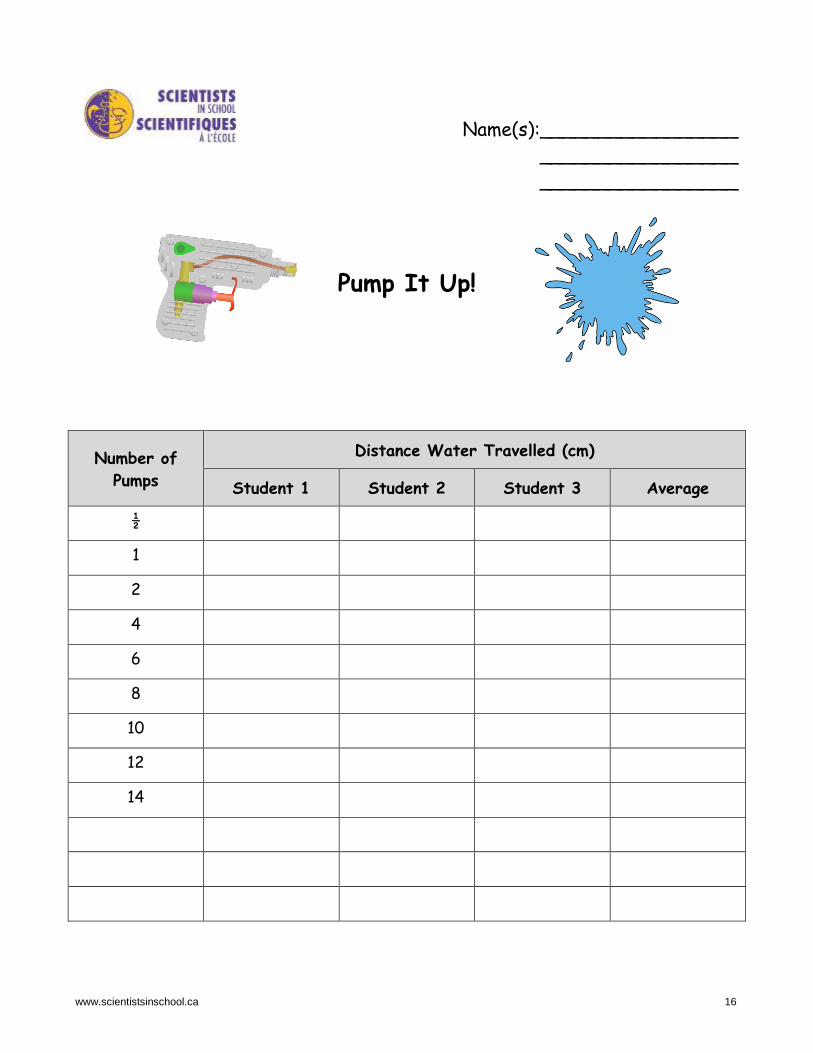
Pump It Up!
Number of Pumps
Distance Water Travelled (cm)
Student 1 Student 2 Student 3 Average
½
1
2
4
6
8
10
12
14

www.scientistsinschool.ca 17
Activity 5: Build a Battle Bot!
Time: several hours Key Term: hydraulic Other Application: Math Group size: 2-4 students Materials (per group): □ hot glue gun with at least
3 glue sticks
□ masking tape
□ 50 craft sticks (11 cm x 1 cm)
□ scissors or craft knife for cutting craft sticks and bamboo skewers
□ 35 square craft beads or blocks/cubes with centre-drilled holes (1 - 2 cm)
□ 4 bamboo skewers (3 mm diameter)
□ 3 x 10 cm cable ties or duct tape
□ 4 x 10 mL syringes
□ 2 m vinyl tubing with 1/8” or 0.170” ID (inside diameter)
□ small container filled with water
Learning Goal: Students will learn how to use hydraulics to create a moving wooden robot. Students may come up with their own designs for creating a robot while they go through the building process. The following website provides ideas on building hydraulic machines: http://www.instructables.com/id/Easy-Hydraulic-Machines/ (21/03/2017) Procedure: 1. Provide students with an overview of what they will be creating.
Each group will be making a Bot (short for robot) that consists of four different parts: 1) base, 2) stand, 3) arm and 4) hydraulic systems to make it move. The groups will then test their Bots by having a battle with another Bot.
2. Provide each group with a set of materials and instruct students that they can create a Bot with a base no larger than 25 cm x 25 cm. The following instructions for creating a Bot can be used as a guide and do not need to be followed verbatim.
Part 1: Base Construction The base is composed of a flat area as well as a platform that the Bot will stand on. 3. Using masking tape, measure out a 25 cm x 25 cm square
working space on the desk top. The base of the Bot will fit in this space.
4. Using the hot glue and craft sticks, create a base that fits inside the square. A triangle will make a stronger shape than a square. The craft sticks can be cut to fit if necessary.
5. Determine the front and the back of the structure. Approximately 6 cm from the centre back of the base, build a platform that will support the stand later on.
front
platform at back 6 cm
25 cm x 25 cm working space
Steps 3 – 5: Creating the Base

www.scientistsinschool.ca 18
3 cm
Step 6: Creating platform
Step 7: Main Support Stand
6. Create the platform for the Bot to stand on. Stack the centre beads (four pink beads in photo) vertically with holes facing the top so that in the following steps, the skewer from the Bot can be inserted into them. The height of the platform should be about 3 cm. Reinforce the outside of the centre beads by gluing support beads (12 blue beads in photo) around it.
Part 2: Stand Construction The stand consists of three separate parts: the main support stand, the horizontal control pivot, and the vertical pivot. 7. To build the main support stand, string two beads
(green beads in photo) on a skewer. If the fit is tight, sand the skewer until the beads slide on it easily. Glue one bead to one end of a craft stick (orange craft stick in photo) and glue the other bead to the other end of the same craft stick. Glue another craft stick to another face of the beads, until all faces are covered. The result will be a rectangular column with a skewer running through it. Set aside.
8. To build the horizontal control pivot, cut a craft stick (green craft stick in photo) in half and glue a bead (yellow bead in photo) to the rounded end of one half. Glue the other half of the craft stick to the opposite side of the bead.
9. To build the vertical pivot, string two beads (yellow beads in photo) on a skewer. Cut two craft sticks in half (blue sticks in photo) to create four pieces. Glue one end of each half craft stick on opposite sides of each bead. Repeat for the other bead. Glue a bead at the other end of each pair of half craft sticks. This results in two pivot pieces hanging from the skewer by the beads.
10. To assemble the stand, glue the open end of the horizontal control pivot (green sticks in photo) to the outside of the craft sticks at the bottom of the main support stand (orange sticks in photo). The sticks of the horizontal control pivot may have to be spread a bit to make it wide enough to get around the main support stand.
11. Glue the non-skewered beads of the vertical pivot (yellow beads between blue sticks in photo) to the outside of the craft sticks at the other end of the main support stand. Be sure to glue the beads on the same crafts sticks (orange sticks in photo) that the horizontal control pivot is glued to.
12. Reinforce the stand by gluing additional craft sticks (red sticks in photo), from the horizontal control pivot to the vertical pivot.
Step 9: Vertical Pivot
Step 8: Horizontal Control Pivot
Steps 10-12: Assembling the Stand
Step 10
Step 12 Step 11

www.scientistsinschool.ca 19
Part 3: Arm Construction 13. The main section of the arm should be 3 craft sticks long. Create the first half of the arm by
overlapping the ends of two craft sticks and gluing in place. Repeat by overlapping a third craft stick at the end of the assembly (red sticks in photo).
14. Create the other half of the arm by repeating with three more craft sticks. Join these halves by gluing beads between them (light blue beads in photo).
15. Glue a bead between the arm lengths at one end, making sure the hole is facing up with the sticks on either side (purple bead in photo).
16. Create a stop for the back end of the arm so
that it does not go back past the vertical pivot during assembly and cause the structure to fall backwards. Lay one stick flat on another one and join by gluing at one end (green sticks in photo). Let cool. Glue the open ends to the outsides of the arm above the last bead (purple bead in photo). You may have to bend, but not break, the sticks to achieve this.
17. Build an arm extension by laying one stick flat on
another one and join by gluing at one end only (green sticks in photo). Let cool. Glue together the open ends of the main section of the arm (red sticks in photo). Glue the open end of the arm extension to the glued ends of the main section of the arm (green to red sticks in photo).
18. Create a point on the end of the arm. This is used
to get under the opponent’s Bot to try and knock it over during the Battle of the Bots. Cut a craft stick in half (orange sticks in photo). Cut a 5 cm piece from the sharp end of a skewer. Glue it between the two ends of the cut craft stick (orange sticks in photo).
19. Cut a 2 cm piece of skewer and glue to one craft stick under the end (orange stick in photo). Glue
the point onto the main section of the arm (orange to green sticks in photo). Part 5: Hydraulic Systems for Horizontal and Vertical Movement Two hydraulic systems will be built. One system will be for used for horizontal movement of the Bot and the second system will be for vertical movement. 20. Cut two 60 cm lengths of vinyl tubing. Fill a container with water. 21. Depress the plunger on one of the syringes as far as it will go. Put the open end of the syringe
under the level of the water in the container. Pull up on the plunger to fill syringe to the 10 mL mark. Push one end of the vinyl tubing over the open end of the syringe. Holding the open end of
Step 16: Create Stop for Back End of Arm
Step 17 – 19: Create Arm Extension
Step 17 Step 18
Step 19
Step 13 -15 Main Section of Arm Step 15
Step 14
Step 13

www.scientistsinschool.ca 20
the tubing over the container, depress the plunger to empty it of water thus emptying the air from the tubing. Put the open end of the tubing under the surface of the water and pull up on the plunger until it reaches the 10 mL mark. Depress the plunger in a second syringe all the way. Remove the tubing from the water and push it onto the end of the second syringe.
22. Test the hydraulic system to ensure that the opposing plunger moves when the other plunger is depressed. If the plungers don’t have a full range of motion (0 to 10 mL), experiment with adding and removing water from the hydraulic assembly until the full range of motion is achieved.
23. Depending on the length required, glue a bead or two to the top of one plunger in each assembly, making sure the hole is facing out (green beads in photo).
24. Repeat step 21 - 23 to create a second hydraulic system using the other two syringes and piece of tubing.
Part 6: Final Assembly of Bot The base, stand, arm and two hydraulic systems are joined together to form the Bot. 25. Place the skewer that runs through the column of the main
support stand into the stand holder on the platform of the base (pink beads in photo). Make sure the main support stand is resting at the bottom of the hole in the stand holder.
26. Remove the skewer from the beads in the vertical pivot (skewer was between two yellow beads in photo).
27. Trim the top of the skewer in the main support stand so that it is halfway up the height of the vertical pivot.
28. Place the back end of the arm between the two member pieces
of the vertical pivot on the stand and thread a skewer through the three beads to join the arm to the stand (two yellow beads in vertical pivot of the stand and one purple bead of the arm in the photo). Trim the skewer so that about 1 cm of the skewer extends from each side.
Step 28
Step 25 – 27: Assembling Stand to Base
Step 26
Step 25
Step 28: Assembling Arm to Stand
Step 20 – 24: Building Hydraulic System
Step 23
Step 27

www.scientistsinschool.ca 21
29. Take one of the hydraulic systems and depress
the bead end of the plunger to the 5 mL mark. Place a short piece of skewer (about 6 cm) through the bead on the horizontal pivot and a bead on the top of the syringe (yellow bead of horizontal pivot and green beads on plunger in the photo).
30. Holding the syringe in place, test the horizontal movement by depressing and pulling out the plunger on the free end. There should be about the same amount of movement from one side to the other. If there isn’t, reposition the syringe and try again. When there is the same range of motion left to right, secure the beaded syringe to the base using a cable tie and layered craft sticks and/or beads to stabilize it.
31. Take the second hydraulic system and depress the bead end of the plunger to the 10 mL mark. Raise the arm so it is at its most vertical position. Secure the syringe to the main arm with a cable tie through the hole in the bead attached to the plunger (green bead to red craft stick of main arm in photo).
32. Hold the syringe under the arm against the stand and depress and pull out the plunger on the free end to test the vertical range of motion. Adjust the height of the beaded syringe against the column so that when the tip of the arm rests on the desk, the beaded plunger is at the bottom of its stroke. Secure the hydraulic system for vertical movement in place with a cable tie.
33. If there are any craft sticks left over, reinforce the base by layering craft sticks and/or creating more triangles.
34. Test the horizontal and vertical motion of the Bot. Ensure that the syringes are mounted so that the full range of motion is achieved and make adjustments if necessary.
35. Using one student on each set of hydraulics, practice controlling the Bot. Part 7: Battle of the Bots! Time to test the Bots and see how they perform! 36. Pair up groups to battle against each other’s Bots. Place each Bot on the desk facing each other
such that they are 5 to 10 cm apart (depending on the length of the arm). Ensure that they are about 15 cm from the edge of the desk.
37. Using only the hydraulics, each team will manipulate their own Bot to battle the other. A win can occur in one of two ways: a Bot is knocked over or a Bot malfunctions (i.e. one team experiences a hydraulic failure). A tie occurs if both Bots are knocked over.
Step 29-30: Adding Hydraulic System #1 for Horizontal Movement of Bot
Step 29 Step 30
Step 31
Step 31-32: Adding Hydraulic System #2 for Vertical Movement of Bot
Step 32
www.scientistsinschool.ca 22
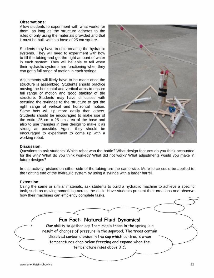
Observations: Allow students to experiment with what works for them, as long as the structure adheres to the rules of only using the materials provided and that it must be built within a base of 25 cm square. Students may have trouble creating the hydraulic systems. They will need to experiment with how to fill the tubing and get the right amount of water in each system. They will be able to tell when their hydraulic systems are functioning when they can get a full range of motion in each syringe. Adjustments will likely have to be made once the structure is assembled. Students should practice moving the horizontal and vertical arms to ensure full range of motion and good stability of the structure. Students may have difficulties with securing the syringes to the structure to get the right range of vertical and horizontal motion. Some bots will tip more easily than others. Students should be encouraged to make use of the entire 25 cm x 25 cm area of the base and also to use triangles in their design to make it as strong as possible. Again, they should be encouraged to experiment to come up with a working robot. Discussion: Questions to ask students: Which robot won the battle? What design features do you think accounted for the win? What do you think worked? What did not work? What adjustments would you make in future designs? In this activity, pistons on either side of the tubing are the same size. More force could be applied to the fighting end of the hydraulic system by using a syringe with a larger barrel. Extension: Using the same or similar materials, ask students to build a hydraulic machine to achieve a specific task, such as moving something across the desk. Have students present their creations and observe how their machines can efficiently complete tasks.
Fun Fact: Natural Fluid Dynamics! Our ability to gather sap from maple trees in the spring is a
result of changes of pressure in the sapwood. The trees contain dissolved carbon dioxide in the sap which contracts when temperatures drop below freezing and expand when the
temperature rises above 0°C.

www.scientistsinschool.ca 23
Teacher Resources Literary Resources The Nature of Matter. 2007. Anna Clayborne. Gareth Stevens Publishing. ISBN: 9780836880977. An introduction to the science of solids, liquids and gases. Matter (Discovery Channel School Science: Physical Science). 2003. Sharon Yates, Jacqueline A. Ball and Discovery Channel. Gareth Stevens Publishing. ISBN: 0836833619. Easy to do experiments and good descriptions of matter as it changes states. Website Resources http://www.nfpa.com/fluidpower/whatisfluidpower.aspx (21/03/2017) A website with a definition of fluid power including information on hydraulics and pneumatics. https://www.teachengineering.org/lessons/view/pur_fluidpower_less1 (21/03/2017) A detailed and comprehensive overview of fluid power. http://www.teachengineering.org/view_lesson.php?url=collection/pur_/lessons/pur_fluidpower_less1/pur_fluidpower_less1.xml#objectives (21/03/2017) A complete lesson plan for the fluid power unit. http://www.chem.purdue.edu/gchelp/liquids/character.html (21/03/2017) Introduction to particle theory. http://www.juliantrubin.com/encyclopedia/physics/buoyancy.html (21/03/2017) Experiments exploring the concepts of buoyancy, density and specific gravity. http://phet.colorado.edu/en/simulation/buoyancy (21/03/2017) Lesson plans and simulations on buoyancy. http://www.grc.nasa.gov/WWW/k-12/WindTunnel/Activities/Pascals_principle.html (21/03/2017) An explanation of Pascal’s law as it pertains to hydraulics, with examples and sample exercises. http://www.cscscientific.com/csc-cientific-blog/bid/101944/Viscosity-Basics-For-Those-of-Us-Who-Aren-t-Scientists (21/03/2017). A good explanation of viscosity. http://www.chem1.com/acad/webtext/states/liquids.html (21/03/2017) Informative website on liquids and their interfaces including viscosity. http://www.chem4kids.com/files/matter_plasma.html (21/03/2017) Information on plasma and links to other states of matter. Interactive White Board Resources “The Particle Theory” http://exchange.smarttech.com/details.html?id=de0635f9-1ac9-4547-bb47-1933b18064cc (21/03/2017). Learn how to use the particle theory to explain the properties of solids, liquids and gases. “Water Displacement” http://exchange.smarttech.com/details.html?id=cf34a042-dcf2-4405-83e0-7cbdfa0541e9 (21/03/2017) Fundamentals and applications of water displacement.
www.scientistsinschool.ca 24
“Density and Buoyancy” http://exchange.smarttech.com/details.html?id=477474f2-b320-4a47-b6ab-9d6a1666c690 (21/03/2017) Review the property of matter called density, what the buoyancy force is and how density is related to buoyancy. Multi-media https://www.youtube.com/watch?v=977wNbFiYlc 5:57 min. (21/03/2017) Demonstration of viscosity. https://www.youtube.com/watch?v=ChK1en0pxi0 3:05 min. (21/03/2017) Archimedes’ principle. https://www.youtube.com/watch?v=pnIlE1xD-yM 3:04 min. (21/03/2017) Why do ships float? Student Resources Literary Resources Floating and Sinking. Peter Riley. 2001. Gareth Stevens Publishing. ISBN 0-8368-3248-5. Provides a simple introduction to buoyancy. Canals and Dams: Investigate Feats of Engineering. Donna Latham. 2013. Nomad Press. ISBN 978-1-61930-169-6. Provides an in-depth look at fluid power and includes a number of hands-on activities. Solids, liquids and gases. Louise Oborn and Carol Gold. 1998. Kids Can Press. ISBN: 9981550744011, 1550741950. An introduction to the science of solids, liquids and gases. Interactive Websites http://science.howstuffworks.com/transport/engines-equipment/hydraulic.htm (21/03/2017) An in-depth, partially interactive, look at hydraulic systems. http://quizlet.com/23237028/4c-compare-solids-liquids-and-gases-in-terms-of-compressibility-structure-shape-and-volume-s-flash-cards/ (21/03/2017) An interactive website for learning and testing the concepts of particle theory. http://sge.wonderville.ca/pipelines/index.html (21/03/2017) A good interactive resource about fluid flow in a pipeline. https://www.wisc-online.com/learn/career-clusters/stem/hyp4307/comparing-hydraulics-and-pneumatics (21/03/2017) An interactive slideshow showcasing an overview of the similarities and differences between hydraulic and pneumatic systems. References In addition to resources listed above, the following websites were also used to develop this package: http://animals.nationalgeographic.com/animals/mammals/sperm-whale/ (07/04/14); http://en.wikipedia.org/wiki/Spermaceti (07/04/14); http://maple.dnr.cornell.edu/produc/sapflow.htm (07/04/14); http://en.wikipedia.org/wiki/Waterline (07/04/14) www.mne.psu.edu/cimbala/Learning/Fluid/Introductory/what_is_fluid_mechanics.htm (15/07/16); https://www.teachengineering.org/activities/view/cub_flow_activity1 (15/07/16); http://entertainment.howstuffworks.com/water-blaster1.htm (12/07/16); http://www.sscentral.org/physics/works.html (12/07/16); http://scienceprimer.com/boyles-law (12/07/16); http://www.compairusa.com/Resources/Education/Compressed_Air_Explained.aspx (12/07/16); http://www.cagi.org/working-with-compressed-air/applications.aspx (12/07/16); http://www.siliconesandmore.com/en/products/plasticine.html (27/07/16); http://www.historyofballoons.com/balloon-facts/facts-about-water-balloons/ (04/08/16); http://www.bloodflowonline.com/learn-about-blood-viscosity/blood-viscosity-basics (20/09/16); http://www.geology.sdsu.edu/how_volcanoes_work/Controls.html (19/10/16); http://www.wisegeek.org/what-is-viscosity.htm (19/10/16).

Get kids excited about science
Science Education Through Partnership Scientists in School is a leading science education charity that reaches more Kindergarten to Grade 8 youth than any other science non-profit in Canada – 670,000 in the 2016-17 school year. Through our hands-on, inquiry-based science, technology, engineering, math (STEM) and environmental classroom and community workshops, we strive to ignite scientific curiosity in children so that they question intelligently; learn through discovery; connect scientific knowledge to their world; get excited about science, technology, engineering and math; and have their interest in careers in those fields piqued. By making science a verb - something you do - our workshops allow children’s natural curiosity to reign, inspire kids to see themselves as scientists and engineers, and make connections between science and the world around them. This sets the stage for a scientifically-literate future generation who will fuel Canada’s economic prosperity and think critically about the scientific challenges facing our society. Scientists in School relies upon corporate, community, government and individual donors, as well as school board partners for support to develop new programs, continuously improve our existing programs, reach new geographic areas, provide complimentary workshops to less-privileged schools, and subsidize the cost of every one of our 24,800 annual classroom workshops.
Our Partners Catalyst Level:
Natural Sciences and Engineering Research Council (NSERC), TD Friends of the Environment Foundation, Toronto Pearson International Airport
Innovation Level:
Google Canada, John and Deborah Harris Family Foundation, Nuclear Waste Management Organization, RBC Foundation
Imagination Level:
Amgen Canada, Amgen Foundation, McMillan LLP, Ontario Power Generation Superior Glove Works Ltd., TELUS
Discovery Level:
Cameco, Celestica, Community Foundation of Ottawa, J.P. Bickell Foundation Isherwood Associates, MilliporeSigma, Purdue Pharma, Syngenta, Systematix Inc., The J.W. McConnell Family Foundation,
The Maurice Price Foundation, The McLean Foundation
Exploration Level: Ajax Community Fund at Durham Community Foundation, Consulting Engineers of Ontario, Huronia
Community Foundation Isherwood Associates, Lee Valley Tools, Meridian Credit Union, Rotary Club of Lethbridge, Siemens Milltronics Process Instruments,
The Optimist Club of Ajax, Veridian Connections, Whitby Mayor’s Community Development Fund
[email protected] – www.scientistsinschool.ca Scientists in School is a registered Canadian charity: #867139537RR0001


![3 Pappus’, Desargues’ and Pascal’s Theoremsmath2.uncc.edu/~frothe/3181alleuclid1_3.pdfIn Hilbert’s foundations [22], this theorem is named after Pascal. Pascal’s Pascal’s](https://static.fdocuments.in/doc/165x107/5ac266c87f8b9a1c768dea9e/3-pappus-desargues-and-pascals-frothe3181alleuclid13pdfin-hilberts.jpg)