1 Survey of ICIC Techniques in LTE Networks under … 2015/2015_05_04... · under Various Mobile...
30
1 Survey of ICIC Techniques in LTE Networks under Various Mobile Environment Parameters Mohamad Yassin ‡* , Mohamed A. AboulHassan § , Samer Lahoud ‡ , Marc Ibrahim * , Dany Mezher * , Bernard Cousin ‡ , Essam A. Sourour ** ‡ University of Rennes 1, IRISA, Campus de Beaulieu, 35042 Rennes, France * Saint Joseph University of Beirut, ESIB, CST, Mar Roukoz, Lebanon § Pharos University, Electrical Engineering Department, Alexandria, Egypt ** Prince Sattam Bin Abdul-Aziz University, Wadi Addawasir, Saudi Arabia Abstract LTE networks’ main challenge is to efficiently use the available spectrum, and to provide satisfying quality of service for mobile users. However, using the same bandwidth among adjacent cells leads to occurrence of Inter-cell Interference (ICI) especially at the cell-edge. Basic interference mitigation approaches consider bandwidth partitioning techniques between adjacent cells, such as frequency reuse of factor m schemes, to minimize cell-edge interference. Although SINR values are improved, such techniques lead to significant reduction in the maximum achievable data rate. Several improvements have been proposed to enhance the performance of frequency reuse schemes, where restrictions are made on resource blocks usage, power allocation, or both. Nevertheless, bandwidth partitioning methods still affect the maximum achievable throughput. In this proposal, we intend to perform a comprehensive survey on Inter-Cell Interference Coordination (ICIC) techniques, and we study their performance while putting into consideration various design parameters. This study is implemented throughout intensive system level simulations under several parameters such as different network loads, radio conditions, and user distributions. Simulation results show the advantages and the limitations of each technique compared to frequency reuse-1 model. Thus, we are able to identify the most suitable ICIC technique for each network scenario. Index Terms Inter-Cell Interference Coordination, mobile networks, LTE, frequency reuse-3, FFR, SFR.
Transcript of 1 Survey of ICIC Techniques in LTE Networks under … 2015/2015_05_04... · under Various Mobile...
1
Survey of ICIC Techniques in LTE Networks
under Various Mobile Environment Parameters
Mohamad Yassin‡∗, Mohamed A. AboulHassan§, Samer Lahoud‡, Marc Ibrahim∗,
Dany Mezher∗, Bernard Cousin‡, Essam A. Sourour∗∗
‡University of Rennes 1, IRISA, Campus de Beaulieu, 35042 Rennes, France∗Saint Joseph University of Beirut, ESIB, CST, Mar Roukoz, Lebanon§Pharos University, Electrical Engineering Department, Alexandria, Egypt∗∗Prince Sattam Bin Abdul-Aziz University, Wadi Addawasir, Saudi Arabia
Abstract
LTE networks’ main challenge is to efficiently use the available spectrum, and to provide satisfying
quality of service for mobile users. However, using the same bandwidth among adjacent cells leads
to occurrence of Inter-cell Interference (ICI) especially at the cell-edge. Basic interference mitigation
approaches consider bandwidth partitioning techniques between adjacent cells, such as frequency reuse
of factor m schemes, to minimize cell-edge interference. Although SINR values are improved, such
techniques lead to significant reduction in the maximum achievable data rate. Several improvements
have been proposed to enhance the performance of frequency reuse schemes, where restrictions are
made on resource blocks usage, power allocation, or both. Nevertheless, bandwidth partitioning methods
still affect the maximum achievable throughput. In this proposal, we intend to perform a comprehensive
survey on Inter-Cell Interference Coordination (ICIC) techniques, and we study their performance while
putting into consideration various design parameters. This study is implemented throughout intensive
system level simulations under several parameters such as different network loads, radio conditions,
and user distributions. Simulation results show the advantages and the limitations of each technique
compared to frequency reuse-1 model. Thus, we are able to identify the most suitable ICIC technique
for each network scenario.
Index Terms
Inter-Cell Interference Coordination, mobile networks, LTE, frequency reuse-3, FFR, SFR.
2
I. INTRODUCTION
Third Generation Partnership Project (3GPP) introduced Long Term Evolution (LTE) [1]
standard to fulfill the increasing demand for data in mobile networks. LTE is a mobile network
technology that substantially improves end-user throughputs [2], in order to meet the rapid
growth in data demands. With the proliferation of mobile applications and the development
of mobile equipment industry, mobile operators always seek to increase resource efficiency in
order to make maximum use of the scarce available frequency spectrum. LTE chooses frequency
reuse-1 model to improve system capacity and increase user satisfaction. Multiuser Orthogonal
Frequency Division Multiple Access (OFDMA) [3] technique used for the radio interface on
the downlink of LTE networks eliminates intra-cell interference, since data is transmitted over
independent orthogonal subcarriers. Similarly, Single Carrier Frequency Division Multiple Access
(SC-FDMA) technique, characterized by a lower peak-to-average power ratio [4], is used on the
uplink to transmit data from users to the base station [5]. However, frequency reuse factor
one leads to Inter-Cell Interference (ICI) strongly affecting SINR of active User Equipments
(UEs), especially cell-edge UEs, which leads to a significant degradation in the total throughput.
Moreover the existence of network elements with different maximum transmission power, e.g.,
macrocells, picocells and femtocells, makes the ICI problem more complicated.
ICI arises as a prohibitive problem due to simultaneous transmissions over the same frequency
resources in adjacent LTE cells. ICI decreases Signal-to-Interference plus Noise Ratio (SINR)
especially for cell-edge UEs [6], that are relatively far from the serving evolved-NodeB (eNodeB).
Thus, it has a negative impact on user throughput, it decreases spectrum efficiency, and it reduces
the quality of provided services.
Hard frequency reuse schemes (e.g., reuse factor m) become inefficient due to utilization of1m
of available bandwidth that affects peak data rate. For instance, adjacent base stations of a
Global System for Mobile communications (GSM) network are allocated different frequencies
[7] in order to avoid interference between neighboring transmitters. A number of adjacent GSM
cells are grouped into a cluster where the same frequency resources are used only once [8]. A
cluster size of one is not used due to high co-channel interference problems that occur. Although
ICI within each cluster is eliminated, spectral efficiency is largely reduced.
In Code Division Multiple Access (CDMA) scheme, the interference experienced by a user
3
is due to cross-correlation between spreading codes, and it can be considered as noise [9].
Therefore, ICI problems do not exist in CDMA-based 3G networks. OFDMA scheme [10] is
based on OFDM technology that subdivides the available bandwidth into a multitude of narrower
mutually orthogonal subcarriers, which can carry independent information streams. A physical
Resource Block (RB) is defined as 12 subcarriers in the frequency domain (180 kHz) and six
OFDM symbols in the time domain, which is equivalent to one time slot (0.5 ms) [11]. RB
and power allocation are performed periodically by the schedulers every Transmit Time Interval
(TTI) that equals one millisecond.
Although frequency reuse-m models eliminate ICI, they are not adequate for LTE networks.
In fact, one major objective of 3GPP LTE standard is to increase network capacity in order
to accommodate additional UEs. According to reuse-m schemes, each base station is allowed
to allocate a portion of the available spectrum. This restriction is not tolerated in LTE since
it greatly reduces spectrum efficiency. Thus, other frequency and power allocation schemes are
used to reduce ICI; they are commonly known as Inter-Cell Interference Coordination (ICIC)
[12] techniques.
Fractional Frequency Reuse (FFR) [13] and Soft Frequency Reuse (SFR) [14] are distributed
static ICIC techniques used to improve spectral efficiency of LTE. While FFR sets restrictions
on RB allocation between the different UEs in each cell, SFR performs both radio resource
management and power allocation for the used RBs. These techniques are independently used
in each cell without any cooperation between adjacent base stations. Several works exploit the
communications between adjacent eNodeBs to reduce ICI. In fact, signaling messages about
RB and power allocation are exchanged between adjacent eNodeBs over X2 interface, that
interconnects neighboring cells. For instance, a recently proposed technique divides ICIC problem
into a multi-cell scheduling and a multi-user scheduling problem [15]. The former uses an On/Off
approach to determine the restricted RBs for each evolved NodeB (eNodeB), while the latter
attributes RBs to UEs according to their radio conditions. ICIC can also be seen as a cooperative
problem where LTE base stations collaborate in order to find the power allocation mask that
minimizes inter-cell interference [16]. It is an adaptive SFR scheme that reduces transmission
power on RBs allocated for UEs that experience good radio quality (close to the base station).
However, the time scale of the proposed algorithm is in order of tens of seconds, which is
disadvantageous when the system state is quickly varying with time.

4
With the introduction of Coordinated Multi-Point (CoMP) transmissions [17] in LTE-Advanced
(LTE-A) networks, ICIC techniques rely more on dynamic coordination between base stations.
Scheduling decisions are improved when they are made jointly for a cluster of cells [18] thereby
enhancing performance through interference avoidance. Small cells (including pico-cells, femto-
cells and home eNodeBs) deployment [19] along with existing macro base stations brings out the
challenge of ICIC in heterogeneous networks. Indeed, serious interference [20] problems occur
due to co-channel deployments with the macro cells. Enhanced-ICIC (e-ICIC) techniques are
used to allow for time-sharing of spectrum resources between macro base stations and small cells.
Authors of [21, 22] surveyed the different ICIC techniques, and they classified them according
to cell cooperation and frequency reuse patterns. However, some of the existing ICIC surveys
only present qualitative comparisons [23] of ICIC techniques, while others perform simulations
under uniform UE distributions and ordinary network scenarios.
Given the diversity of existing ICIC techniques, mobile network operators have the opportunity
to implement the most convenient one for their intended objectives. In fact, the performance of
some techniques largely depends on network parameters such as UE distribution between cell
zones, existing ICI problems, and the number of UEs in each cell. Some techniques aim at
improving cell-edge UEs throughput, without taking into account the overall spectral efficiency.
Consequently, the knowledge of ICIC techniques performance is a critical factor when selecting
the one that best fits operator’s goals. In this article, we perform a comprehensive survey of
the performance of ICIC techniques in LTE Networks. Various network loads, radio conditions,
and user distributions are considered, in order to study the impact of design parameters on ICIC
techniques performance. We investigate the performance of frequency reuse-m model and other
ICIC techniques, and we classify them depending on the cooperation between network base
stations. A MATLAB-based LTE downlink system level simulator [24, 25] is used to compare
the performance of frequency reuse-1 model with reuse-3 model, FFR and SFR techniques. The
objective of ICIC is to reduce interference problems in order to avoid their harmful impact on
user throughput and system performance. An efficient ICIC technique improves both spectral
efficiency and energy efficiency of the mobile network, which is a substantial goal for mobile
network operators.
The rest of the article is organized as follows: in section II we explain frequency planning
techniques used in GSM networks, we discuss interference problems in LTE, and we classify
5
the existing ICIC techniques. Section III describes LTE system model, UE classification and
SINR calculation. Details about simulation environment and performance metrics are given in
section IV. Simulation results are reported in section V, and concluding remarks are presented
in section VI.
II. ICIC TECHNIQUES
A. Frequency Planning Techniques for GSM Networks
The goal of frequency planning in GSM is to increase the capacity of the network while
minimizing interference. After the first generation of analog mobile networks that use one single
antenna transmitting at the maximum power, frequency reuse technique along with the cellular
concept increase system capacity by allowing the usage of the same frequency resources in
adjacent GSM clusters. The idea is to decrease cell size by reducing base station downlink
transmission power in order to guarantee low co-channel interference.
Frequency allocation is planned taking into account the following issues: radio coverage,
interference estimation and traffic distribution [26]. Traditionally, adjacent GSM cells are grouped
into clusters where only a portion of the available spectrum is used in each cell. Therefore, we
reduce ICI since frequency resources are not simultaneously used by adjacent base stations. If
m is the number of cells within a cluster (also called: cluster size), then 1m
of the available
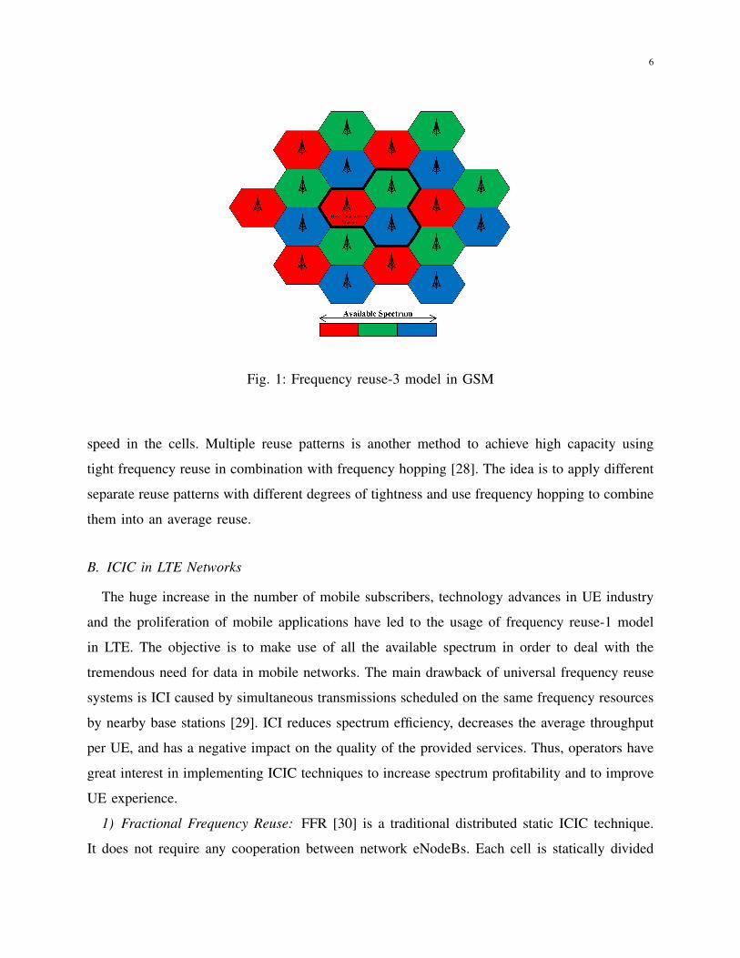
subcarriers are used in each cell according to frequency reuse-m model. Figure 1 illustrates a
GSM network where frequency reuse-3 model is used to manage frequency resources distribution
between the different cells.
Although frequency reuse-m model mitigates ICI, the main disadvantage of such technique is
that it reduces network capacity. With less resources available in each cell, the operator is not able
to accommodate all the existing UEs. Thus the quality of the provided services is degraded, and
user satisfaction is negatively impacted, especially when the number of UEs per cell increases.
A possible alternative is to reduce cluster size when the number of UEs or their generated traffic
increases. Thus, frequency planning in GSM can be seen as a compromise between network
capacity and interference mitigation.
A dynamic channel allocation strategy is introduced in [27] where authors use the information
exchanged between base stations in order to avoid conflicting carrier acquisitions. Frequency
allocation between the different cells is tuned in real time, based on the average traffic and UE
6
Fig. 1: Frequency reuse-3 model in GSM
speed in the cells. Multiple reuse patterns is another method to achieve high capacity using
tight frequency reuse in combination with frequency hopping [28]. The idea is to apply different
separate reuse patterns with different degrees of tightness and use frequency hopping to combine
them into an average reuse.
B. ICIC in LTE Networks
The huge increase in the number of mobile subscribers, technology advances in UE industry
and the proliferation of mobile applications have led to the usage of frequency reuse-1 model
in LTE. The objective is to make use of all the available spectrum in order to deal with the
tremendous need for data in mobile networks. The main drawback of universal frequency reuse
systems is ICI caused by simultaneous transmissions scheduled on the same frequency resources
by nearby base stations [29]. ICI reduces spectrum efficiency, decreases the average throughput
per UE, and has a negative impact on the quality of the provided services. Thus, operators have
great interest in implementing ICIC techniques to increase spectrum profitability and to improve
UE experience.
1) Fractional Frequency Reuse: FFR [30] is a traditional distributed static ICIC technique.
It does not require any cooperation between network eNodeBs. Each cell is statically divided
7
into cell-center and cell-edge zones. The former contains UEs close to the base station, while
the latter contains UEs close to the border of the cell. Since they are closer to the neighboring
cells and relatively far from their serving eNodeBs, cell-edge UEs will experience more ICI.
Therefore, the main objective of FFR is to protect RBs attributed for these UEs from interference
problems.
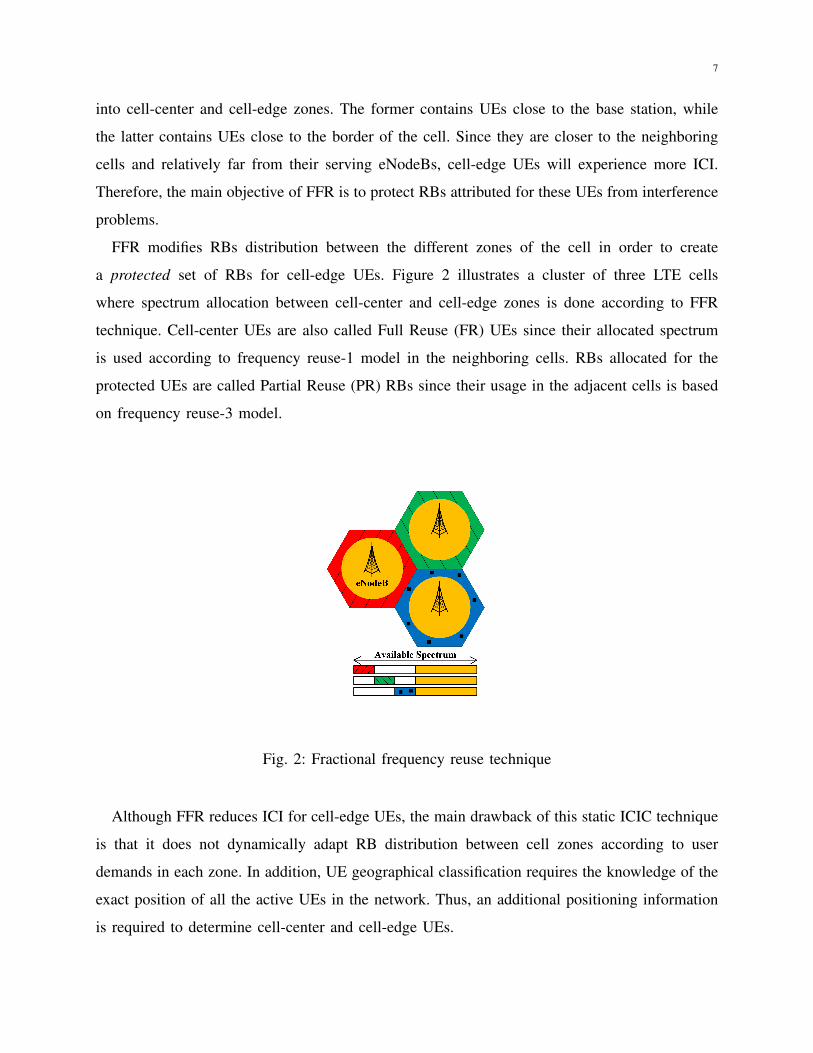
FFR modifies RBs distribution between the different zones of the cell in order to create
a protected set of RBs for cell-edge UEs. Figure 2 illustrates a cluster of three LTE cells
where spectrum allocation between cell-center and cell-edge zones is done according to FFR
technique. Cell-center UEs are also called Full Reuse (FR) UEs since their allocated spectrum
is used according to frequency reuse-1 model in the neighboring cells. RBs allocated for the
protected UEs are called Partial Reuse (PR) RBs since their usage in the adjacent cells is based
on frequency reuse-3 model.
Fig. 2: Fractional frequency reuse technique
Although FFR reduces ICI for cell-edge UEs, the main drawback of this static ICIC technique
is that it does not dynamically adapt RB distribution between cell zones according to user
demands in each zone. In addition, UE geographical classification requires the knowledge of the
exact position of all the active UEs in the network. Thus, an additional positioning information
is required to determine cell-center and cell-edge UEs.
8
2) Soft Frequency Reuse: In the downlink of a multiuser OFDMA system, such as LTE,
Signal to Interference and Noise Ratio (SINR) for a UE k on the RB n in the cell i is given by:
SINRik, n =
P in ·Gi
k, n∑j 6=i
P jn ·Gj
k, n + PTN
, (1)
where P in is the downlink transmission power allocated by the base station i for the RB n, Gi
k, n
is channel gain for UE k served by eNodeB i on RB n, and PTN is the thermal noise power on
the considered RB. The achievable rate on RB n for UE k in the cell i is therefore given by:
Rik, n = f(SINRi
k, n), (2)
where f(.) is the adaptive modulation and coding function that maps SINR to rate. SFR is
another static ICIC technique where both RB distribution and downlink power allocation are
performed to reduce ICI [31]. We define SINRi
k as the mean wideband SINR for UE k served
by eNodeB i. It is the mean value of SINRik,n for the considered UE over all the available RBs.
This entity gives us information about the average channel quality, radio conditions, and ICI
for UE k, since SINR is a function of the useful received power and the interfering received
power. Instead of using geographical positions, mean wideband SINR values are used to classify
UEs. If mean SINR of a UE is lower than a predefined SINR threshold, it is considered as a
Bad Radio (BR) conditions UE; otherwise, it is classified as Good Radio (GR) conditions UE.
BR UEs are commonly known as cell-edge UEs, while the remaining UEs are called cell-center
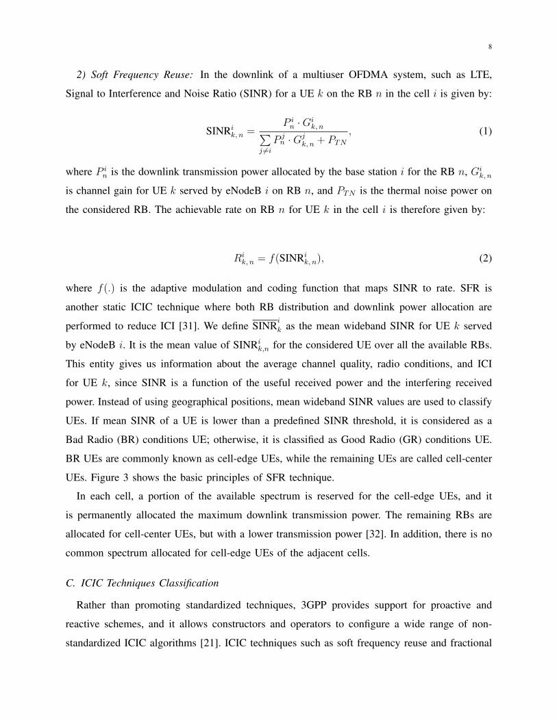
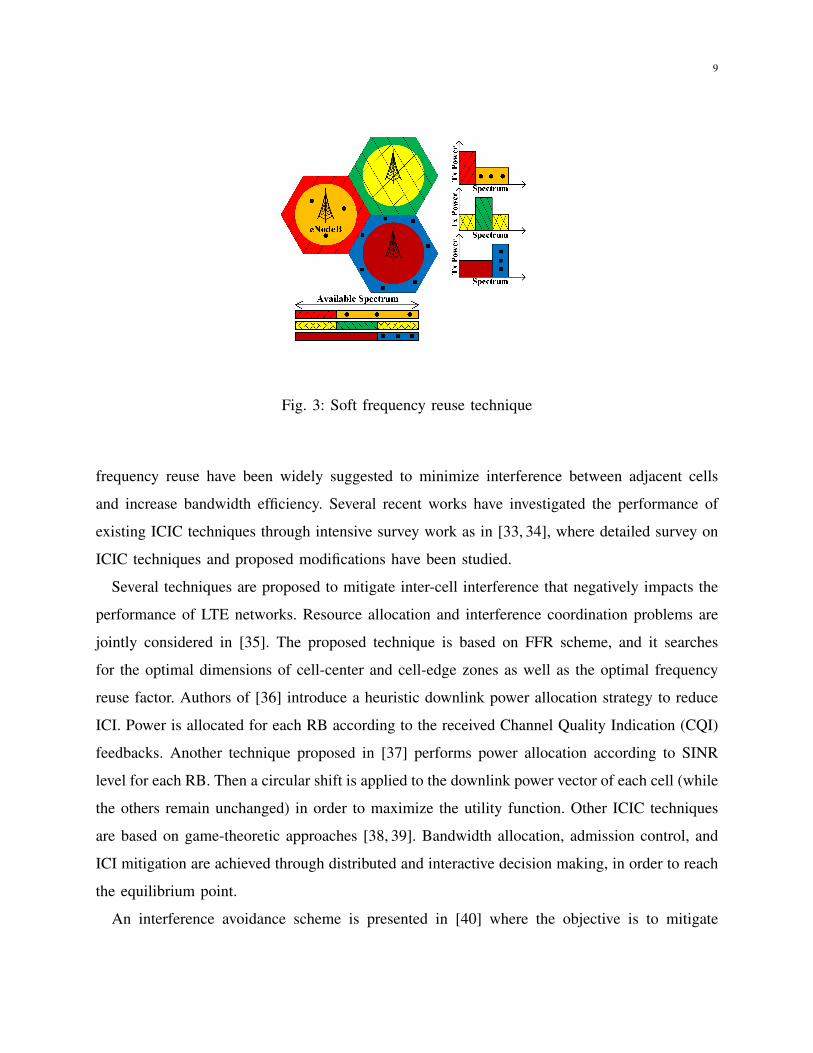
UEs. Figure 3 shows the basic principles of SFR technique.
In each cell, a portion of the available spectrum is reserved for the cell-edge UEs, and it
is permanently allocated the maximum downlink transmission power. The remaining RBs are
allocated for cell-center UEs, but with a lower transmission power [32]. In addition, there is no
common spectrum allocated for cell-edge UEs of the adjacent cells.
C. ICIC Techniques Classification
Rather than promoting standardized techniques, 3GPP provides support for proactive and
reactive schemes, and it allows constructors and operators to configure a wide range of non-
standardized ICIC algorithms [21]. ICIC techniques such as soft frequency reuse and fractional
9
Fig. 3: Soft frequency reuse technique
frequency reuse have been widely suggested to minimize interference between adjacent cells
and increase bandwidth efficiency. Several recent works have investigated the performance of
existing ICIC techniques through intensive survey work as in [33, 34], where detailed survey on
ICIC techniques and proposed modifications have been studied.
Several techniques are proposed to mitigate inter-cell interference that negatively impacts the
performance of LTE networks. Resource allocation and interference coordination problems are
jointly considered in [35]. The proposed technique is based on FFR scheme, and it searches
for the optimal dimensions of cell-center and cell-edge zones as well as the optimal frequency
reuse factor. Authors of [36] introduce a heuristic downlink power allocation strategy to reduce
ICI. Power is allocated for each RB according to the received Channel Quality Indication (CQI)
feedbacks. Another technique proposed in [37] performs power allocation according to SINR
level for each RB. Then a circular shift is applied to the downlink power vector of each cell (while
the others remain unchanged) in order to maximize the utility function. Other ICIC techniques
are based on game-theoretic approaches [38, 39]. Bandwidth allocation, admission control, and
ICI mitigation are achieved through distributed and interactive decision making, in order to reach
the equilibrium point.
An interference avoidance scheme is presented in [40] where the objective is to mitigate
10
interference for cell-edge UEs without reducing network throughput. The algorithm operates
at the base station level and at a central controller to which a group of base stations are
connected. Techniques based on interference graph approach are studied in [41, 42]. X2 interface
that connects each eNodeB to its neighboring cells is exploited to exchange information related
to interference levels, UE density, RB usage, and power allocation in each cell. They make use
of base station cooperation in order to reduce ICI, and to improve system throughput. A flexible
bandwidth allocation scheme for partial frequency reuse is described in [43] where RBs are
dynamically allocated for cell zones.
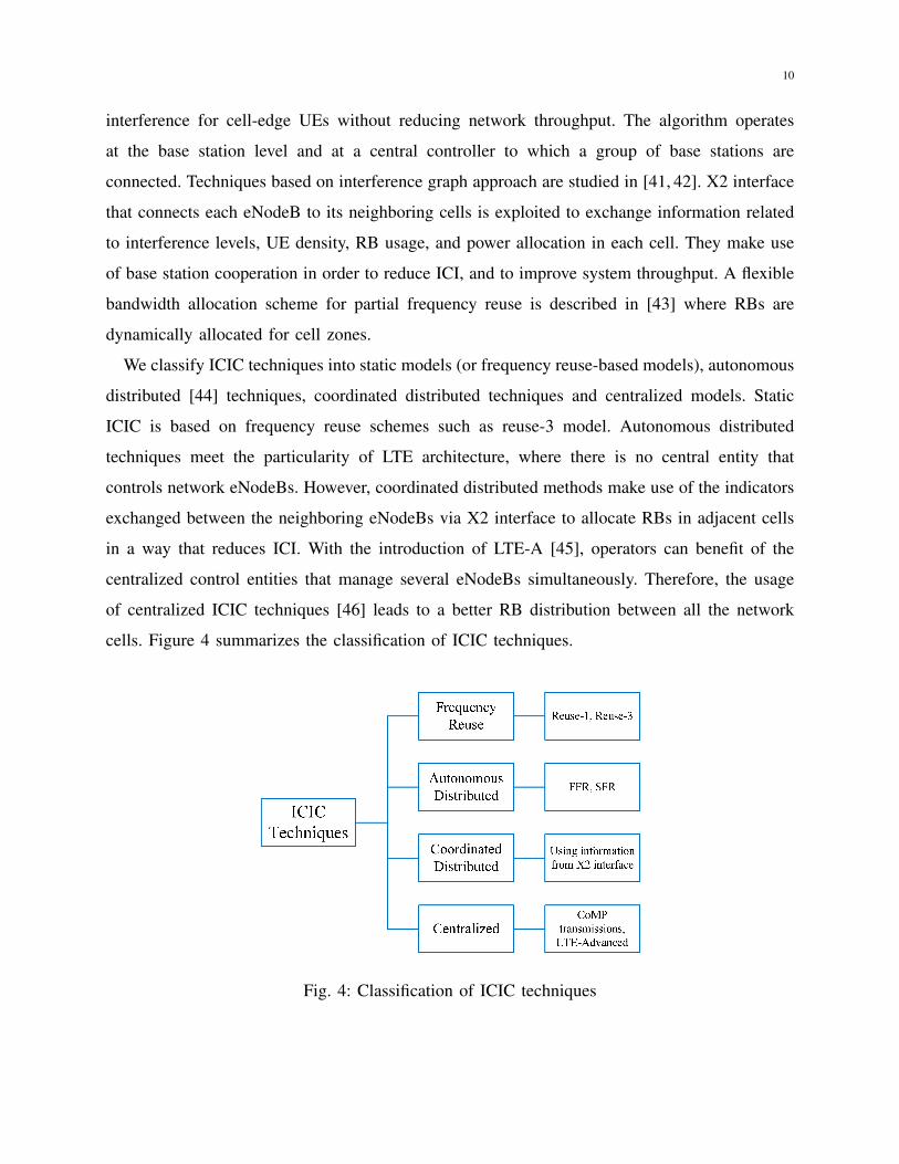
We classify ICIC techniques into static models (or frequency reuse-based models), autonomous
distributed [44] techniques, coordinated distributed techniques and centralized models. Static
ICIC is based on frequency reuse schemes such as reuse-3 model. Autonomous distributed
techniques meet the particularity of LTE architecture, where there is no central entity that
controls network eNodeBs. However, coordinated distributed methods make use of the indicators
exchanged between the neighboring eNodeBs via X2 interface to allocate RBs in adjacent cells
in a way that reduces ICI. With the introduction of LTE-A [45], operators can benefit of the
centralized control entities that manage several eNodeBs simultaneously. Therefore, the usage
of centralized ICIC techniques [46] leads to a better RB distribution between all the network
cells. Figure 4 summarizes the classification of ICIC techniques.
Fig. 4: Classification of ICIC techniques

11
D. CoMP Transmissions and Enhanced-ICIC
3GPP introduced coordinated multipoint transmission and reception techniques to facilitate
cooperative communications for LTE-A system [47]. In CoMP, several cells coordinate with
each other in such a way that the transmitted signals do not incur serious interference or even
can be exploited as a meaningful signal. CoMP techniques [48] target more dynamic interference
coordination, and they may require very low latency in comparison with ICIC techniques using
information carried over X2 interface (latency is not guaranteed to be low). For instance,
some techniques allow the transmission of the same data signals by different base stations
instead of transmitting interfering signals. System performance is therefore improved using joint
transmission, but additional signaling messages for base station coordination are required.
ICI problems in heterogeneous networks [49] arise as a new challenge with the extensive
deployment of small cells (including femto and pico cells). For instance, an optimal FFR scheme
for channel allocation is proposed in [50], where macrocell coverage is partitioned into cell-
center and cell-edge zones with six sectors in each zone. The available spectrum is allocated in
a manner that reduces co-tier interference in comparison with FFR. In addition, intracell cross-
tier interference is reduced. Interference mitigation techniques proposed for multi-cell multi-
antenna networks exploit cell cooperation to achieve coordinated scheduling [51], where RBs
are allocated in the different cells without causing serious interference problems. ICIC should not
only determine RBs distribution between macro and small cells, but it should also set association
rules that decide which UE must be connected to small cells. These techniques are called e-ICIC,
and they allow for time-sharing of spectrum resources (for downlink transmissions) between
macro and pico cells so as to mitigate interference to small cells in the downlink [52]. In e-
ICIC, a macro eNodeB can inject silence periods in its transmission schedule from time to time,
so that interfering small cells can use those silence periods for downlink transmissions.
III. SYSTEM MODEL
A. Deployment Model
Our system model consists of seven adjacent Macro Base Stations (MBS) serving active UEs
within their coverage area. MBS coverage is modeled as a sectorized hexagonal layout [53], as
shown in Fig. 5, and CI denotes the cell identifier. Each site consists of three adjacent hexagonal
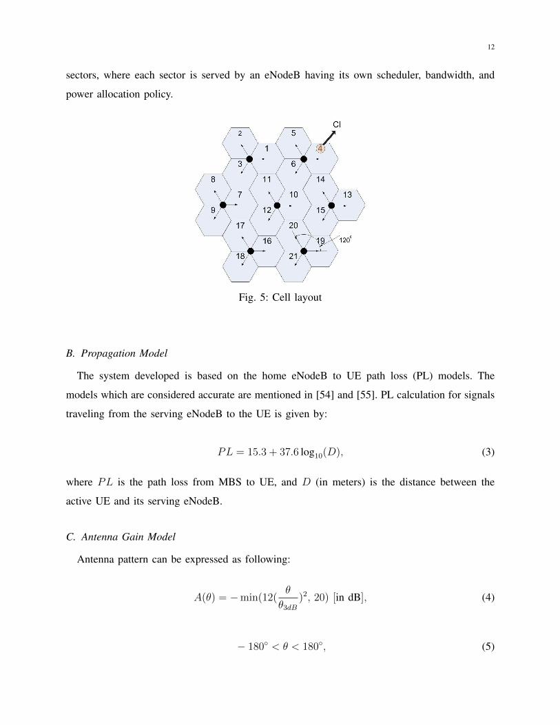
12
sectors, where each sector is served by an eNodeB having its own scheduler, bandwidth, and
power allocation policy.
Fig. 5: Cell layout
B. Propagation Model
The system developed is based on the home eNodeB to UE path loss (PL) models. The
models which are considered accurate are mentioned in [54] and [55]. PL calculation for signals
traveling from the serving eNodeB to the UE is given by:
PL = 15.3 + 37.6 log10(D), (3)
where PL is the path loss from MBS to UE, and D (in meters) is the distance between the
active UE and its serving eNodeB.
C. Antenna Gain Model
Antenna pattern can be expressed as following:
A(θ) = −min(12(θ
θ3dB)2, 20) [in dB], (4)
− 180◦ < θ < 180◦, (5)
13
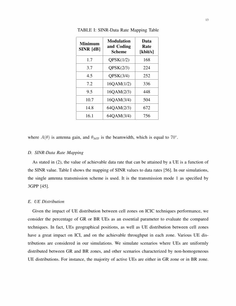
TABLE I: SINR-Data Rate Mapping Table
MinimumSINR [dB]
Modulationand Coding
Scheme
DataRate
[kbit/s]
1.7 QPSK(1/2) 168
3.7 QPSK(2/3) 224
4.5 QPSK(3/4) 252
7.2 16QAM(1/2) 336
9.5 16QAM(2/3) 448
10.7 16QAM(3/4) 504
14.8 64QAM(2/3) 672
16.1 64QAM(3/4) 756
where A(θ) is antenna gain, and θ3dB is the beamwidth, which is equal to 70◦.
D. SINR-Data Rate Mapping
As stated in (2), the value of achievable data rate that can be attained by a UE is a function of
the SINR value. Table I shows the mapping of SINR values to data rates [56]. In our simulations,
the single antenna transmission scheme is used. It is the transmission mode 1 as specified by
3GPP [45].
E. UE Distribution
Given the impact of UE distribution between cell zones on ICIC techniques performance, we
consider the percentage of GR or BR UEs as an essential parameter to evaluate the compared
techniques. In fact, UEs geographical positions, as well as UE distribution between cell zones
have a great impact on ICI, and on the achievable throughput in each zone. Various UE dis-
tributions are considered in our simulations. We simulate scenarios where UEs are uniformly
distributed between GR and BR zones, and other scenarios characterized by non-homogeneous
UE distributions. For instance, the majority of active UEs are either in GR zone or in BR zone.
14
IV. SIMULATION SCENARIOS
A. Simulation Environment
We use a MATLAB-based LTE downlink system level simulator [24, 25], developed by Vi-
enna University of Technology as the simulation platform. Frequency reuse-1 model and FFR
technique are included in the original version of the simulator. However, homogeneous power
allocation is only considered. We adjusted the power allocation scheme in order to allow allo-
cating different power levels to the available RBs. We have also integrated SFR technique and
reuse-3 model along with the existing FFR and reuse-1 schemes. Simulation parameters for the
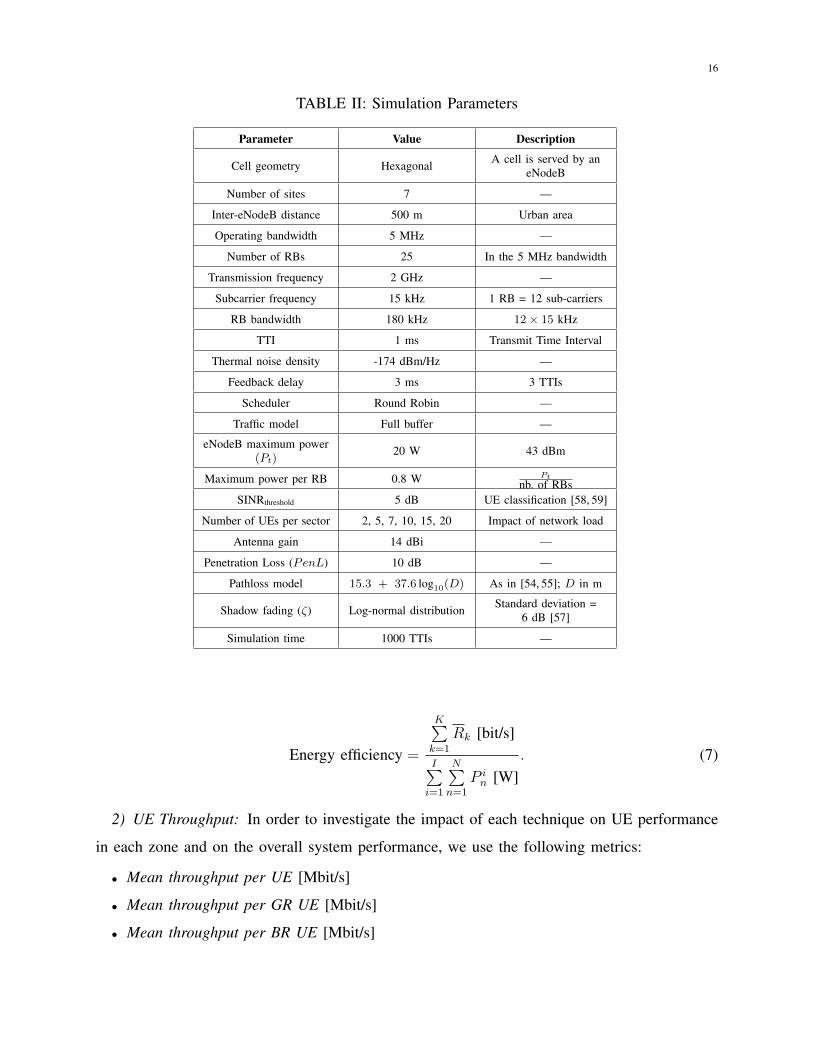
simulated LTE system [1, 57] and the ICIC techniques are summarized in Table II.
Cell geometry for our simulated LTE system is hexagonal, and each LTE site consists of three
adjacent hexagonal sectors, where each sector is served by an eNodeB. Inter-eNodeB distance
equals 500 m, which corresponds to an LTE network deployed in an urban area. In each cell,
25 RBs are available, since the operating bandwidth equals 5 MHz. However, traffic model
is full buffer i.e., all the available RBs are permanently allocated for the active UEs in the
network. UE scheduling is performed every one millisecond. Path loss model is the one defined
by 3GPP in [54, 55], and feedback reception at eNodeBs is delayed by three milliseconds. The
distribution of the shadow fading is log-normal. Its standard deviation equals 6 dB for urban
deployments, as specified by 3GPP technical specifications [57]. We note that when the shadow
fading increases, the useful signal power and the interfering signals power are both reduced. For
the frequency reuse-3 model, interference is null since each cell uses a disjoint portion of the
available spectrum. Thus, SINR is reduced since it is proportional to the useful signal power,
and UE throughput is reduced. For the frequency reuse-1 model, FFR, and SFR schemes, the
useful signal power and the interfering signals power are both reduced. Compared to the useful
signal power, the interfering signals power is more reduced since it is the sum of several signals
transmitted by the neighboring cells. Thus, SINR degradation is lower than that of the frequency
reuse-3 model. However, the relative comparison of these techniques when compared to each
other remains the same. When homogeneous power allocation is used, the maximum downlink
transmission power is allocated for each RB. However, SFR reduces the transmission power
allocated for RBs used by GR UEs. SINRthreshold is a predefined parameter, used to classify
active UEs into GR and BR UEs. It can be adjusted by mobile network operators according to
15
network load and UE satisfaction.
Unlike traditional works where the proposed interference mitigation technique is compared
to reuse-1 and reuse-m models under ordinary network conditions (e.g., homogeneous UE
density and uniform UE distribution), we investigate ICIC techniques under various simulation
scenarios. We study the impact of network load (number of UEs per eNodeB) and UE distribution
(percentage of GR UEs in the network) on system performance for each of the compared
techniques. For instance, we consider homogeneous UE density among all the cells, and we
start increasing the number of active UEs per cell. Therefore, we show the impact of network
load on UE satisfaction for reuse-1 model and other ICIC schemes. This study allows us to
choose the most adequate technique for each network load scenario e.g., system performance
is improved when using a specific ICIC technique when the network is highly loaded, whereas
reuse-1 offers a better performance for other scenarios. In addition, we consider not only uniform
UE distributions, but also scenarios where UEs are not uniformly distributed between cell-zones.
Thus, we study the impact of UE distribution on the chosen ICIC technique, and we show the
evolution of system performance when the percentage of GR UEs changes.
B. Performance Metrics
In order to compare the performance of the studied techniques, we define the following
performance comparison criteria:
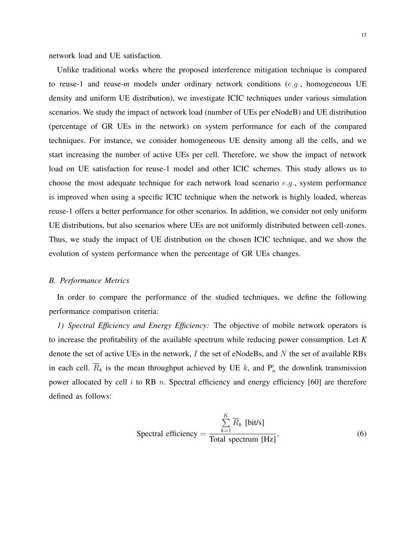
1) Spectral Efficiency and Energy Efficiency: The objective of mobile network operators is
to increase the profitability of the available spectrum while reducing power consumption. Let K
denote the set of active UEs in the network, I the set of eNodeBs, and N the set of available RBs
in each cell. Rk is the mean throughput achieved by UE k, and Pin the downlink transmission
power allocated by cell i to RB n. Spectral efficiency and energy efficiency [60] are therefore
defined as follows:
Spectral efficiency =
K∑k=1
Rk [bit/s]
Total spectrum [Hz], (6)
16
TABLE II: Simulation Parameters
Parameter Value Description
Cell geometry Hexagonal A cell is served by aneNodeB
Number of sites 7 —
Inter-eNodeB distance 500 m Urban area
Operating bandwidth 5 MHz —
Number of RBs 25 In the 5 MHz bandwidth
Transmission frequency 2 GHz —
Subcarrier frequency 15 kHz 1 RB = 12 sub-carriers
RB bandwidth 180 kHz 12× 15 kHz
TTI 1 ms Transmit Time Interval
Thermal noise density -174 dBm/Hz —
Feedback delay 3 ms 3 TTIs
Scheduler Round Robin —
Traffic model Full buffer —
eNodeB maximum power(Pt)
20 W 43 dBm
Maximum power per RB 0.8 W Pt
nb. of RBsSINRthreshold 5 dB UE classification [58, 59]
Number of UEs per sector 2, 5, 7, 10, 15, 20 Impact of network load
Antenna gain 14 dBi —
Penetration Loss (PenL) 10 dB —
Pathloss model 15.3 + 37.6 log10(D) As in [54, 55]; D in m
Shadow fading (ζ) Log-normal distribution Standard deviation =6 dB [57]
Simulation time 1000 TTIs —
Energy efficiency =
K∑k=1
Rk [bit/s]
I∑i=1
N∑n=1
P in [W]
. (7)
2) UE Throughput: In order to investigate the impact of each technique on UE performance
in each zone and on the overall system performance, we use the following metrics:
• Mean throughput per UE [Mbit/s]
• Mean throughput per GR UE [Mbit/s]
• Mean throughput per BR UE [Mbit/s]
17
For each simulation run, mean throughput is the average throughput achieved by UEs through-
out the simulation time. These three metrics give an overview about how the throughput of each
zone is modified when applying an ICIC technique. Thus, they allow to carry out a more detailed
performance comparison using significant throughput information.
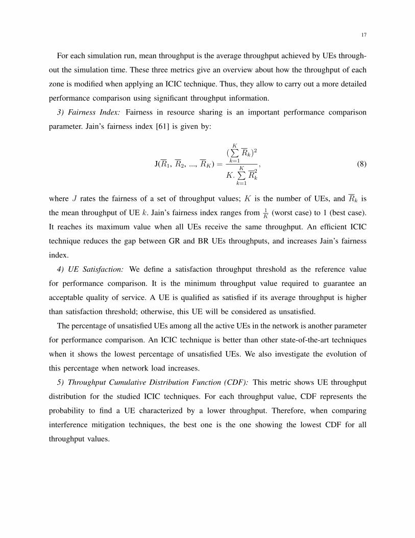
3) Fairness Index: Fairness in resource sharing is an important performance comparison
parameter. Jain’s fairness index [61] is given by:
J(R1, R2, ..., RK) =(
K∑k=1
Rk)2
K.K∑k=1
R2
k
, (8)
where J rates the fairness of a set of throughput values; K is the number of UEs, and Rk is
the mean throughput of UE k. Jain’s fairness index ranges from 1K
(worst case) to 1 (best case).
It reaches its maximum value when all UEs receive the same throughput. An efficient ICIC
technique reduces the gap between GR and BR UEs throughputs, and increases Jain’s fairness
index.
4) UE Satisfaction: We define a satisfaction throughput threshold as the reference value
for performance comparison. It is the minimum throughput value required to guarantee an
acceptable quality of service. A UE is qualified as satisfied if its average throughput is higher
than satisfaction threshold; otherwise, this UE will be considered as unsatisfied.
The percentage of unsatisfied UEs among all the active UEs in the network is another parameter
for performance comparison. An ICIC technique is better than other state-of-the-art techniques
when it shows the lowest percentage of unsatisfied UEs. We also investigate the evolution of
this percentage when network load increases.
5) Throughput Cumulative Distribution Function (CDF): This metric shows UE throughput
distribution for the studied ICIC techniques. For each throughput value, CDF represents the
probability to find a UE characterized by a lower throughput. Therefore, when comparing
interference mitigation techniques, the best one is the one showing the lowest CDF for all
throughput values.
18
V. SIMULATION RESULTS AND ANALYSIS
A. Spectral Efficiency versus Energy Efficiency
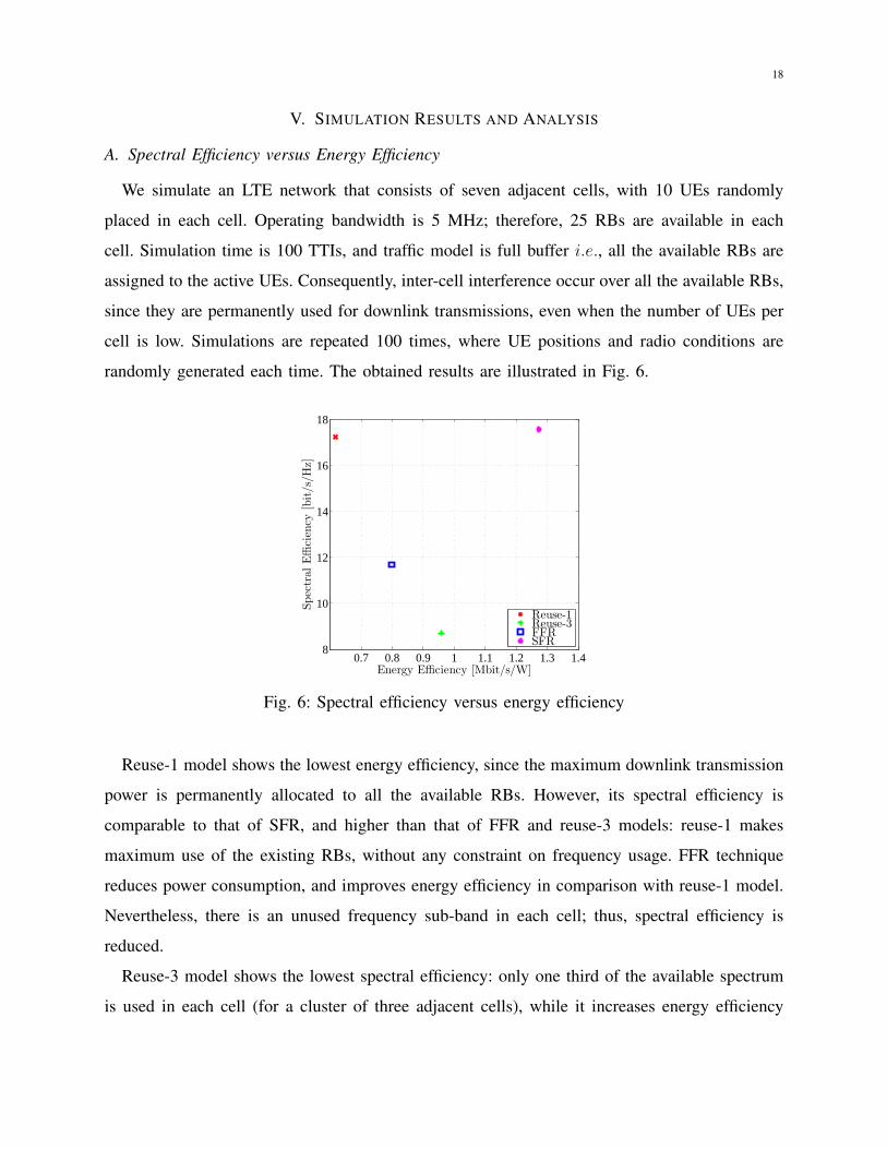
We simulate an LTE network that consists of seven adjacent cells, with 10 UEs randomly
placed in each cell. Operating bandwidth is 5 MHz; therefore, 25 RBs are available in each
cell. Simulation time is 100 TTIs, and traffic model is full buffer i.e., all the available RBs are
assigned to the active UEs. Consequently, inter-cell interference occur over all the available RBs,
since they are permanently used for downlink transmissions, even when the number of UEs per
cell is low. Simulations are repeated 100 times, where UE positions and radio conditions are
randomly generated each time. The obtained results are illustrated in Fig. 6.
0.7 0.8 0.9 1 1.1 1.2 1.3 1.48
10
12
14
16
18
Energy Efficiency [Mbit/s/W]
Spectral
Efficien
cy[bit/s/H
z]
Reuse-1Reuse-3FFRSFR
Fig. 6: Spectral efficiency versus energy efficiency
Reuse-1 model shows the lowest energy efficiency, since the maximum downlink transmission
power is permanently allocated to all the available RBs. However, its spectral efficiency is
comparable to that of SFR, and higher than that of FFR and reuse-3 models: reuse-1 makes
maximum use of the existing RBs, without any constraint on frequency usage. FFR technique
reduces power consumption, and improves energy efficiency in comparison with reuse-1 model.
Nevertheless, there is an unused frequency sub-band in each cell; thus, spectral efficiency is
reduced.
Reuse-3 model shows the lowest spectral efficiency: only one third of the available spectrum
is used in each cell (for a cluster of three adjacent cells), while it increases energy efficiency
19
in comparison with reuse-1 and FFR. SFR improves both spectral and energy efficiencies, in
comparison with dense frequency reuse model and other ICIC techniques. It uses a frequency
reuse factor of one with restrictions on power allocation; thus, it is able to improve energy
efficiency without sacrificing spectral efficiency.
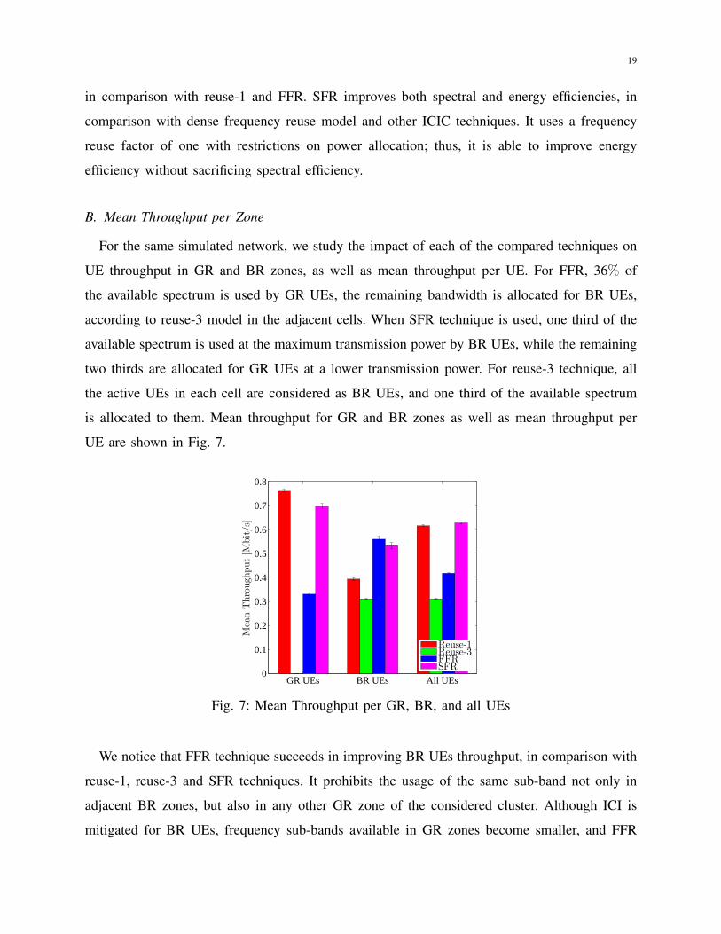
B. Mean Throughput per Zone
For the same simulated network, we study the impact of each of the compared techniques on
UE throughput in GR and BR zones, as well as mean throughput per UE. For FFR, 36% of
the available spectrum is used by GR UEs, the remaining bandwidth is allocated for BR UEs,
according to reuse-3 model in the adjacent cells. When SFR technique is used, one third of the
available spectrum is used at the maximum transmission power by BR UEs, while the remaining
two thirds are allocated for GR UEs at a lower transmission power. For reuse-3 technique, all
the active UEs in each cell are considered as BR UEs, and one third of the available spectrum
is allocated to them. Mean throughput for GR and BR zones as well as mean throughput per
UE are shown in Fig. 7.
GR UEs BR UEs All UEs0
0.1
0.2
0.3
0.4
0.5
0.6
0.7
0.8
MeanThrough
put[M
bit/s]
Reuse-1Reuse-3FFRSFR
Fig. 7: Mean Throughput per GR, BR, and all UEs
We notice that FFR technique succeeds in improving BR UEs throughput, in comparison with
reuse-1, reuse-3 and SFR techniques. It prohibits the usage of the same sub-band not only in
adjacent BR zones, but also in any other GR zone of the considered cluster. Although ICI is
mitigated for BR UEs, frequency sub-bands available in GR zones become smaller, and FFR

20
reduces the average throughput per UE when compared to reuse-1 model. Reuse-3 aggravates the
disadvantage of FFR, since only one third of the available spectrum is used by active UEs in each
cell. Thus, mean throughput per UE reaches its lowest value with reuse-3 model. SFR technique
improves BR UEs throughput without reducing mean throughput per UE for the entire network.
The power allocation strategy applied by SFR reduces ICI for BR UEs. Thus, it maximizes the
usage of the available spectrum in all network cells, and reduces ICI simultaneously.
C. Throughput Cumulative Distribution Function
We report throughput CDF for the compared techniques, under the same simulation scenario.
It allows us to study throughput distribution among active UEs in the network. CDF for reuse-1,
reuse-3, FFR, and SFR techniques is illustrated in Fig. 8.
0 0.5 1 1.5 2 2.5 30
0.2
0.4
0.6
0.8
1
Throughput [Mbit/s]
CDF Reuse-1
Reuse-3FFRSFR
Fig. 8: Throughput cumulative distribution function
For a given throughput value, CDF represents the probability to find a UE characterized
by a lower throughput. The lower the CDF is, the better the quality of service is. We notice
that throughput CDF of reuse-3 model is the first to reach the maximum. In other words, the
probability to find a UE served with a throughput less than 1 Mbit/s equals one. FFR improves
throughput CDF function in comparison with reuse-3. However, it reaches the maximum before
reuse-1 CDF. When using SFR, the number of UEs suffering of bad quality of service is reduced.
For relatively low throughput values (less than 1 Mbit/s) throughput CDF for SFR is the lowest
curve; thus, it shows the lowest percentage of UEs served with low throughputs. Moreover, SFR
curve is the last one to reach its maximum (at 3 Mbit/s approximately). Consequently, when

21
mobile network operators seek to improve throughput CDF for the entire system, SFR is the most
adequate technique among the compared ICIC schemes. It succeeds in reducing the percentage of
UEs with relatively low throughputs, while also improving the maximum achievable throughput
in the network. Through restrictions made on downlink transmission power allocation, SFR
reduces ICI for BR UEs, and provides enough bandwidth for GR UEs to achieve higher data
rates.
D. UE Satisfaction versus Network Load
In this paragraph, we compare the percentage of unsatisfied UEs for each technique. The
simulated network consists of seven adjacent hexagonal LTE cells. We simulate several scenarios,
where the number of UEs per cell is increased. For each scenario, simulations are repeated
100 times, and the obtained results are illustrated in Fig. 9. Satisfaction throughput threshold is
set to 512 kbit/s. We assume that the average throughput per UE is required to be higher than
512 kbit/s in order to fulfill its downlink data traffic demands. If the average throughput of a
UE is higher than this threshold, it is considered as satisfied; otherwise, this UE is considered
as an unsatisfied UE.
0 5 10 15 200
20
40
60
80
100
Nb of UEs per eNodeB
%ofunsatisfied
UEs
Reuse-1Reuse-3FFRSFR
Fig. 9: UE satisfaction versus network load
We notice that reuse-3 model shows the lowest percentage of unsatisfied UEs for low network
loads. When each cell is using a disjoint part of spectrum, ICI problems are largely eliminated.
However, the percentage of unsatisfied UEs becomes the highest among all the compared

22
techniques when the network load increases. Only one third of the available spectrum is used in
each cell; thus, network capacity and UE satisfaction are reduced when network load increases.
Despite of the power reduction over RBs allocated for GR UEs, SFR shows approximately
the same percentage of unsatisfied UEs as for reuse-1 model. The power allocation strategy
reduces ICI, especially for BR UEs, and GR throughput loss is compensated. Compared to
reuse-1 model, FFR increases the percentage of unsatisfied UEs, due to restrictions on RB usage
between network cells. A portion of the available spectrum is not allowed to be used in each
cell. When network load increases, FFR performance becomes better than that of reuse-3 model.
It is a compromise between reuse-1 model and reuse-3 model. In fact, when using FFR, we
guarantee that BR UEs of adjacent cells operate on disjoint spectrum. Thus, it makes use of
the main advantage of reuse-3 model: ICI is mitigated for BR UEs. Moreover, it avoids the
disadvantage of reuse-3 model i.e., the lack of RBs available in each cell, by allowing the usage
of reuse-1 model in GR zones of the neighboring cells.
E. UE Satisfaction versus UE Distribution
The particularity of our work is that we compare the performance of different ICIC techniques
under both homogeneous and non-homogeneous UE distributions. When UEs are homogeneously
distributed between cell zones, the percentage of GR UEs is close to or equals 50%. In other
words, half of the active UEs are GR UEs, while the other half are BR UEs. However, when
non-homogeneous UE distributions are considered, the majority of active UEs are either in GR
zone (when the percentage of GR UEs is greater than the percentage of BR UEs), or in BR zone
(when the percentage of BR UEs is greater than the percentage of GR UEs). In this paragraph,
we consider seven adjacent cells with 10 UEs in each cell. UE positions are generated in a
manner that the percentage of GR UEs varies between 20% and 80%. For each UE distribution
(percentage of GR UEs), simulations are repeated 100 times, and the obtained results are reported
in Fig. 10.
According to these results, FFR reduces the percentage of unsatisfied UEs in the network
when their distribution is approximately homogeneous between BR and GR zones. It improves
system performance in comparison with reuse-1 model when 50% to 70% of active UEs are GR
UEs. However, when the majority of active UEs are either in the BR zone, or in the GR zone, the
percentage of unsatisfied UEs exceeds that of reuse-1 model. FFR is a static technique, and RB

23
20 30 40 50 60 70 800
10
20
30
40
50
60
% of GR UEs
%ofunsatisfiedUEs
Reuse-1Reuse-3FFRSFR
Fig. 10: UE satisfaction versus percentage of GR UEs
distribution among GR and BR zones is not dynamically adjusted according to UE distribution.
The same static aspect appears with SFR, where UE satisfaction is not better than reuse-1 when
the majority of UEs are BR UEs. However, SFR reduces the percentage of unsatisfied UEs
when more than 50% of active UEs are GR UEs. Reuse-3 technique increases the percentage
of unsatisfied UEs when compared to reuse-1 model, for all UE distributions. Restrictions made
on RB usage in each cell reduces spectrum profitability, which in turn has a negative impact on
the achievable throughput.
We also conclude that static configuration parameters for FFR and SFR can be adjusted to meet
UE distribution between BR and GR zones. The choice of these tuning parameters [30, 35] is
made by mobile network operators according to quality of service requirements and deployment
scenarios.
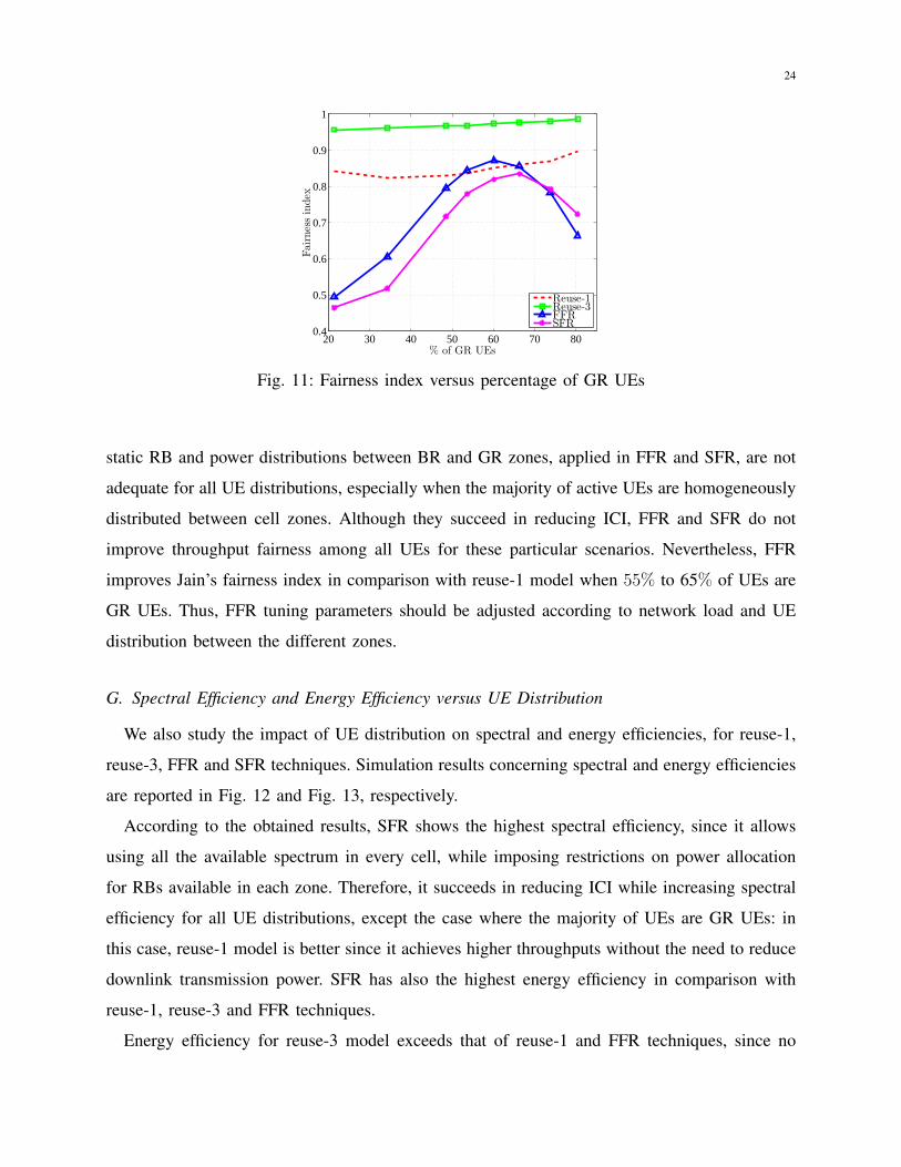
F. Fairness Index versus UE Distribution
For the same simulation scenario, we study UEs throughput fairness index when the percentage
of GR UEs in the network changes. For each UE distribution, simulations are repeated 100 times,
and the obtained results are shown in Fig. 11.
Reuse-3 model shows permanently the highest throughput fairness index among all the studied
techniques. It exceeds Jain’s fairness index of reuse-1 model, where BR UEs suffer from ICI,
which has a negative impact on their throughput, while GR UEs achieve higher throughputs. The
24
20 30 40 50 60 70 800.4
0.5
0.6
0.7
0.8
0.9
1
% of GR UEs
Fairness
index
Reuse-1Reuse-3FFRSFR
Fig. 11: Fairness index versus percentage of GR UEs
static RB and power distributions between BR and GR zones, applied in FFR and SFR, are not
adequate for all UE distributions, especially when the majority of active UEs are homogeneously
distributed between cell zones. Although they succeed in reducing ICI, FFR and SFR do not
improve throughput fairness among all UEs for these particular scenarios. Nevertheless, FFR
improves Jain’s fairness index in comparison with reuse-1 model when 55% to 65% of UEs are
GR UEs. Thus, FFR tuning parameters should be adjusted according to network load and UE
distribution between the different zones.
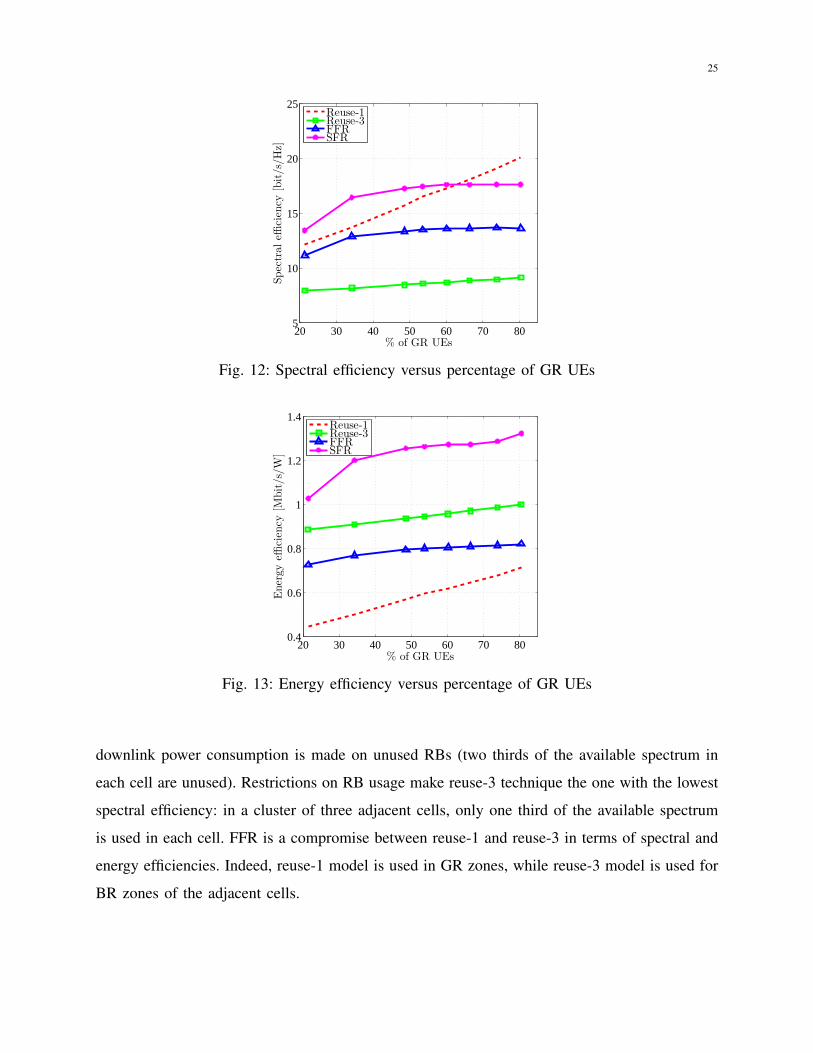
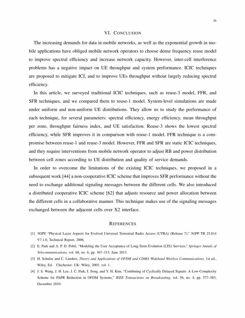
G. Spectral Efficiency and Energy Efficiency versus UE Distribution
We also study the impact of UE distribution on spectral and energy efficiencies, for reuse-1,
reuse-3, FFR and SFR techniques. Simulation results concerning spectral and energy efficiencies
are reported in Fig. 12 and Fig. 13, respectively.
According to the obtained results, SFR shows the highest spectral efficiency, since it allows
using all the available spectrum in every cell, while imposing restrictions on power allocation
for RBs available in each zone. Therefore, it succeeds in reducing ICI while increasing spectral
efficiency for all UE distributions, except the case where the majority of UEs are GR UEs: in
this case, reuse-1 model is better since it achieves higher throughputs without the need to reduce
downlink transmission power. SFR has also the highest energy efficiency in comparison with
reuse-1, reuse-3 and FFR techniques.
Energy efficiency for reuse-3 model exceeds that of reuse-1 and FFR techniques, since no
25
20 30 40 50 60 70 805
10
15
20
25
% of GR UEs
Spectraleffi
ciency
[bit/s/Hz]
Reuse-1Reuse-3FFRSFR
Fig. 12: Spectral efficiency versus percentage of GR UEs
20 30 40 50 60 70 800.4
0.6
0.8
1
1.2
1.4
% of GR UEs
Energyeffi
ciency
[Mbit/s/W
]
Reuse-1Reuse-3FFRSFR
Fig. 13: Energy efficiency versus percentage of GR UEs
downlink power consumption is made on unused RBs (two thirds of the available spectrum in
each cell are unused). Restrictions on RB usage make reuse-3 technique the one with the lowest
spectral efficiency: in a cluster of three adjacent cells, only one third of the available spectrum
is used in each cell. FFR is a compromise between reuse-1 and reuse-3 in terms of spectral and
energy efficiencies. Indeed, reuse-1 model is used in GR zones, while reuse-3 model is used for
BR zones of the adjacent cells.
26
VI. CONCLUSION
The increasing demands for data in mobile networks, as well as the exponential growth in mo-
bile applications have obliged mobile network operators to choose dense frequency reuse model
to improve spectral efficiency and increase network capacity. However, inter-cell interference
problems has a negative impact on UE throughput and system performance. ICIC techniques
are proposed to mitigate ICI, and to improve UEs throughput without largely reducing spectral
efficiency.
In this article, we surveyed traditional ICIC techniques, such as reuse-3 model, FFR, and
SFR techniques, and we compared them to reuse-1 model. System-level simulations are made
under uniform and non-uniform UE distributions. They allow us to study the performance of
each technique, for several parameters: spectral efficiency, energy efficiency, mean throughput
per zone, throughput fairness index, and UE satisfaction. Reuse-3 shows the lowest spectral
efficiency, while SFR improves it in comparison with reuse-1 model. FFR technique is a com-
promise between reuse-1 and reuse-3 model. However, FFR and SFR are static ICIC techniques,
and they require interventions from mobile network operator to adjust RB and power distribution
between cell zones according to UE distribution and quality of service demands.
In order to overcome the limitations of the existing ICIC techniques, we proposed in a
subsequent work [44] a non-cooperative ICIC scheme that improves SFR performance without the
need to exchange additional signaling messages between the different cells. We also introduced
a distributed cooperative ICIC scheme [62] that adjusts resource and power allocation between
the different cells in a collaborative manner. This technique makes use of the signaling messages
exchanged between the adjacent cells over X2 interface.
REFERENCES
[1] 3GPP, “Physical Layer Aspects for Evolved Universal Terrestrial Radio Access (UTRA) (Release 7),” 3GPP TR 25.814
V7.1.0, Technical Report, 2006.
[2] E. Park and A. P. D. Pobil, “Modeling the User Acceptance of Long-Term Evolution (LTE) Services,” Springer Annals of
Telecommunications, vol. 68, no. 6, pp. 307–315, June 2013.
[3] H. Schulze and C. Lueders, Theory and Applications of OFDM and CDMA Wideband Wireless Communications, 1st ed.,
Wiley, Ed. Chichester: UK: Wiley, 2005, vol. 1.
[4] J. S. Wang, J. H. Lee, J. C. Park, I. Song, and Y. H. Kim, “Combining of Cyclically Delayed Signals: A Low-Complexity
Scheme for PAPR Reduction in OFDM Systems,” IEEE Transactions on Broadcasting, vol. 56, no. 4, pp. 577–583,
December 2010.
27
[5] Y. Wang, X. Yang, A. Ma, and L. Cuthbert, “Intelligent Resource Optimisation Using Semi-Smart Antennas in LTE
OFDMA Systems,” in 2009 IEEE International Conference on Communications Technology and Applications, October
2009, pp. 173–179.
[6] D. Xiao, X. Yu, and D. Yang, “A Novel Downlink ICIC Method Based on User Position in LTE-Advanced Systems,” in
2012 IEEE Vehicular Technology Conference (VTC Fall), September 2012, pp. 1–5.
[7] J. Denes and A. Keedwell, “Frequency Allocation for a Mobile Radio Telephone System,” IEEE Transactions on
Communications, vol. 36, no. 6, pp. 765–767, June 1988.
[8] V. Donald, “Advanced Mobile Phone Service: The Cellular Concept,” The Bell System Technical Journal, vol. 58, no. 1,
pp. 15–41, January 1979.
[9] D. L. J. P. Javaudin, J. Laine and O. Seller, “On Inter-Cell Interference in OFDMA Wireless Systems,” in Proc. European
Signal Processing Conf., Antalya, 2005.
[10] I. T. S. Sesia and M. Baker, LTE - The UMTS Long Term Evolution from Theory to Practice, 1st ed., Wiley, Ed. Chichester:
Wiley, 2009.
[11] G. Ku and J. Walsh, “Resource Allocation and Link Adaptation in LTE and LTE Advanced: A Tutorial,” IEEE
Communications Surveys Tutorials, vol. PP, no. 99, pp. 1–1, December 2014.
[12] A. Daeinabi, K. Sandrasegaran, and X. Zhu, “Survey of Intercell Interference Mitigation Techniques in LTE Downlink
Networks,” in 2012 Australasian Telecommunication Networks and Applications Conference, November 2012, pp. 1–6.
[13] M. Sternad, T. Ottosson, A. Ahlen, and A. Svensson, “Attaining both Coverage and High Spectral Efficiency with Adaptive
OFDM Downlinks,” in IEEE 58th Vehicular Technology Conference, vol. 4, October 2003, pp. 2486–2490.
[14] Huawei, “Soft Frequency Reuse Scheme for UTRANLTE (R1-050507),” 3GPP RAN WG1 no. 41, Athens, Greece,
Technical report, May 2005.
[15] C. Kosta, B. Hunt, A. U. Quddus, and R. Tafazolli, “An Improved Inter-cell Interference Coordination (ICIC) for OFDMA
Multi-Cell Systems,” in Proceedings of the 19th European Wireless Conference, April 2013, pp. 1–5.
[16] M. Dirani and Z. Altman, “A cooperative Reinforcement Learning approach for Inter-Cell Interference Coordination in
OFDMA Cellular Networks,” in Proceedings of the 8th International Symposium on Modeling and Optimization in Mobile,
Ad Hoc and Wireless Networks, Avignon, May 2010, pp. 170–176.
[17] D. Lee, H. Seo, B. Clerckx, E. Hardouin, D. Mazzarese, S. Nagata, and K. Sayana, “Coordinated Multipoint Transmission
and Reception in LTE-Advanced: Deployment Scenarios and Operational Challenges,” IEEE Communications Magazine,
vol. 50, no. 2, pp. 148–155, February 2012.
[18] S. Das, H. Viswanathan, and G. Rittenhouse, “Dynamic Load Balancing Through Coordinated Scheduling in Packet Data
Systems,” in INFOCOM 2003. Twenty-Second Annual Joint Conference of the IEEE Computer and Communications. IEEE
Societies, vol. 1, March 2003, pp. 786–796.
[19] N. Saquib, E. Hossain, L. B. Le, and D. I. Kim, “Interference Management in OFDMA Femtocell Networks: Issues and
Approaches,” IEEE Wireless Communications, vol. 19, no. 3, pp. 86–95, June 2012.
[20] S. Xu, J. Han, and T. Chen, “Enhanced Inter-Cell Interference Coordination in Heterogeneous Networks for LTE-Advanced,”
in IEEE 75th Vehicular Technology Conference (VTC Spring), Yokohama, May 2012, pp. 1–5.
[21] G. Fodor, C. Koutsimanis, A. Rcz, N. Reider, A. Simonsson, and W. Mller, “Intercell Interference Coordination in OFDMA
Networks and in the 3GPP Long Term Evolution System,” Journal of Communications, vol. 4, pp. 445–453, 2009.
[22] A. Hamza, S. Khalifa, H. Hamza, and K. Elsayed, “A Survey on Inter-Cell Interference Coordination Techniques in
OFDMA-Based Cellular Networks,” IEEE Communications Surveys Tutorials, vol. 15, no. 4, pp. 1642–1670, 2013.
28
[23] Y. L. Lee, T. C. Chuah, J. Loo, and A. Vinel, “Recent Advances in Radio Resource Management for Heterogeneous
LTE/LTE-A Networks,” IEEE Communications Surveys Tutorials, vol. 16, no. 4, pp. 2142–2180, 2014.
[24] VUT. (2014) LTE Downlink System Level Simulator, Vienna University of Technology. Vienna University of Technology.
[Online]. Available: http://www.nt.tuwien.ac.at
[25] J. Ikuno, M. Wrulich, and M. Rupp, “System Level Simulation of LTE Networks,” in IEEE 71st Vehicular Technology
Conference, Taipei, May 2010, pp. 1–5.
[26] A. De Pasquale, N. Magnani, and P. Zanini, “Optimizing Frequency Planning in the GSM System,” in IEEE 1998
International Conference on Universal Personal Communications, vol. 1, Florence, October 1998, pp. 293–297.
[27] F. Delli Priscoli, N. Magnani, V. Palestini, and F. Sestini, “Application of Dynamic Channel Allocation Strategies to the
GSM Cellular Network,” IEEE Journal on Selected Areas in Communications, vol. 15, no. 8, pp. 1558–1567, October
1997.
[28] S. Engstrom, T. Johansson, F. Kronestedt, M. Larsson, S. Lidbrink, and H. Olofsson, “Multiple Reuse Patterns for Frequency
Planning in GSM Networks,” in IEEE 48th Vehicular Technology Conference, vol. 3, Ottawa, May 1998, pp. 2004–2008.
[29] P. Frank, A. Muller, H. Droste, and J. Speidel, “Cooperative Interference-Aware Joint Scheduling for the 3GPP LTE Uplink,”
in IEEE 21st International Symposium on Personal Indoor and Mobile Radio Communications, Istanbul, September 2010,
pp. 2216–2221.
[30] N. Hassan and M. Assaad, “Optimal Fractional Frequency Reuse (FFR) and Resource Allocation in Multiuser OFDMA
System,” in 2009 International Conference on Information and Communication Technologies, Karachi, August 2009, pp.
88–92.
[31] Z. Qin, Z. Zhong, R. Xu, and G. Bai, “System Performance of Soft Frequency Reuse in LTE Railway Networks,” in IEEE
11th International Conference on Signal Processing, vol. 2, Beijing, October 2012, pp. 1566–1570.
[32] C. Jiming, W. Peng, and Z. Jie, “Adaptive Soft Frequency Reuse Scheme for in-Building Dense Femtocell Networks,”
China Communications, vol. 10, no. 1, pp. 44–55, January 2013.
[33] M. Y. W. Raafat and I. Tarrad, “Comprehensive Survey on Various ICIC Schemes and Proposed 3G RF Interference
Mitigation Techniques for OFDM Downlink on Cellular Networks,” J. Engineering and Architecture, vol. 1, no. 2, December
2013.
[34] C. Kosta, B. Hunt, A. Quddus, and R. Tafazolli, “On Interference Avoidance Through Inter-Cell Interference Coordination
(ICIC) Based on OFDMA Mobile Systems,” IEEE Communications Surveys Tutorials, vol. 15, no. 3, pp. 973–995,
December 2013.
[35] M. Assaad, “Optimal Fractional Frequency Reuse (FFR) in Multicellular OFDMA System,” in IEEE 68th Vehicular
Technology Conference, Calgary, September 2008, pp. 1–5.
[36] M. Yassin, S. Lahoud, M. Ibrahim, and K. Khawam, “A Downlink Power Control Heuristic Algorithm for LTE Networks,”
in 21st International Conference on Telecommunications, Lisbon, May 2014, pp. 323–327.
[37] M. Aboul Hassan, E. Sourour, and S. Shaaban, “Novel Resource Allocation Algorithm for Improving Reuse One Scheme
Performance in LTE Networks,” in 21st International Conference on Telecommunications, Lisbon, May 2014, pp. 166–170.
[38] D. Niyato and E. Hossain, “A Cooperative Game Framework for Bandwidth Allocation in 4G Heterogeneous Wireless
Networks,” in 2006 IEEE International Conference on Communications, vol. 9, June 2006, pp. 4357–4362.
[39] J. Zheng, Y. Cai, and A. Anpalagan, “A Stochastic Game-Theoretic Approach for Interference Mitigation in Small Cell
Networks,” IEEE Communications Letters, vol. 19, no. 2, pp. 251–254, February 2015.
[40] M. Rahman and H. Yanikomeroglu, “Enhancing Cell-Edge Performance: A Downlink Dynamic Interference Avoidance
29
Scheme with Inter-Cell Coordination,” IEEE Transactions on Wireless Communications, vol. 9, no. 4, pp. 1414–1425,
April 2010.
[41] M. Necker, “Scheduling Constraints and Interference Graph Properties for Graph-based Interference Coordination in
Cellular OFDMA Networks,” Springer J. Mobile Networks and Applications, vol. 14, no. 4, pp. 539–550, January 2009.
[42] R. Chang, Z. Tao, J. Zhang, and C.-C. Kuo, “Multicell OFDMA Downlink Resource Allocation Using a Graphic
Framework,” IEEE Transactions on Vehicular Technology, vol. 58, no. 7, pp. 3494–3507, September 2009.
[43] B. Krasniqi, M. Wrulich, and C. Mecklenbrauker, “Network-Load Dependent Partial Frequency Reuse for LTE,” in 9th
International Symposium on Communications and Information Technology, Icheon, September 2009, pp. 672–676.
[44] M. Yassin, S. Lahoud, M. Ibrahim, K. Khawam, D. Mezher, and B. Cousin, “Non-Cooperative Inter-Cell Interference
Coordination Technique for Increasing Through Fairness in LTE Networks,” in IEEE 81st Vehicular Technology Conf,
Glasgow, May 2015.
[45] 3GPP, “Evolved Universal Terrestrial Radio Access (E-UTRA): Physical Layer Procedures,” 3GPP TS 36.213 V11.11.0,
Technical Specification, December 2013.
[46] E. Hossain, M. Rasti, H. Tabassum, and A. Abdelnasser, “Evolution Toward 5G Multi-Tier Cellular Wireless Networks:
An Interference Management Perspective,” IEEE Wireless Communications, vol. 21, no. 3, pp. 118–127, June 2014.
[47] Z. A. Shamsan, T. A. Rahman, and A. M. AlHetar, “Interference Coordination for LTE-Advanced and FM Broadcasting
Interoperability,” Springer Annals of Telecommunications, vol. 67, no. 10, pp. 477–483, October 2012.
[48] M. Sawahashi, Y. Kishiyama, A. Morimoto, D. Nishikawa, and M. Tanno, “Coordinated Multipoint Transmission/Reception
Techniques for LTE-Advanced [Coordinated and Distributed MIMO],” IEEE Wireless Communications, vol. 17, no. 3, pp.
26–34, June 2010.
[49] Y. S. T. Tran and O. Shin, “Overview of Enabling Technologies for 3GPP LTE-Advanced,” EURASIP J. Wireless
Communications and Networking, vol. 2012, no. 2, February 2012.
[50] N. Saquib, E. Hossain, and D. I. Kim, “Fractional Frequency Reuse for Interference Management in LTE-Advanced
HetNets,” IEEE Wireless Communications, vol. 20, no. 2, pp. 113–122, April 2013.
[51] H. Dahrouj and W. Yu, “Coordinated Beamforming for the Multicell Multi-Antenna Wireless System,” IEEE Transactions
on Wireless Communications, vol. 9, no. 5, pp. 1748–1759, May 2010.
[52] S. Deb, P. Monogioudis, J. Miernik, and J. Seymour, “Algorithms for Enhanced Inter-Cell Interference Coordination (eICIC)
in LTE HetNets,” IEEE/ACM Transactions on Networking, vol. 22, no. 1, pp. 137–150, February 2014.
[53] N. Zia, S. Mwanje, and A. Mitschele-Thiel, “A Policy Based Conflict Resolution Mechanism for MLB and MRO in LTE
Self-Optimizing Networks,” in 2014 IEEE Symposium on Computers and Communication, Funchal, June 2014, pp. 1–6.
[54] 3GPP, “Radio Frequency (RF) System Scenarios,” 3GPP TR 36.931 Release 9, Technical Report, 2006.
[55] 3GPP, “Radio Frequency (RF) System Scenarios,” 3GPP TR 36.922, Technical Report, June 2006.
[56] H. Ramli, R. Basukala, K. Sandrasegaran, and R. Patachaianand, “Performance of Well Known Packet Scheduling
Algorithms in the Downlink 3GPP LTE System,” in IEEE 9th Malaysia International Conference on Communications,
Kuala Lumpur, December 2009, pp. 815–820.
[57] 3GPP, “Evolved Universal Terrestrial Radio Access (E-UTRA): Further Advancements for E-UTRA Physical Layer Aspects
(Release 9),” 3GPP TR 36.814 V9.0.0, Technical Report, March 2010.
[58] M. T. Kawser, N. I. B. Hamid, M. N. Hasan, M. S. Alam, and M. M. Rahman., “Downlink SNR to CQI Mapping for
Different Multiple Antenna Techniques in LTE,” International Journal of Information and Electronics Engineering, vol. 2,
no. 5, pp. 756–760, September 2012.
30
[59] Fujitsu Network Communications Inc., “Enhancing LTE Cell-Edge Performance via PDCCH ICIC,” White Paper, Fujitsu,
2011.
[60] M. Sarkiss and M. Kamoun, “On the Energy Efficiency of Base Station Cooperation under Limited Backhaul Capacity,”
Springer Annals of Telecommunications, vol. 69, no. 10, pp. 539–551, October 2014.
[61] R. K. Jain, D. W. Chiu, and W. R. Hawe, “A Quantitative Measure of Fairness and Discrimination for Resource Allocation
and Shared Computer System,” Digital Equipment Corporation, Technical Report, September 1984.
[62] M. Yassin, Y. Dirani, M. Ibrahim, S. Lahoud, D. Mezher, and B. Cousin, “A Novel Dynamic Inter-Cell Interference
Coordination Technique for LTE Networks,” in IEEE 26th Annual Int. Symp. Personal, Indoor, and Mobile Radio
Communications, Hong Kong, 2015.