1 Solid State Storage (SSS) System Error Recovery LHO 08 For NASA Langley Research Center.
25
1 Solid State Storage (SSS) System Error Recovery LHO 08 For NASA Langley Research Center
-
Upload
donald-eaton -
Category
Documents
-
view
214 -
download
1
Transcript of 1 Solid State Storage (SSS) System Error Recovery LHO 08 For NASA Langley Research Center.

1
Solid State Storage (SSS) System Error Recovery
LHO 08
For NASA Langley Research Center
2
Background• NASA Langley Research Center is building a system to record
streaming video and other data when the Space Shuttle docks with the Space Station.
• This data will be used to develop algorithms that will enable the next generation of the space station to perform autonomous docking.
• Due to the harsh environment in space the data will be stored in a RAID array of solid state SATA drives with the capability of recovering data even if two drives fail.
• This Solid State Storage (SSS) system is being developed at VCU.
• We will look at the that portion of the system that deals with drive error recovery.

3
Proposed SSS system OverviewRAID Controller Board
FPGARaid Controller
UnSwitched +3.3V DC From PDU
UnSwitched +5V DC From PDU
Flash Drive #1 Flash Drive #2 Flash Drive #N-1 Flash Drive #N...
SATA SATA SATA SATA...
SATA SATA SATA SATA
Aurora Serial interface Read/Write
To data recorder

4
SSS Data Recovery• The Solid State Storage (SSS) system will consist
of six solid state data drives. The discussion will be directed to this specific configuration.
• The data will be sector striped across these six drives.
• A modified RAID 6 system capable of recovering data from two corrupted sectors in a stripe is proposed.– Optimized for long single-thread transfers that are
multiples of the entire stripe.

5
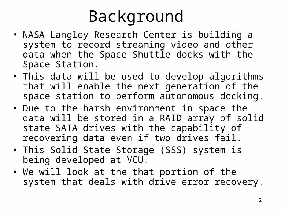
RAID 5• To illustrate concepts and implications
consider a RAID 5 implementation.• RAID 5 uses striped array with rotating
parity. • Optimized for short, multithreaded
transfers.• Capable of recovering from a single drive
failure.
6
RAID 5 system consisting of three data drives and rotating parity.
Four stripes for sectors A, B, C, and D are shown.

7
Rotating Parity• Why rotating parity?• The following steps are necessary to update a single data sector in a
stripe.– The old data sector and the parity sector for the stripe must be read.– Compute the new parity using the new data sector, old data sector, and old
parity.– Write new data sector and new parity sector.
• Thus, to write to a data sector both the data sector and parity sector must be read and written.
• Since there are many data drives a fixed parity drive would accessed much more frequently than a data drive.
• This excessive access of a single parity drive is avoid by rotating parity across all drives.

8
Rotating parity not needed in SSS• The SSS is required to store long data streams. Not
random sectors.• Make the size of these streams a multiple of the stripe size.• An entire stripe with parity will be buffered.• The entire stripe with party will be simultaneously written
to all drives.– It is not necessary to first read the drives.
• The SSS will always read and write entire stripes.– Easier to implement.– Faster access.

9
ParityParity encoding is given by
Where Di represent a data byte in a sector on drive i.
If both sides of the above equation are exclusive ored with P, then
D5 for example can be recovered by
0 1 2 3 4 5P D D D D D D
0 1 2 3 4 5
0 1 2 3 4 5
0 1 2 3 4 50
P D D D D D D
P P D D D D D D P
D D D D D D P
5 0 1 2 3 4D D D D D D P

10
Parity problem• Using parity it is easy to recover data on a single
drive if we know that drive is bad.• We may have data corruption on a drive without
without the entire drive failing. – Undetectable based on parity alone.
• Propose to include a 32-bit CRC in sector.– Simple to implement.– Less than 1% overhead.– In RAID 6 will ensure as long as a stripe has no more than
two bad sectors the data in that stripe can be recovered.

11
Key Conclusions
• Write data as entire stripes.
• Used fixed parity drive.
• Include sector CRC.

12
Raid 6 (modified)
• Use two fixed parity drives (P and Q).
• Data can be recovered if two sectors in a stripe are corrupted.
• P parity is the same as RAID 5 (simple XOR).– Easy to encode and easy to recover data.
• Q parity is more complicated.

13
Q parity encoding0 1 2 3 4 5P D D D D D D
The Q parity is a Reed-Solomon code given by 0 0 1 1 2 2 3 3 4 4 5 5Q g D g D g D g D g D g D
0 1 2 3 4 51 2 4 8 16 32Q D D D D D D
Where is Galois Field (GF) multiplication and gi is a
constant. For i < 8 it turns out that gi = 2i. For larger i, it not
as simple. For example g8 = 29.
But for the SSS application Q simplifies to
The problem is how to compute the GF multiplication.

14
GF multiplication• In ordinary arithmetic multiplication can be
accomplished summing the logs and taking the inverse log.
• GF multiplication is typically accomplished using lookup tables to find the GF log and inverse log. The addition in modulo 255.
See Xilinx application note XAPP731 “Hardware Accelerator for RADD 6 Parity Generation / Data Recovery Controller”.
1255log log ( ) log ( )GF GF GFA B A B

15

16

17
Examples
1255
1255
1
1
0 03 0 05 log log (0 03) log (0 05)
log 0 19 0 32
log 0 4 mod 0
log 0 4 0 0
GF GF GF
GF
GF
GF
x x x x
x x
x B xFF
x B x F
1255
1255
1
1
0 07 0 05 log log (0 07) log (0 05)
log 0 6 0 32
log 0 8 mod 0
log 0 8 0 1
GF GF GF
GF
GF
GF
x x x x
xC x
xF xFF
xF x B

18
Examples
1255
1255
1
1
0 12 0 05 log log (0 12) log (0 05)
log 0 0 0 32
log 0 112 mod 0
log 0 13 0 5
GF GF GF
GF
GF
GF
x x x x
xE x
x xFF
x x A
Note: AB = 0 if A = 0 or B = 0. This is a special case and cannot be computed using logs.
It is also worth noting that A1 = A. This does follow from using logs since logGF(0x01) = 0.

19
Elaboration on Galois Field Mathematics• Évariste Galois (1832)
– Established many of the ideas of group theory.– Left only sixty pages of mathematical writings.– Mortally wounded in a duel at age 20.
• Most of his major centrifugations stem from a letter written the night before the duel.
• His work has had great impact.• Provides powerful tool for investigating fundamental mathematical
problems.– Roots of algebraic equations.– GF theory provides simple proof that an angle cannot be trisected using only
compass and unmarked straightedge.» This had baffled mathematicians since the time of Euclid.
• Recently applied to computer design and data-communication systems.

20
Galois Field Mathematics
• A Galois Field is a algebraic structure <G,,> where G is a set consisting of 2n elements, is addition mod 2 (bit wise XOR) and is GF multiplication. Math similar to ordinary arithmetic.
and is commutative and associative.• Distributive such that • We are only concerned with GF(28) where the set G
has 256 elements. We will use a hex byte to specify the elements.
• Then A A = 0x00, A 0x00 = 0x00, A 0x01 = A
( ) ( )A B C A C B C

21
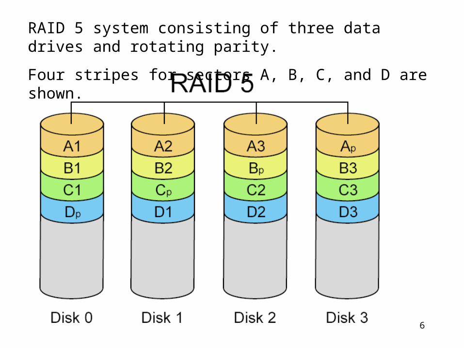
GF(28)• The GF log look up tables are generates based on what in
GF theory is called a primitive polynomial. Primitive polynomials have certain properties that lead to the error correction techniques.
• GF(28) is generated using the primitive polynomial
• This is the same primitive polynomials use to determine the feed back path for an 8-bit maximum count linear feedback shift registers (LFBSR’s).
• The LFBSR can be use to perform GF multiplication.
2 3 4 8( ) 1 (101110001)p X X X X X
22
The 8 bit LFBSR2 3 4 8( ) 1 (101110001)p X X X X X
Q7
12
3
QD
CLK
XOR21
2
3XOR21
2
3 XOR21
2
3
Q4
12
3
QD
CLK
101110001
Q6
12
3
QD
CLK
CLKQ5
12
3
QD
CLK
Q0
12
3
QD
CLK
Q2
12
3
QD
CLK
Q1
12
3
QD
CLK
Q3
12
3
QD
CLK
Q0 Q1 Q2 Q3 Q4 Q5 Q6 Q7
Or reversing order so that the most significant bit is at the left
Q61 2
3
Q D
CLK
Q51 2
3
Q D
CLK
Q41 2
3
Q D
CLK
Q21 2
3
Q D
CLK
Q31 2
3
Q D
CLK
XOR21
2
3Q0
1 2
3
Q D
CLK
XOR21
2
3Q7
1 2
3
Q D
CLK
CLK
Q11 2
3
Q D
CLK
XOR21
2
3
A shift has the same effect as 2. In VHDLQ <= Q(6) & Q(5) & Q(4) & (Q(3) XOR Q(7)) & (Q(2) XOR Q(7)) & (Q(1) XOR Q(7)) & Q(0) & Q(7);

23
1 Before shift
After ShiftX2
0 X7 X6
0 X6 X5
0 X5 X4
1 X4 X3X7
1 X3 X2X7
1 X2 X1X7
0 X1 X0
1 X0 X7
Q2
1 2
3
Q D
CLK
CLK
X2
X0XOR2
12
3
Q4
1 2
3
Q D
CLK
XOR21
2
3XOR21
2
3X6
Q6
1 2
3
Q D
CLK
X5
Q3
1 2
3
Q D
CLKX1
2X Q0
1 2
3
Q D
CLK
X4 X7
Q7
1 2
3
Q D
CLKX3
X7
Q1
1 2
3
Q D
CLK
Q5
1 2
3
Q D
CLK

24
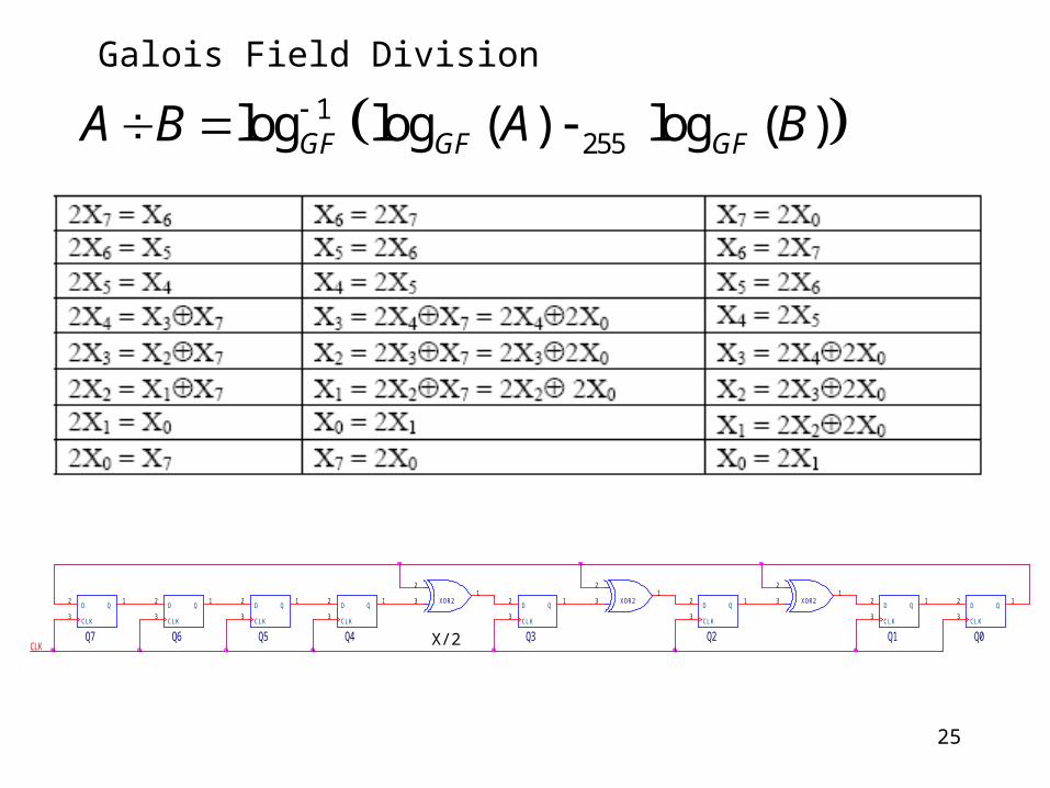
25
Q0
12
3
QD
CLK
Q7
12
3
QD
CLK
Q6
12
3
QD
CLK
XOR21
2
3
X/2CLK
XOR21
2
3
Q3
12
3
QD
CLK
Q1
12
3
QD
CLK
Q4
12
3
QD
CLK
Q5
12
3
QD
CLK
Q2
12
3
QD
CLK
XOR21
2
3
1255log log ( ) log ( )GF GF GFA B A B
Galois Field Division