1 RF background simulation: proposal for baseline simulation Video conference 22/9 -04 Rikard...
26
1 RF background simulation: proposal for baseline simulation Video conference 22/9 -04 Rikard Sandström Geneva University
-
date post
22-Dec-2015 -
Category
Documents
-
view
214 -
download
0
Transcript of 1 RF background simulation: proposal for baseline simulation Video conference 22/9 -04 Rikard...
1
RF background simulation: proposal for baseline
simulation
Video conference 22/9 -04
Rikard SandströmGeneva University
2
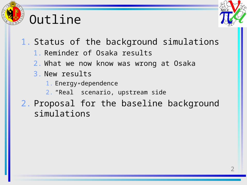
Outline
1. Status of the background simulations1. Reminder of Osaka results2. What we now know was wrong at Osaka3. New results
1. Energy dependence2. “Real” scenario, upstream side
2. Proposal for the baseline background simulations
3
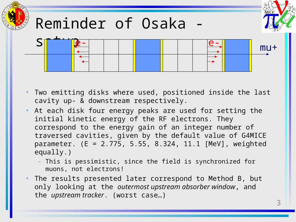
Reminder of Osaka - setup
• Two emitting disks where used, positioned inside the last cavity up- & downstream respectively.
• At each disk four energy peaks are used for setting the initial kinetic energy of the RF electrons. They correspond to the energy gain of an integer number of traversed cavities, given by the default value of G4MICE parameter. (E = 2.775, 5.55, 8.324, 11.1 [MeV], weighted equally.) – This is pessimistic, since the field is synchronized for muons, not
electrons!
• The results presented later correspond to Method B, but only looking at the outermost upstream absorber window, and the upstream tracker. (worst case…)
mu+e- e-
4
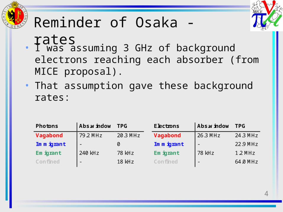
Photons Abs.window TPG
Vagabond 79.2 MHz 20.3 MHz
Immigrant - 0
Emigrant 240 kHz 78 kHz
Confined - 18 kHz
Electrons Abs.window TPG
Vagabond 26.3 MHz 24.3 MHz
Immigrant - 22.9 MHz
Emigrant 78 kHz 1.2 MHz
Confined - 64.0 MHz
Reminder of Osaka - rates
• I was assuming 3 GHz of background electrons reaching each absorber (from MICE proposal).
• That assumption gave these background rates:
5
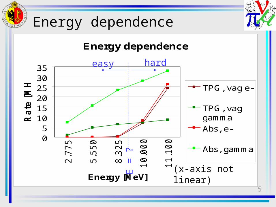
Energy dependence
05
101520253035
2.7
75
5.5
50
8.3
25
10
.00
0
11
.10
0Energy [MeV]
Ra
te [
MH
z]
TPG, vag e-
TPG, vaggamma
Abs, e-
Abs, gamma
Energy dependence
(x-axis not linear)
easy hard
E =
?
6
What we now know was wrong• There was a bug in the liquid hydrogen material description.– Fixed.
• There was a major bug in the absorber geometry. Only half was there! :( – This has now been fixed for flat windows.
• Asymmetry observed in June -04 simulations is gone.• Lower electrons rates leaving the cooling channel. (More
optimistic.)
– I am working right now on implementing curved windows as well.
• No news from the Geant4 group regarding the strange behavior of the physics in the absorbers as very dependent on the max allowed step length.– The problem was reproduced using a very simple
example and sent to the Geant4 group.

7
New results - setup
• These results are all with flat absorber windows, flat vacuum windows
• Absorbers use the new improved geometrical description.
• The RF electrons are emitted at disks right in front of the inner vacuum windows, and they are distributed uniformly over a radius of 15 cm. Energies are God-given.
• I have made no changes to the physics since Osaka.
8
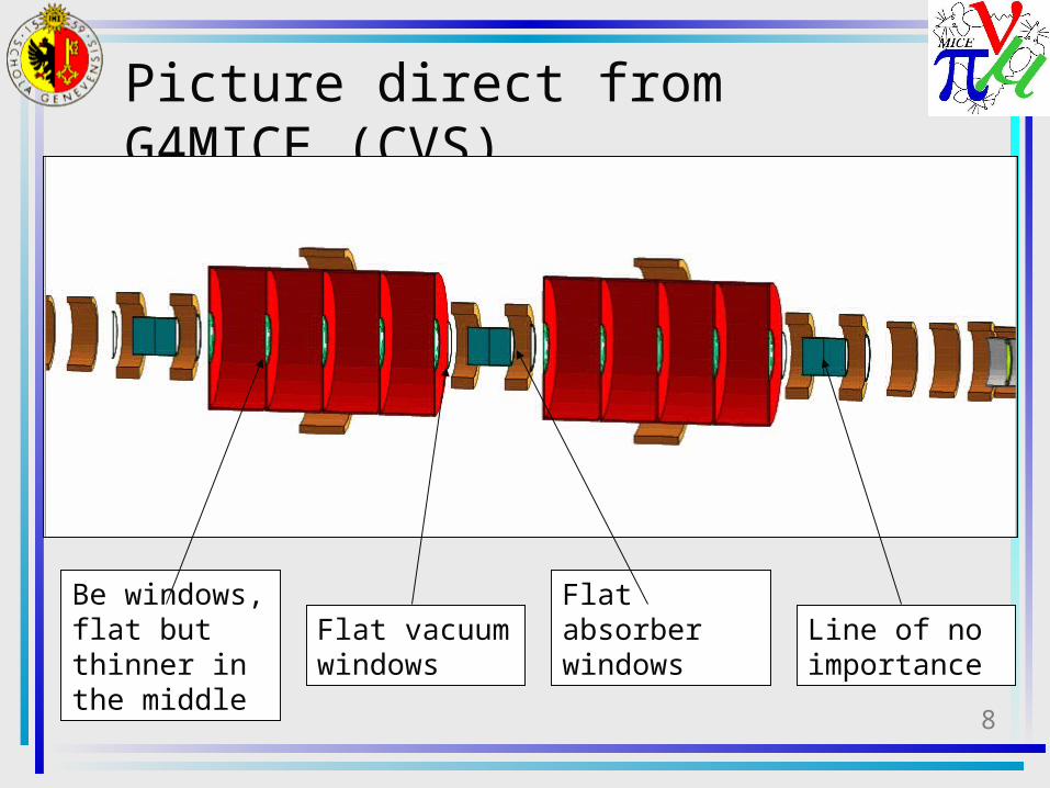
Picture direct from G4MICE (CVS)
Be windows, flat but thinner in the middle
Flat vacuum windows
Flat absorber windows
Line of no importance
9
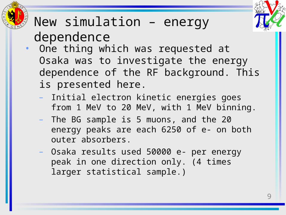
New simulation – energy dependence
• One thing which was requested at Osaka was to investigate the energy dependence of the RF background. This is presented here.– Initial electron kinetic energies goes from 1 MeV
to 20 MeV, with 1 MeV binning. – The BG sample is 5 muons, and the 20 energy
peaks are each 6250 of e- on both outer absorbers.
– Osaka results used 50000 e- per energy peak in one direction only. (4 times larger statistical sample.)
10
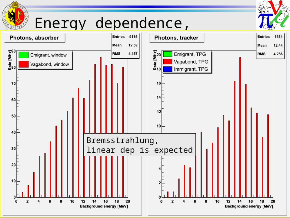
Energy dependence, photons
Bremsstrahlung, linear dep is expected
11
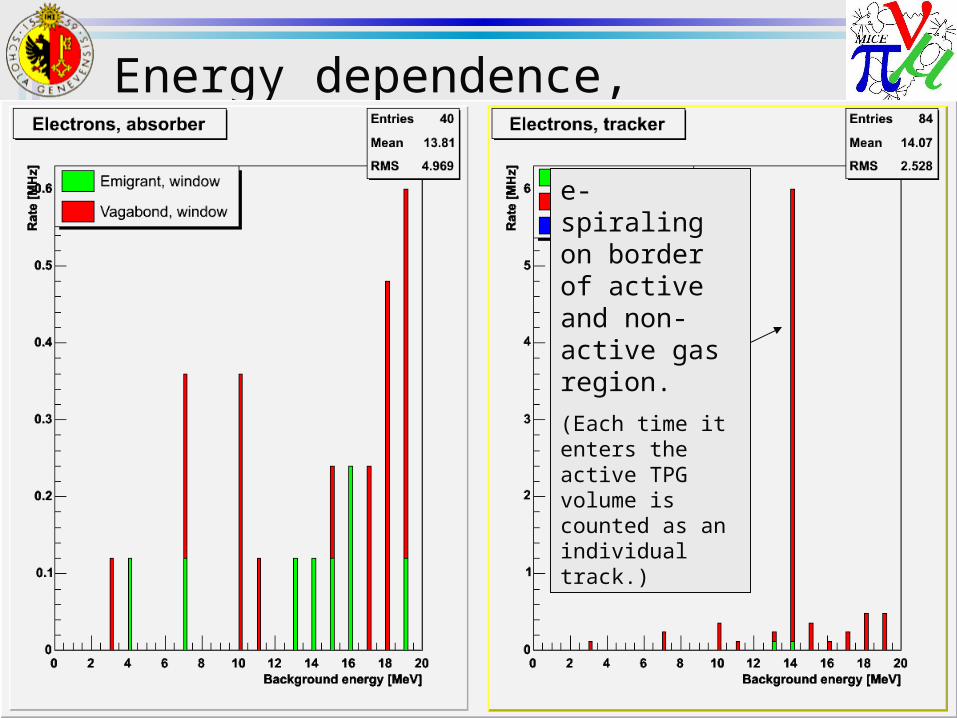
Energy dependence, electrons
e- spiraling on border of active and non-active gas region.
(Each time it enters the active TPG volume is counted as an individual track.)
12
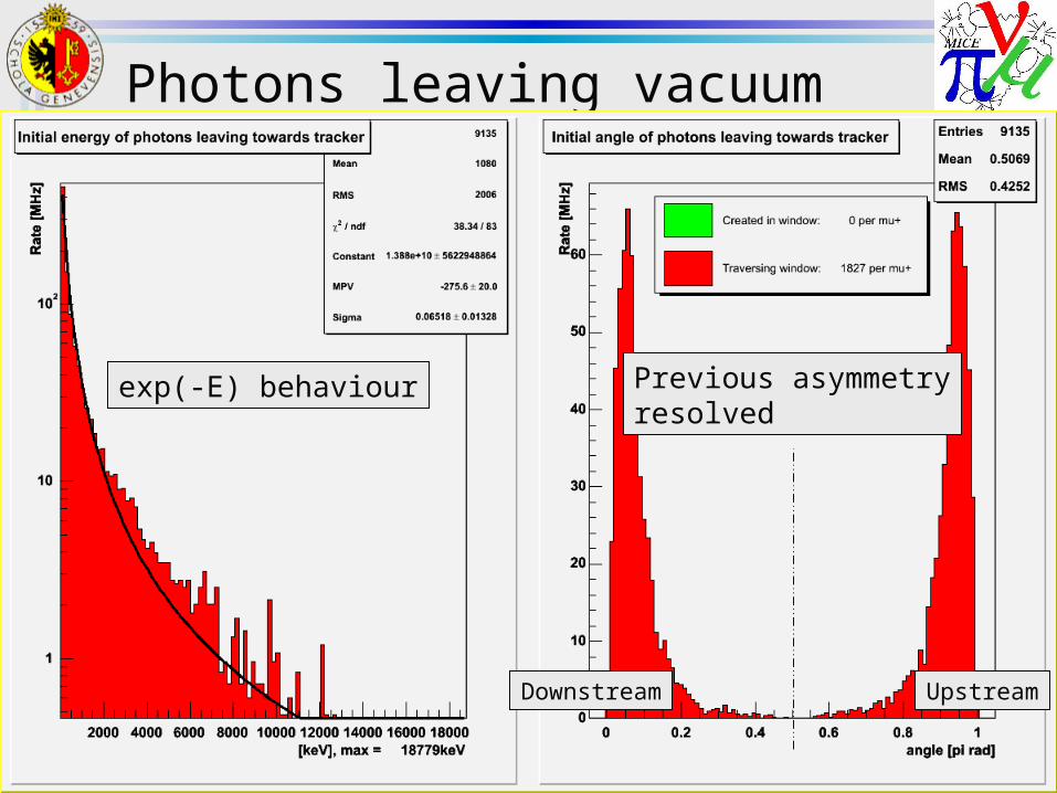
Photons leaving vacuum windows
Previous asymmetryresolved
exp(-E) behaviour
UpstreamDownstream
13
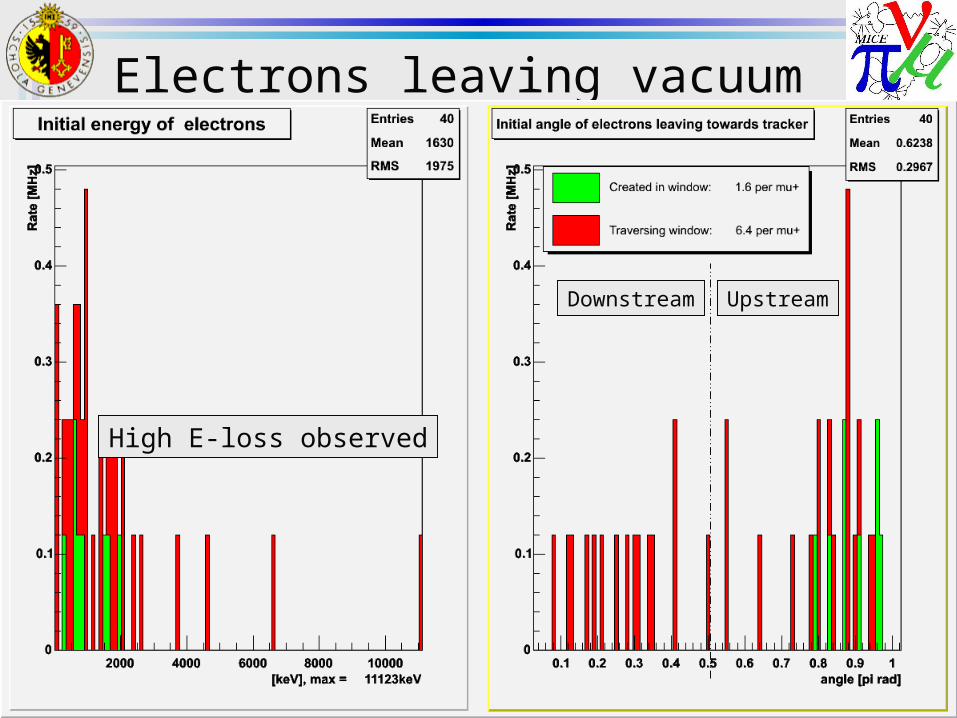
Electrons leaving vacuum window
High E-loss observed
UpstreamDownstream
14
New results – energy dependence
• Very few electrons leaves towards the tracker.– The fact that we see a weak energy dependence
suggests that they are mostly from photon conversion, not energy straggling.
– That 20% of the electrons are created inside the vacuum windows supports this idea. (How many are created by photons in the absorber windows?)
• These results were also the basis for an investigation of emission angle as a function of rho (at flat vacuum window). The results for photons is given on next slide.
15
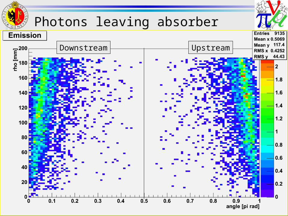
Photons leaving absorber windows
UpstreamDownstream
16
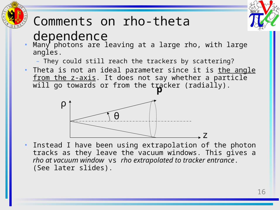
Comments on rho-theta dependence
• Many photons are leaving at a large rho, with large angles. – They could still reach the trackers by scattering?
• Theta is not an ideal parameter since it is the angle from the z-axis. It does not say whether a particle will go towards or from the tracker (radially).
• Instead I have been using extrapolation of the photon tracks as they leave the vacuum windows. This gives a rho at vacuum window vs rho extrapolated to tracker entrance. (See later slides).
p
θ
z
ρ
17
New simulation – “real” case• In order to investigate what our real background rates
are electrons were assumed to be emitted at peak field 8 MV/m, thus giving four energy peaks at E_kin = {1.3, 2.8, 5.1, 7.8} MeV.
• Only upstream side is simulated– Simulating only the worst direction
• Uniform spatial distribution of RF electrons, radius 15 cm, just in front of the vacuum window.
• Results are based on flat absorber windows and flat vacuum windows.
• Sample is based on a total of 100*(1 mu+ & 5000 e-)• On the first two slides, y-axis is particles leaving
absorber (or arriving at tracker) per initial e- of each E-peak separately. The third slide is per initial e- in total for all four peaks.
• The “tracker” in this case refers to the first plane of the TPG.
18
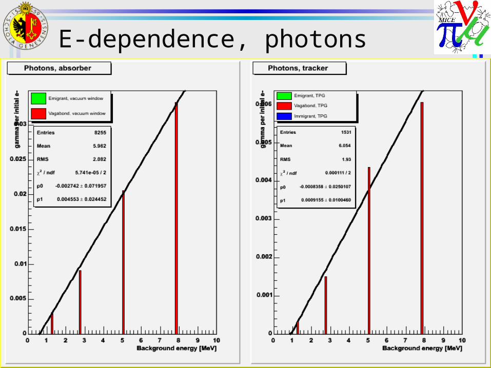
E-dependence, photons
19
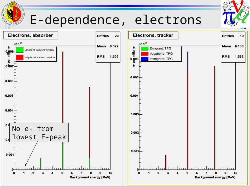
E-dependence, electrons
No e- from lowest E-peak

20
Energy when leaving vacuum win.
21
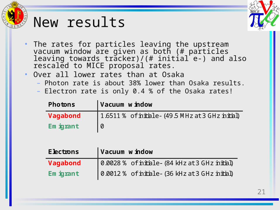
New results• The rates for particles leaving the upstream vacuum
window are given as both (# particles leaving towards tracker)/(# initial e-) and also rescaled to MICE proposal rates.
• Over all lower rates than at Osaka– Photon rate is about 38% lower than Osaka results.– Electron rate is only 0.4 % of the Osaka rates!
Electrons Vacuum window
Vagabond 0.0028 % of initial e- (84 kHz at 3 GHz initial)
Emigrant 0.0012 % of initial e- (36 kHz at 3 GHz initial)
Photons Vacuum window
Vagabond 1.6511 % of initial e- (49.5 MHz at 3 GHz initial)
Emigrant 0
22
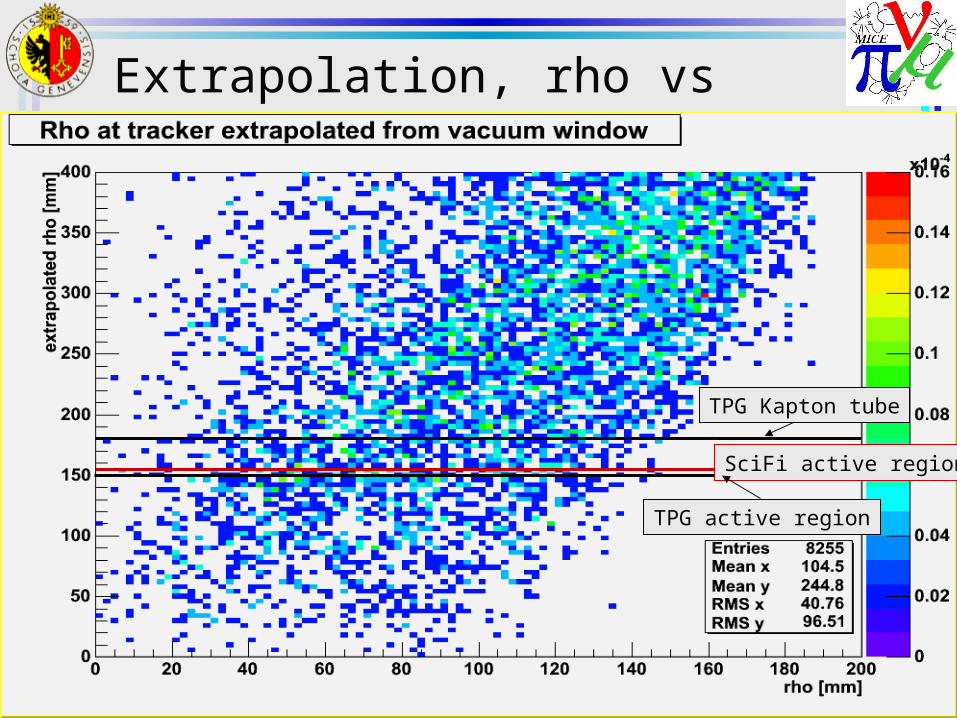
Extrapolation, rho vs xpol rho
TPG Kapton tube
TPG active region
SciFi active region
23
Comment on results• For photons, we observe the expected linear energy
dependence.• 18.5% of photons leaving absorber windows reach the
tracker (here the first plane of the TPG, radius 170 mm). • The extrapolated graph shows a rough linear dependence:
– rho_xpol = 2*rho_window– Extrapolation is to z = -4254 mm (the first SciFi plane) from z =
-2925 mm (the vacuum window).• For electrons, very few electrons leave the absorber system
and those have a weak energy dependence.– Electrons created by the photons in absorber and vacuum
windows.• Of the 19 of 20 e- leaving the vacuum window reach the
tracker (here the first plane of the TPG).• Running the same simulation without background, 20000
mu+, gives a negligible contribution to the background rates from the vacuum windows.
24
Proposal for baseline BG simulations
Assumptions & requirements1. Assume we are in Step V, (or that we are in
Step VI, but only a negligible number of e- and gamma traverse the central absorber)• Hence the background source can be treated as
contained in one RF-cell and closest outermost absorber.
2. Assume mu+ beam and upstream absorberThe results for upstream and downstream will be different due to the RF-field. Worst is upstream when RF optimized for mu+, and downstream when optimized for mu-.
25
Proposal assumptions & req. (cont)
3. Energy: Assume all electrons emitted at peak RF-field of 8 MV/m. This gives 4 peaks in energy at {1.3, 2.8, 5.1, 7.8} MeV for the worst direction (see point 2) (including E-loss in Be Windows)
4. Assume the four energy peaks to be weighted equally.5. The worst case is probably non-flip B-field. Should
baseline be flip B-field, optimized for beta = 42 cm optics? • Both situations should be simulated before we define the
baseline. 6. Simulate background using
1. Flat absorber windows, no vacuum windows2. Flat absorber windows, flat vacuum windows3. Curved absorber windows, no vacuum windows4. Curved absorber windows, curved vacuum
windows
26
Proposal assumptions & req. (cont)
8. The simulations should give a bank of electrons and photons at the entrance of the tracker volume.• Information in the bank will be (for each entry, lab frame)
1. positon (3-vector)2. momentum (3-vector)3. time4. particle ID5. parent particle ID6. kinetic energy of primary generated particle
9. We need statistics for a minimum of 25*106 initial e-.• (e- leaving absorbers)/(e- initial) = 4*10-5, would give 103
electrons in the bank. (this conclusion may change after no-flip mode is simulated)• On my machine this would take 21 days (per run).
10. All code used to create the results should be in CVS repository of G4MICE.
11. G4MICE should be able to use a saved bank of background to generate it right in front of the trackers.