1. Q1 - Free
14
1. Q1 Saturated ammonia vapour at a pressure of 14.7 bar is to be condensed to saturated liquid at a rate of 3,800 kg/h in a shell-and-tube heat exchanger with one shell pass and two tube passes. Cooling water flows through the tubes with an average velocity of 2.25 m/s. The cooling water enters the exchanger at 16 ◦ C and is to leave at 24 ◦ C. The tubes are made of brass having an inner diameter of 20 mm and an out diameter of 23 mm. The heat transfer coefficient for condensation on the outside of the tubes is 6,500 W/m 2 K. Using the tables provided and the data given below determine: i) the number of tubes per pass ii) the overall heat transfer coefficient based on the inner surface area of the tubes iii) the required tubes length per pass Datum: For flow inside the tubes, Nu =0.023Re 0.8 Pr 0.4 Heat transfer coefficient of the brass, k brass = 115 W/mK 1.1 Number of tubes per pass The figure 1 represents a sketch of the system. Saturated ammonia vapour at 14.7 bar T i = 38°C T 0 = 38°C Saturated liquid ammonia at 14.7 bar ˙ m NH 3 =3,800 kg/h t 0 = 24°C t i = 16°C Water V = 2.25 m/s Figure 1: Sketch of the heat exchanger 1
Transcript of 1. Q1 - Free

1. Q1
Saturated ammonia vapour at a pressure of 14.7 bar is to be condensed to saturatedliquid at a rate of 3,800 kg/h in a shell-and-tube heat exchanger with one shell passand two tube passes. Cooling water flows through the tubes with an average velocity of2.25 m/s. The cooling water enters the exchanger at 16 ◦C and is to leave at 24 ◦C.The tubes are made of brass having an inner diameter of 20 mm and an out diameterof 23 mm. The heat transfer coefficient for condensation on the outside of the tubes is6,500 W/m2K.
Using the tables provided and the data given below determine:i) the number of tubes per passii) the overall heat transfer coefficient based on the inner surface area of the tubesiii) the required tubes length per pass
Datum:
? For flow inside the tubes, Nu = 0.023Re0.8Pr0.4
? Heat transfer coefficient of the brass, kbrass = 115 W/mK
1.1 Number of tubes per pass
The figure 1 represents a sketch of the system.
Saturated ammonia vapourat 14.7 bar
Ti = 38°C
T0 = 38°C
Saturated liquid ammoniaat 14.7 bar
mNH3 = 3,800 kg/h
1
t0 = 24°C
ti = 16°C
WaterV = 2.25 m/s
Figure 1: Sketch of the heat exchanger
1

For water, at a mean temperature of 45 ◦C, from property tables:
Cp = 4,183 J/kgK µ = 1002× 10−6 kg/msk = 0.603 W/K Pr = 6.95
For saturated ammonia vapour at a pressure of 14.7 bar, from property tables:
hf,NH3 = 362,100 J/kg hg,NH3 = 1,472,600 J/kg
So,
hfg,NH3 = hg,NH3 − hf,NH3 = 1472600− 362100
= 1,110,500 J/kg
Water mass flow rate per tube
We can calculte the water mass flow rate per tube with:
mw,tube = V × ρw × Sw i.e. mw,tube = V × 1
νf,w
× πD2
4
where νf,w is the specific volume of water.
mw,tube = 2.25× 1
0.10018.10−2 ×π
(20.10−3
)2
4≈ 0.706 kg/s
Total water mass flow rate
An energy balance gives:
Q = mw × Cpw × (t0 − ti) = hfg,NH3 × mNH3
= mw × 4183× (24− 16) = 1110500× 0.706≈ 783,556 W
mw =783556
4183× (24− 16)
⇒ mw = 23.4 kg/s
Number of tubes =mw
mw,tube
=23.4
0.706
⇒ ≈ 33.2 tubes
So, as we decimal number of tubes, we have to arround on the superior number tobe sure that the ammonia will be condensed to saturated liquid.
2
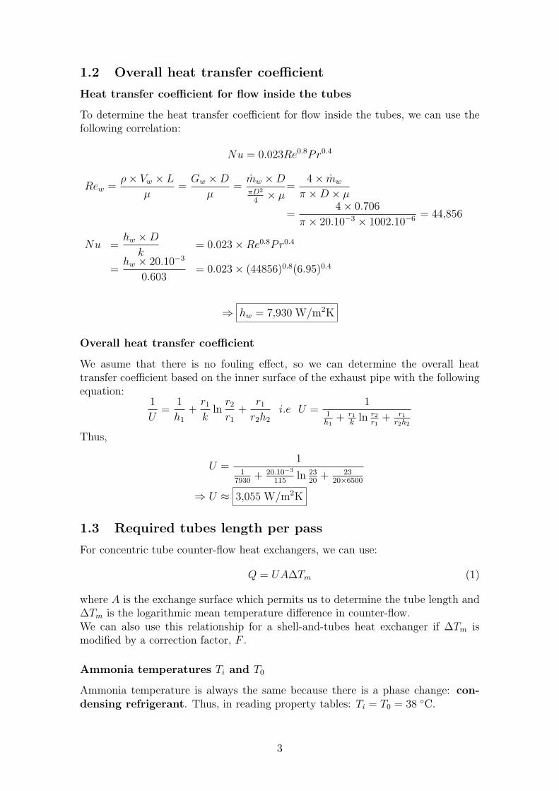
1.2 Overall heat transfer coefficient
Heat transfer coefficient for flow inside the tubes
To determine the heat transfer coefficient for flow inside the tubes, we can use thefollowing correlation:
Nu = 0.023Re0.8Pr0.4
Rew =ρ× Vw × L
µ=
Gw ×D
µ=
mw ×DπD2
4× µ
=4× mw
π ×D × µ
=4× 0.706
π × 20.10−3 × 1002.10−6 = 44,856
Nu =hw ×D
k= 0.023×Re0.8Pr0.4
=hw × 20.10−3
0.603= 0.023× (44856)0.8(6.95)0.4
⇒ hw = 7,930 W/m2K
Overall heat transfer coefficient
We asume that there is no fouling effect, so we can determine the overall heattransfer coefficient based on the inner surface of the exhaust pipe with the followingequation:
1
U=
1
h1
+r1
kln
r2
r1
+r1
r2h2
i.e U =1
1h1
+ r1
kln r2
r1+ r1
r2h2
Thus,
U =1
17930
+ 20.10−3
115ln 23
20+ 23
20×6500
⇒ U ≈ 3,055 W/m2K
1.3 Required tubes length per pass
For concentric tube counter-flow heat exchangers, we can use:
Q = UA∆Tm (1)
where A is the exchange surface which permits us to determine the tube length and∆Tm is the logarithmic mean temperature difference in counter-flow.We can also use this relationship for a shell-and-tubes heat exchanger if ∆Tm ismodified by a correction factor, F .
Ammonia temperatures Ti and T0
Ammonia temperature is always the same because there is a phase change: con-densing refrigerant. Thus, in reading property tables: Ti = T0 = 38 ◦C.
3
Logarithmic mean temperature difference ∆Tm
∆Tm(CF ) =(38− 24)− (38− 16)
ln
(38− 24
38− 16
) = 17.7 K
Area and length tube
From equation 2, we can have the total exchange surface:
A =Q
U ×∆Tm
=1110500
3055× 17.7= 20.5 m2
and then the area per tube, Atube:
Atube =20.5
2× 34= 0.3015 m2 = πDL
Finally, the tube length L is equal to:
L =Atube
πD=
0.3015
π × 20.10−3
⇒ L = 4.8 m
4

2. Q2
As part of a combined heat and power scheme, the exhaust gas from a large diesel engineis to be cooled from 400 ◦C to 150 ◦C in a concentric tube counter-flow heat exchanger.Part of the exhaust pipe, which is made of stainless steel, forms the inner tube of theheat exchanger and has an internal diameter of 80 mm and a wall thickness of 3 mm.Cooling water flows in the annular space of the exchanger and enters at 40 ◦C. Theheat transfer coefficient between the exhaust gas and the inner surface of the exhaustpipe is 250 W/m2K and between the outer surface of the exhaust pipe and the water is1,400 W/m2K. The gas flow rate is 240 kg/h and the water flow rate is 1,600 kg/h.
Using the information given below, determine including radius effects:i) the overall heat transfer coefficient based on the inner surface of the exhaust pipeii) the required length of the exchangeriii) the effectiveness of the exchanger
Data:
? Specific heat of gas, Cpg = 1.14 kJ/kgK
? Specific heat of water, Cpw = 4.18 kJ/kgK
? Thermal conductivity of stainless steel, k = 18 W/mK
2.1 Overall heat transfer coefficient
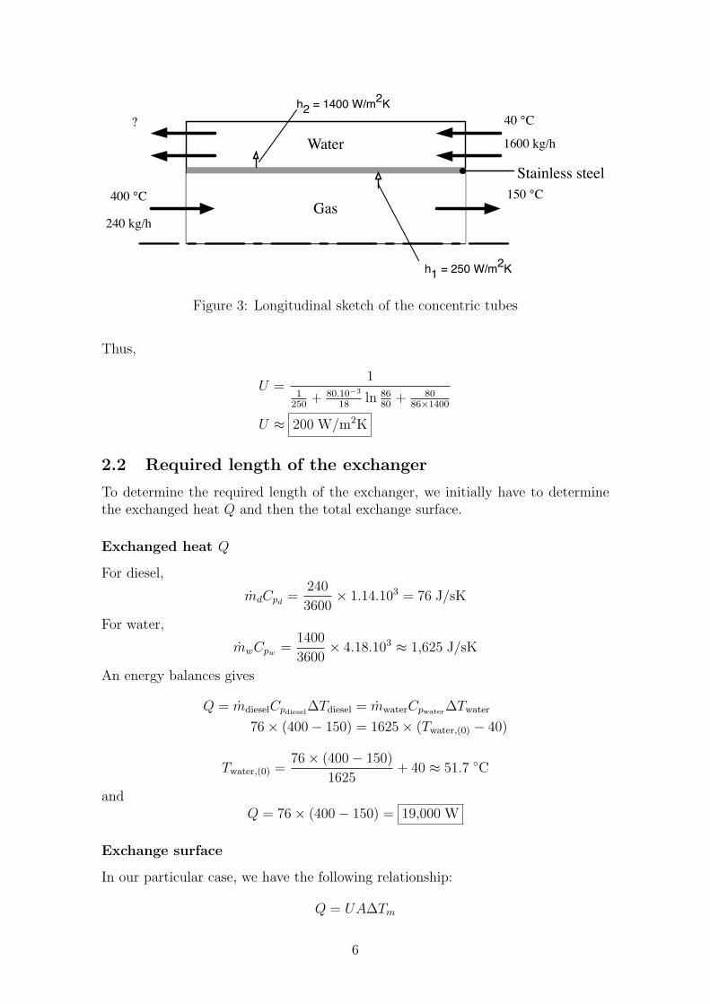
The figures 2 and 3 represent sketchs of the system.
Water
Gas
Figure 2: Cross-sectional sketch of the concentric tubes
We are in the case of a concentric tube counter-flow heat exchanger and we asumethat there is no fouling effect, so we can determine the overall heat transfer coefficientbased on the inner surface of the exhaust pipe with the following equation:
1
U=
1
h1
+r1
kln
r2
r1
+r1
r2h2
i.e U =1
1h1
+ r1
kln r2
r1+ r1
r2h2
5
Water
Gas
Stainless steel150 °C
h1 = 250 W/m2K
h2 = 1400 W/m2K40 °C?
400 °C
240 kg/h
1600 kg/h
Figure 3: Longitudinal sketch of the concentric tubes
Thus,
U =1
1250
+ 80.10−3
18ln 86
80+ 80
86×1400
U ≈ 200 W/m2K
2.2 Required length of the exchanger
To determine the required length of the exchanger, we initially have to determinethe exchanged heat Q and then the total exchange surface.
Exchanged heat Q
For diesel,
mdCpd=
240
3600× 1.14.103 = 76 J/sK
For water,
mwCpw =1400
3600× 4.18.103 ≈ 1,625 J/sK
An energy balances gives
Q = mdieselCpdiesel∆Tdiesel = mwaterCpwater∆Twater
76× (400− 150) = 1625× (Twater,(0) − 40)
Twater,(0) =76× (400− 150)
1625+ 40 ≈ 51.7 ◦C
andQ = 76× (400− 150) = 19,000 W
Exchange surface
In our particular case, we have the following relationship:
Q = UA∆Tm
6
where ∆Tm is the logarithmic mean temperature difference and A the exchange area.
∆Tm =(400− 51.7)− (150− 40)
ln
(400− 51.7
150− 40
) = 206.7 ◦C
Thus,
A =Q
U∆Tm
=19000
200× 206.7= 0.46 m2
However A = πDL i.e. L =A
πD
L =0.46
π × 80.10−3 ⇒ L ≈ 1.83 m
2.3 Effectiveness of the exchanger
The effectiveness of the exchanger is equal to:
ε =Q
Qmax
where Qmax = Cmin × (Tdiesel,(i) − Twater,(i))Here Cmin is equal to mdCpd
because mdCpd< mwCpw .
Thus, we have:
ε =19000
76× (400− 40)= 0.694
7

3. Q3
A shell-and-tube heat exchanger is to cool 10,800 kg/h of hot lubricating oil from 158 ◦Cto 90 ◦C. The oil shell pass with an average heat transfer coefficient of 430 W/m2K.Cooling water passes through the tubes, entering the exchanger at 14 ◦C and leaving at76 ◦C. There are 4 tubes passes, each with 12 tubes. The tubes are 30 mm diameterand thin - walled.
Using the information provided show that the heat transfer coefficient for flow inside thetubes is approximately 1,440 W/m2K.
Hence determinei) the overall heat transfer coefficientii) the required tube length per pass
Datum:
? For flow inside the tubes, Nu = 0.023Re0.8Pr0.4
? For oil, Cp = 2,350 J/kgK
3.1 Heat transfer coefficient for flow inside tubes
The figure 4 represents a sketch of the system.
Hot lubricating oil
Ti = 158 °C
T0 = 90 °C
t0 = 76 °C
ti = 14 °C
Water
moil = 10,800 kg/h = 3 kg/s
1
Figure 4: Sketch of the heat exchanger
For water, at a mean temperature of 45 ◦C, from property tables:
Cp = 4,181 J/kgK µ = 594× 10−6 kg/msk = 0.638 W/K Pr = 3.89
8

An energy balance gives:
Q = mw × Cpw × (t0 − ti) = moil × Cpoil× (Ti − T0)
= mw × 4,181× (76− 14) = 3× 2,350× (158− 90)= 479,400 W
and mw = 1.85 kg/s
The water rate flow per tube = 1.85/12 = 0.1542 kg/s
Rew=ρ× Vw × L
µ=
Gw ×D
µ=
mw ×DπD2
4× µ
=4× mw
π ×D × µ
=4× 0.1542
π × 30.10−3 × 594.10−6 = 11,018
To calculate the heat transfer coefficient inside tubes, we use the definition of Nusseltnumber and the given relationship between Nu, Re and Pr.
Nu =hw ×D
k= 0.023×Re0.8Pr0.4
=hw × 30.10−3
0.638= 0.023× (11,018)0.8(3.89)0.4
⇒ hw = 1,442 W/m2K
3.2 Overall heat transfer coefficient
To calcultate the overall heat transfer coefficient, as we asume that the tubes arethin-walled we have the following equation:
1
U=
1
h1
+1
h2
+ R′f1 + R′
f2︸ ︷︷ ︸= 0
Thus,1
U=
1
430+
1
1442⇒ U = 331 W/m2K
3.3 Required tube length per pass
For concentric tube counter-flow heat exchangers, we can use:
Q = UA∆Tm (2)
where A is the exchange surface which permits us to determine the tube lengthand ∆Tm is the logarithmic mean temperature difference in contraflow which iscalculated with the formula:
9

∆Tm =∆T2 −∆T1
ln
(∆T2
∆T1
)water
oil
1 2length
temperature
Air mass flow rate
Air mass flow rate was calculated by the given formula:
Air mass flow rate ma (kg/h) = 3.0
√h
T(H +
h
13.6
h = pressure drop across nozzle in mmof waterH = barometric pressure in mmof MercuryT = absolute air temperature upstream of nozzle, K
As water mass flow rate, we calculate the air mass per unit area:
Ga =ma
Aa
where Aa is the cross area for air flow = π × (12.7× 10⁻³)2 ≈ 1.265× 10⁻⁴ m2
1.4.2 Heat transferred
We calculate heats transferred (kJ/s) with the following formula:Qw = heat transferred to cooling water = mwCpw∆Tw
Qa = heat transferred from air = maCpa∆Ta
Cpw was read in the graph given with the subject and Cpa in the steam tables. We can observethat Qw and Qa are quiete closely.
1.4.3 Overall heat transfer coefficient
The overall heat transfer coefficient based on the mean diameter (6.07× 10⁻² m2):
U = overall heat transfer coefficient =Q× 105
6.07∆TmW/m2K
where ∆m is the logarithmic mean temperature in contra flow
=∆T2 −∆T1
ln
(∆T2
∆T1
)
water
air
1 2length
temperature
Figure 1.2: Diagram explain the logarithmicmean temperature difference in contra flow
2
Figure 5: Diagram explaining the logarithmicmean temperature difference in contra flow
We can also use it for a shell-and-tubes heat exchanger if ∆Tm is modified by acorrection factor, F .
Logarithmic mean temperature difference ∆Tm
∆Tm(CF ) =(158− 76)− (90− 14)
ln
(158− 76
90− 14
) = 79 K
and
R =Ti − T0
t0 − ti=
158− 90
76− 14= 1.1
P =t0 − tiTi − ti
=76− 14
158− 14= 0.43
⇒ F = 0.88
So ∆Tm = 79× 0.88 ≈ 69.5 K
Area and length tube
From equation 2, we can have the total exchange surface:
A =Q
U ×∆Tm
=479400
331× 69.5= 21.8 m2
and then the area per tube, Atube:
Atube =21.8
4× 12= 0.454 m2 = πDL
Finally, the tube length L is equal to:
L =Atube
πD=
0.454
π × 30.10−3
⇒ L = 4.8 m
10
4. Q4
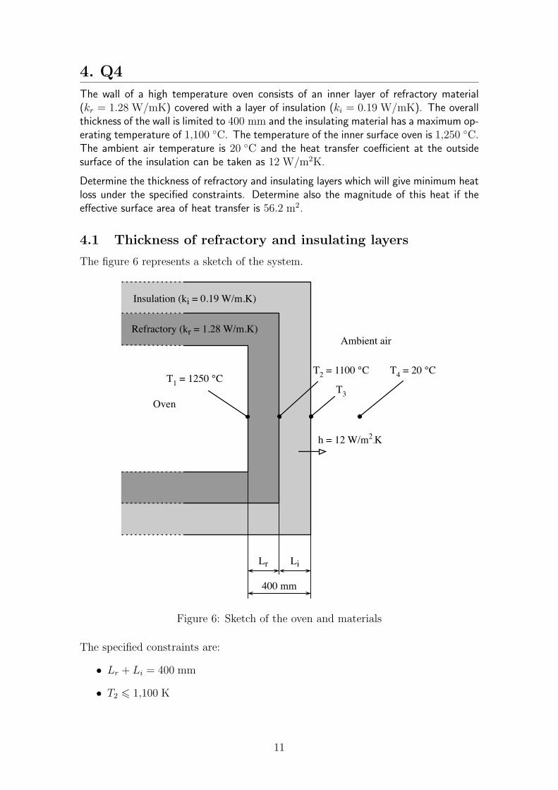
The wall of a high temperature oven consists of an inner layer of refractory material(kr = 1.28 W/mK) covered with a layer of insulation (ki = 0.19 W/mK). The overallthickness of the wall is limited to 400 mm and the insulating material has a maximum op-erating temperature of 1,100 ◦C. The temperature of the inner surface oven is 1,250 ◦C.The ambient air temperature is 20 ◦C and the heat transfer coefficient at the outsidesurface of the insulation can be taken as 12 W/m2K.
Determine the thickness of refractory and insulating layers which will give minimum heatloss under the specified constraints. Determine also the magnitude of this heat if theeffective surface area of heat transfer is 56.2 m2.
4.1 Thickness of refractory and insulating layers
The figure 6 represents a sketch of the system.
Oven
Refractory (kr = 1.28 W/m.K)
Insulation (ki = 0.19 W/m.K)
Ambient air
Lr Li
400 mm
h = 12 W/m2.K
T1 = 1250 °CT2 = 1100 °C
T3
T4 = 20 °C
Figure 6: Sketch of the oven and materials
The specified constraints are:
• Lr + Li = 400 mm
• T2 6 1,100 K
11
We are looking for the minimum heat loss under the specified constraints. Howeverwe know that bigger is the layer of insulation, better is the heat loss1, so we arelooking for the biggest layer of insulation. As we have the constraint on the layerlengths, bigger is the layer of the insulating material, nearer it is of the oven andof the oven temperature (T1 = 1,250 ◦C). Thus, we have to determine the length ofthe insulating material so that T2 is equal to 1,100 K.
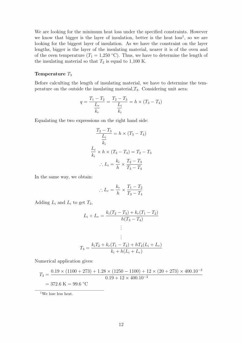
Temperature T3
Before calculting the length of insulating material, we have to determine the tem-perature on the outside the insulating material,T3. Considering unit aera:
q =T1 − T2
Lr
kr
=T2 − T3
Li
ki
= h× (T3 − T4)
Equalating the two expressions on the right hand side:
T2 − T3
Li
ki
= h× (T3 − T4)
Li
ki
× h× (T3 − T4) = T2 − T3
∴ Li =ki
h× T2 − T3
T3 − T4
In the same way, we obtain:
∴ Lr =kr
h× T1 − T2
T3 − T4
Adding Li and Li to get T3,
Li + Lr =ki(T2 − T3) + kr(T1 − T2)
h(T3 − T4)...
...
T3 =kiT2 + kr(T1 − T2) + hT4(Li + Lr)
ki + h(Li + Lr)
Numerical application gives:
T3 =0.19× (1100 + 273) + 1.28× (1250− 1100) + 12× (20 + 273)× 400.10−3
0.19 + 12× 400.10−3
= 372.6 K = 99.6 ◦C
1We lose less heat.
12

Lengths of materials
Thus we can determine the layer of insulation length,
Li =0.19
12× (1100− 99.6)
(99.6− 20)
∴ Li = 0.199 m = 199 mm
Therefore,
Lr = 400− Li
= 400− 199
∴ Lr = 201 mm
4.2 Magnitude of this heat
To determine the magnitude of this heat if the effective surface area of heat transferis 56.2 m, we just have to multiply q by the area:
Q = q × A
= h× (T3 − T4)× A
= 12× (99.6− 20)× 56.2
∴ Q = 53,682 W
4.3 Complements
As I find this exercise very interesting, I wondered how Lr, Li and q evolve againstT2. So, the graph 7 page 14 shows the different curves. It is interesting to observethat Lr and Li are not linear, but that q is linear.
13

0
0.05
0.1
0.15
0.2
0.25
0.3
0.35
0.4
0.45
0 200 400 600 800 1000 1200 1400
T2 (°C)
Lr
or
Li
(m)
0
500
1000
1500
2000
2500
3000
3500
q (
W/m
^2
)Li Lr q Limit T2 = 1100 °C
Figure 7: Graph Lr, Li and q against T2
14