

1. Plant description - · PDF fileThermal Waste Treatment ... Heat Boiler Pushing Grate...
13
-
Upload
vuongthuan -
Category
Documents
-
view
215 -
download
2
Transcript of 1. Plant description - · PDF fileThermal Waste Treatment ... Heat Boiler Pushing Grate...

231
Thermal Waste Treatment Plant Spittelau
Thermal Waste Treatment Plant Spittelau – New Construction to the Existing Plant –
Frank Schumacher, Philipp Krobath, Erich Pawelka, Ulrich Ponweiser and Martin Höbler
1. Plant description .........................................................................................231
2. Changes over the years ...............................................................................232
2.1. A new era .....................................................................................................232
2.2. Considerations ............................................................................................233
2.3. Implementation ...........................................................................................234
3. Scope of supply MH Power Systems Europe Service – MHPS-ES – ....235
4. Disassembly ................................................................................................238
5. Assembly ......................................................................................................239
6. Challenges, particularities and conclusion ..............................................240
1. Plant descriptionThe thermal waste treatment plant Spittelau is steeped in history and tradition. It is one out of four municipal solid waste incinerations plants in Vienna. The plant was built from 1969 until 1971 for the purpose of thermal utilization of municipal waste and household-type commercial waste as well as energy supply of the new General Hospital Vienna two kilometres away via district heating. The plant was equipped with two hot-water boilers to ensure heat supply at all times. Although it is located in the town-centre of Vienna its architectural structure did not differ significantly from the traditional plant structure.
After only six years the plant had utilized one million tonnes of waste. Throughout the following years, pipeline construction over long distances intensified and by 1985 a closed circular pipeline for heating supply had been built around the entire inner city district of Vienna. Among many others, the parliament, the Vienna Burgtheater and the Vienna City Hall, were the first customers of the company Heizbetriebe Wien. The number of supplied buildings increased steadily and the technical plant was further enlarged and adapted to the state-of-the-art. Until today, the pipeline system has been provided with hot water supply from waste incineration plants such as WIP Flötzersteig, hazardous waste incineration plant Simmeringer Haide, WIP Pfaffenau, other decentralised plants – Arsenal, Kagran, Leopoldau, Inzersdorf – as well as the cogeneration of the larger power plant Simmering and power plant Donaustadt units.

Frank Schumacher, Philipp Krobath, Erich Pawelka, Ulrich Ponweiser, Martin Höbler
232
Figure 1: Closed circular pipeline around the inner city district of Vienna
2. Changes over the years
2.1. A new era 1987 would become a crucial year in the development of the company Unter-nehmen Fernwärme as a success story – today: Wien Energie . A fire during an outage for revision destroyed a large part of the plant in May 1987. Some called for a complete shut-down of the entire plant immediately. The massive destruction, however, represented a great opportunity as well. The City of Vienna seized this opportunity to reinforce its commitment to green waste treatment and opted for reconstruction of the plant. The people of Vienna were closely integrated into the reconstruction process.Figure 2: Thermal waste treatment plant
Spittelan before retrofit
officebuilding
town hall
converterstation
apartments
generalhospital UNO-City
heat and powerstation Leopoldau
heat and powerstation OMV
heat andpower stationDonaustadt
heat and powerstation Arsenal
heat and powerstation
Simmering
heating plantsKagran
heating plantsInzersdorf
industrialbuilding
DONAU
thermaltreatment plants
Pfaffenau
thermaltreatment plants
Simmeringer Haide
thermaltreatment plantsFlötzersteig
thermaltreatment plants
Splittelau

233
Thermal Waste Treatment Plant Spittelau
Reconstruction comprised the installation of a state-of-the-art flue gas purification plant, a DeNOx system, and a dioxin destruction system. The famous artist and envi-ronmental campaigner Friedensreich Hundertwasser designed the façade of the plant. Thanks to his work the reconstructed plant became internationally popular as a work of great artistic merit and a monument to Hundertwasser himself. The waste heat boilers and the peak-load boilers were renewed as well. Spittelau’s emission levels set a new international standard and the plant still has some of the best emission levels in Europe.
2.2. Considerations The thermal waste treatment plant operates with an average throughput capacity of 250,000 tonnes per year and a district heating output of 60 MWt per hour. The pipeline network has been further expanded up to a length of approximately 1,200 kilometers. 330,000 Viennese households and about 6,500 major energy consumers are currently supplied with heat.
Meanwhile, Fernwärme Wien has started another supply service: district cooling. In 2006, Wien Energy commissioned of one of the first district cooling plants in Town-Town. Spittelau followed with the construction of a new central cooling plant with a cooling capacity of 17 MWth in total. District cooling consumers are mainly large-scale consumers such as the General Hospital, Vienna. Existing pipelines for district heating are used for district cooling supply during the summer season.
The system of separately collected waste materials in private households and businesses as well as a change in consumer behaviour led to a sharp increase in calorific value and the plant’s throughput decreased accordingly.
The plant faced serious challenges such as new technologies on the market and rising costs for the plant’s operation and maintenance. In addition, some plant parts from the original construction phase had been in operation for more than forty years. Therefore, in 2006/2007, Wien Energie started first reflections on how to make the plant more profitable, ecologically sound and fit for the future.
When the management finally decided on a plant upgrade in 2009 further preparation works started and the official approval procedure was initiated. After obtaining approval for construction, the management, in accordance to public procurement law, carried out an international call for tenders for the first lot.
Damage to the waste treatment plant of the Wärmeverbund Mitte caused a delay in the implementation of the project Spittelau in 2010. During the time-lag, project planning was re-evaluated whereby the electrostatic precipitators were replaced with new fabric filters. The design and parameters of the filters’ internal parts and spare parts correspond to those of the sister plant Flötzensteig. The similarity allows for an uncomplicated exchange of single parts and spare parts among the two plants and, consequentially, facilitates maintenance and keeps costs at a minimum.
Frank Schumacher, Philipp Krobath, Erich Pawelka, Ulrich Ponweiser, Martin Höbler
234
2.3. ImplementationDespite the delay, the management stuck to the main objective of a full retrofit and preparatory works were resumed by the end of 2010 whereby civil works were divided into several lots.
There are seven main lots – VE – which were awarded within contracting management:
• VEconstruction Constructionproject,facadeandotherauxiliaries• VEFiring Boilerplant,wastefeedingsystem,fabricfilter,
ash removal system, cooling water system • VEWater-Steam Piping,converters,feedwaterandcondensatesystem,
exhaust steam system• VETurbine Turbo-generator• VESCR Catalyticfluegascleaningplant,heatexchanger• VEEMSR Plantcabling–IE&C–,renewinglow-voltagedistribution• VEDemo Plantdisassemblingandtransportofdismantledmaterial
Only the original two-stage flue gas wet scrubber including the waste water treatment system will remain after retrofit. A call for tender for connection to the control system was not necessary since current contracts apply for retrofit works as well.
The following components have been or are currently retrofitted:
• Renewingwasteheatboiler1and2• Replacingelectrostaticprecipitatorwithfabricfilters• InstallingofactivatedHOKinjectionupstreamofthefabricfilter• RenewingtheDeNOxsystemwithlow-temperaturecatalyst• Renewingthehotwatersupplysystem• Renewingtheconverters• Renewingturbinesandgenerators• Renewingashremovalsystem,includingactivatedHOK• Renewingwater-steam-system
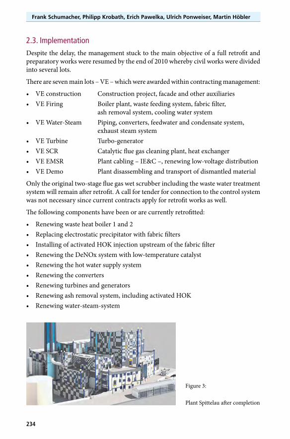
Figure 3:
Plant Spittelau after completion

235
Thermal Waste Treatment Plant Spittelau
Through optimization in energy management power generation will increase threefold while district heat extraction remains stable and the consumption of natural gas as primary energy for the DeNOx plant is reduced by roughly 5M m3.
Both incineration lines of the thermal waste treatment plant Spittelau are identical in design. The main components before and after retrofit are listed below.
Table 1: Technical data of the main components before and after retrofit Original New /RetrofitBoilerManufacturer Waagner Biro MHPS-ES
Boiler type natural circulation natural circulation
Heating surface m² 2,420 5,001
Drum content m³ 20 20
Steam capacity t/h 45 – Saturated Steam – 60.5
Live steam pressure boiler – upstream turbine – bar 32 40
Live steam temperature °C 238 400
Combustion GrateManufacturer Martin MHPS-ES
Design reciprocating grate pusher grate
Firing system counterflow centerflow
Waste throughput Mg/h per line 16-18 16
Calorific design value – Hu – MJ/kg 9 10
Thermal input fuel MWth 41.1 44.5
Grate surface m² 34.5 62
Flue Gas CleaningManufacturer AE&E MHPS-ES
Number per line 1 1
Procedure electricstatic precipitator fabric filter with 2-step wet scrubber DeNOX system
SCR SCR- DeNOX system
Flue gas amount Nm³/h per line 85,000 116,000
With the renewed catalyst plant, the heating of the flue gas with natural gas has become obsolete. This step will be accomplished via heat exchangers which are cleaned with steam soot blowers.
The contractor MHPS-ES provided the required expertise and know-how for accom-plishing these works during full plant operation.
3. Scope of supply MH Power Systems Europe Service – MHPS-ES –MHPS-ES was awarded the contract for implementing a complete, operational and perfectly functioning firing and boiler plant for combustion of municipal waste and household-type commercial waste. The scope of supply included delivery, assembling, and commissioning.

Frank Schumacher, Philipp Krobath, Erich Pawelka, Ulrich Ponweiser, Martin Höbler
236
Was
te H
eat
Bo
iler
Push
ing
Gra
te
Co
mb
ust
ion
Air
Sys
tem
Star
t-u
p a
nd
Au
xilia
ry B
urn
er
Fab
ric
Filt
er
Ash
Rem
ova
l Sys
tem
and
Ash
Silo
No
. 1
Slag
Rem
ova
l Sys
tem
Co
olin
g W
ater
Pla
nt
Stee
l Co
nst
ruct
ion
Bo
iler/
Bo
iler
Ho
use
Insu
lati
on
Figu
re 4
: Sc
ope
of su
pply
by
MH
Pow
er S
yste
ms E
urop
e Se
rvic
e G
mbH
237
Thermal Waste Treatment Plant Spittelau
The scope of supply for the lot firing comprises the following main components:
• Wasteheatboiler
• Pushinggrate
• Combustionairsystem
• Startupandauxiliaryburner
• Slagremovalsystem
• Flyashremoval
• FabricfilterwithinstalleddosageofactivatedHOK
• Coolingwaterplant
• Steelconstructionboiler/boilerhouse
• Insulation
• Temporarysolutionsforon-goingoperationofonewasteincinerationlineduringretrofit
• Delivery,assembly,commissioning,trialoperation
• Training
• DocumentationProject Schedule
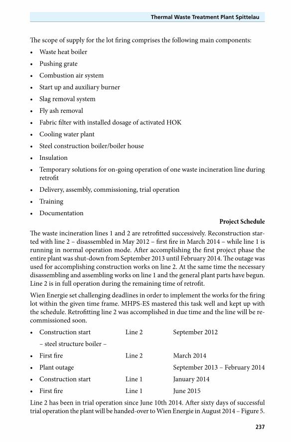
The waste incineration lines 1 and 2 are retrofitted successively. Reconstruction star-ted with line 2 – disassembled in May 2012 – first fire in March 2014 – while line 1 is running in normal operation mode. After accomplishing the first project phase the entire plant was shut-down from September 2013 until February 2014. The outage was used for accomplishing construction works on line 2. At the same time the necessary disassembling and assembling works on line 1 and the general plant parts have begun. Line 2 is in full operation during the remaining time of retrofit.
Wien Energie set challenging deadlines in order to implement the works for the firing lot within the given time frame. MHPS-ES mastered this task well and kept up with the schedule. Retrofitting line 2 was accomplished in due time and the line will be re-commissioned soon.
• Constructionstart Line2 September2012
– steel structure boiler –
• Firstfire Line2 March2014
• Plantoutage September2013–February2014
• Constructionstart Line1 January2014
• Firstfire Line1 June2015
Line2hasbeenintrialoperationsinceJune10th2014.Aftersixtydaysofsuccessfultrial operation the plant will be handed-over to Wien Energie in August 2014 – Figure 5.
Frank Schumacher, Philipp Krobath, Erich Pawelka, Ulrich Ponweiser, Martin Höbler
238
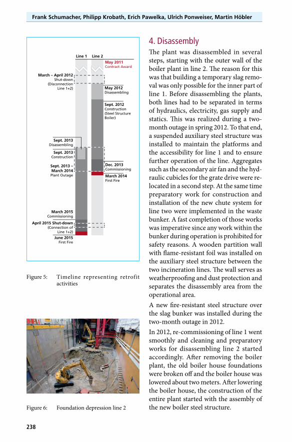
4. Disassembly The plant was disassembled in several steps, starting with the outer wall of the boiler plant in line 2. The reason for this was that building a temporary slag remo-val was only possible for the inner part of line 1. Before disassembling the plants, both lines had to be separated in terms of hydraulics, electricity, gas supply and statics. This was realized during a two-month outage in spring 2012. To that end, a suspended auxiliary steel structure was installed to maintain the platforms and the accessibility for line 1 and to ensure further operation of the line. Aggregates such as the secondary air fan and the hyd-raulic cubicles for the grate drive were re-located in a second step. At the same time preparatory work for construction and installation of the new chute system for line two were implemented in the waste bunker. A fast completion of those works was imperative since any work within the bunker during operation is prohibited for safety reasons. A wooden partition wall with flame-resistant foil was installed on the auxiliary steel structure between the two incineration lines. The wall serves as weatherproofing and dust protection and separates the disassembly area from the operational area. A new fire-resistant steel structure over the slag bunker was installed during the two-month outage in 2012.In 2012, re-commissioning of line 1 went smoothly and cleaning and preparatory works for disassembling line 2 started accordingly. After removing the boiler plant, the old boiler house foundations were broken off and the boiler house was lowered about two meters. After lowering the boiler house, the construction of the entire plant started with the assembly of the new boiler steel structure.
Figure 5: Timeline representing retrofit activities
Figure 6: Foundation depression line 2
May 2011Contract Award
May 2012Disassembling
March – April 2012Shut-down
(DisconnectionLine 1+2)
Line 1 Line 2
Sept. 2013Disassembling
Sept. 2013Construction
Sept. 2013 –March 2014Plant Outage
April 2015 Shut-down(Connection of
Line 1+2)
March 2015Commissioning
June 2015First Fire
Sept. 2012Construction(Steel StructureBoiler)
Dec. 2013Commissioning
March 2014First Fire

239
Thermal Waste Treatment Plant Spittelau
Since August 2013 there has been a general outage for demounting the remaining parts of line 1 and the electrostatic precipitator. Focus was on disassembling and mounting the catalyst plant and other plant parts since re-commissioning was scheduled in 2013.
5. AssemblyAssembling the new main plant components, namely, the boiler, the firing plant, and the flue gas cleaning plant, required a comprehensive analysis of the existing plant structure, including a record of the available space and sites for delivery. Engineering, construction, and scheduling the assembly of the new components were based on the analysis’ results.
Figure 7: Steel structure assembly April 2013
As the plant site offers practically no storage possibilities and the restricted space in the boiler prohibits any subsequent installation of components, a comprehensive and carefully assembly order had to be established. This included extensive assembly planning activities. Various plant components had to be stored temporarily on site and were mounted a later point in time.

Frank Schumacher, Philipp Krobath, Erich Pawelka, Ulrich Ponweiser, Martin Höbler
240
6. Challenges, particularities and conclusionOne of the biggest challenges for retrofit is the location. The plant Spittelau is framed from two sides by two underground lines, pedestrian zones, bike baths, and railway infrastructure. The third side is bordered with by the old and famous Viennese Stadt-bahnbögen [viaducts on which the tram used to run across]; and the forth side, finally is framed by the inner city main traffic route.
The façade is another important factor. The old boiler house is increased by roughly ten meters because of the new boiler geometry. However, all plant parts will integrate seamlessly into the existing Hundertwasser façade and contribute to the artistic cha-racter of the building. Once retrofit is accomplished the new plant parts will be hard to distinguish from the old ones.
Spittelau is a prime example of an older plant transformed into a state-of-the-art waste treatment facility while taking into account the operator’s needs for profitability and the residents’ requirements for high-quality thermal treatment and an aesthetic neighbourhood. The City of Vienna and Wien Energie proved that a technology, which is often seen as controversial, can be successfully integrated through transparent and accountable planning.