1 Nasser Alsaedi. The ultimate goal for any computer system design are reliable execution of task...
49
1 Nasser Alsaedi
-
Upload
adam-sparks -
Category
Documents
-
view
214 -
download
1
Transcript of 1 Nasser Alsaedi. The ultimate goal for any computer system design are reliable execution of task...

1
Nasser Alsaedi


The ultimate goal for any computer system design are reliable execution of task and on time delivery of service. To increase system reliability we need fault tolerant and to increase system performance we need parallel processing. My presentation talk about Integrated fault tolerant techniques that tolerate hardware and software fault in parallel computers.

Introduction The proposed IFT Techniques is devised for
reliable execution of tasks and concurrent on-line system-level fault diagnosis, where both hardware (processors and communication channels) and software are subjected to failure.
4

For reliable execution of tasks, different program versions of each task are assigned to a group of processors. Processors are grouped using the DGMM algorithm. A task is released if at least (th + 1) processors agree with each other on the outputs for
at least (ts + 1) different program versions and the
outputs of all the program versions are the same,
5

The proposed work High Reliability Approach: IFT considers the system as a whole, an
integration of hardware and software. Here, both hardware failures and software failures are considered in contrast to the most of the existing works that have assumed that only one of them, not both, could be faulty.
High Performance Approach: In contrast to most of the existing works that have focused mainly on improving the system reliability and have used system resources lavishly, IFT attempt to maximize the performance concurrently.
6

The list concerns for High Reliability and Performance Approach
1) Since every system is fault-free most of the time, allocating a task Ti to (2thi + 1) processors to tolerate thi hardware faults, as is done in some of the existing works, is a waste of the system resources. Instead, we allocate initially (thi + 1) processors to the task Ti, which is minimal for tolerating thi hardware faults, and in case of failures we add more processors as needed.
2) A similar procedure is used for tolerating software failures. It is important to
realize that software is fault-free most of the time as well.
7

3) Dynamic Group Maximum Matching (DGMM) algorithm for
grouping the system graph. The DGMM algorithm always attempts to
maximize the system performance by increasing the number of
concurrent tasks in the system( parallel processing).
8

4) On- Line Fault Diagnoses: In IFT, faults will be diagnosed by
running user programs, in contrast to some of the existing works that
require running diagnostic programs. By implementing an on-line fault
diagnosis, the system will be continuously executing useful application
programs instead of executing diagnostic programs for failure detection
which add extra overhead and may not providing 100% fault coverage.
9

Each task has hardware reliability degree th
where th denotes the upper bound for the number of faulty processors and communication channels the system can tolerate with respect to the task Ti
Each task has software reliability degree ts
where ts denotes the upper bound for the number of faulty program versions (software reliability degree) that the system can tolerate with respect to a task Ti .
10

The function of DGMM algorithm is finding group of connected processors and assign these processors to the task. And maximize System performance.
For Example, if the task hardware reliability degree th =2
DGMM attempts to find group g of connected processors. where g = th + 1 = 2+1=3.
11

A system is modeled by a graph G ( N, E), where N and E are the nodes set and the edge set of the graph G respectively. A node represents a processor with its local memory while edge represents a communication channel between two neighboring processors.

A Task Ti finish execution if there are thi +1 processors agree with
each other on tsi +1 program versions

The proposed ( DGMM) algorithm is a generalization of the group maximum matching concept. In this generalization, the system is partitioned into disjoint groups with different sizes dynamically.
At the same time the DGMM algorithm attempts to minimize the time needed to release the correct outputs and maximize the on-line faults diagnoses capabilities. This is achieved by trying to increase the group connectivity.
14

Algorithm 1. If | Gi | = 0 then
(a) Find a free processor Pj with the lowest degree in the system graph G.
In case of a tie, choose a processor randomly.
(b) If such a processor Pj exists then
i. Gi = Pj. /* add the processor Pj to the group Gi of the task Ti */
ii. Delete the processor Pj with all edges incident to it from the system
graph G.
2. While (system graph G is non-empty) and ( | Gi | < gi) and (Gi has free neighboring
processors) do
15

(a) Find a neighboring processor Pj with the lowest degree among the
neighboring group Gi of the task Ti. In case of a tie, choose a neighboring
processor with the highest number of links connected to the processors
already in the group Gi
(b) Gi = Gi + Pj. /* add the processor Pj to the group Gi of the task Ti */
(c) Delete the processor Pj with all edges incident to it from the system graph
16

Example
Consider a binary 3-cube system shown . Assume that a task T1 with a group size of g1 = 3 is scheduled for execution. Then a task T2 with a group size of g2 = 2. Then a task T3 with a group size of g3 = 5.
17


In this section I am going to introduce two integrated fault-tolerant scheduling algorithms. These scheduling algorithms are based on the Integrated Fault-Tolerant (IFT) technique and the Dynamic Group Maximum Matching (DGMM) algorithm.

When a task Ti ,which may have more than one program version, arrives at the system, it is inserted along with their group sizes in the queue Q. When a task Ti is scheduled for execution, the DGMM algorithm is called to find the required group size for the task Ti.
• If the returned group size is equal to the required group
size, the first program version V1i of the task Ti is assigned to the group Gi for execution.

• If the DGMM can not find the required group size gi.The DGMM is called each time a task leaves the system or is inserted in the aborted task queue Qa.
• If DGMM returned the required group size, the first program version V1i of the task Ti is assigned to the group Gi for execution.

When a a task Ti version Vji completes its execution by all the processors in the group Gi, neighboring processors exchange and compare their outputs. Then, the disagreement graph DGi is obtained.
• If there is a disagreement between (thi + 1) processors on the outputs. The DGMM is called to increase group size of task Ti by one. gi = gi + 1. And the system execute the first version of Ti again.
• Else the next version of Ti is executed.

A task Ti is released if at least (thi + 1) different processors agree with each other on the output for at least (tsi +1) different program versions and the output for all the program versions are the same.
• When the task Ti finish its execution, the detected faulty components are deleted from the system.
• Otherwise, a task Ti is aborted for later execution

Example Consider a binary 3-cube system , where processor P4 and P3 are faulty and
the link between processors P6 and P7 is faulty. Assume tasks arrive and are queued in the task queue Q in the following order. Assume all task have one version. First, a task T1 with group size g1 =3(th2 =2) . Second a task T2 with group size g2 =2 (th2 =1). Finally, T3 with group size g3 =3 (th3 =2). Show
how the tasks are executed by the system.

DGMM allocate G1 = {P0,P1,P2} for the task T1.
DGMM allocate G2 = {P3,P7} for the task T2.
DGMM allocate G3 = {P4,P5,P6} for the task T3
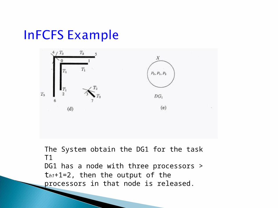
The System obtain the DG1 for the task T1DG1 has a node with three processors > th1+1=2, then the output of the processors in that node is released.

The System obtain the DG2 for the task T2DG2 has two node with different outputs.DGMM increase G2 by 1 ( add processors P1 to the group G2 )

System obtains the DG2 for the task T2. P3 disagree with more than ( th2 =1 ) neighboring processors, P3 conclude to be faulty.

System obtains the DG3 for the task T3. DGMM increase G3 by 1 (add processors P7 to the group G3)

System obtains the DG3 for the task T3.DGMM increase G3 by 1 (add processors P1 to the group G3)

System obtain the DG3 for the task T3DG3 has a node Z with three processors > th3, then the output of the processors in that node is released

When a task Ti,which may have more than one program version, arrives at the system, it is inserted along with their group sizes in the queue Q. When a task Ti is scheduled for execution, the DGMM algorithm is called to find the required group size for the task Ti.
• If the returned group size is equal to the required group
size, the first program version V1i of the task Ti is assigned to the group Gi for execution.

• If the returned group size by the DGMM algorithm is smaller than the required group size, then the returned group is allocated to the first program version V1j of the first task Tj in the task queue that fits the returned group. Next, the DGMM algorithm is called to find another subgraph of size gi in a different part of the system graph to allocate the task Ti
• If the DGMM returned the required group size, the first program version V1i of the task Ti is assigned to the group Gi for execution.

When a a task Ti version Vji completes its execution by all the processors in the group Gi, neighboring processors exchange and compare their outputs. Then, the disagreement graph DGi is obtained.
• If there is a disagreement between (thi + 1) processors on the outputs of first
version of Ti. The DGMM is called to increase group size of task Ti by one. gi = gi + 1. And the system execute the first version of Ti again.
• Else the next version of Ti is executed.

A task Ti is released if at least (thi + 1) different processors agree with each other on the output for at least (tsi +1) different program versions and the output for all the program versions are the same.
• When the task Ti finish its execution, the detected faulty components are deleted from the system.
• Otherwise, a task Ti is aborted for later execution

The features of the simulator
1. The computing environment is an M M torus system (M 1) connected to a host machine where scheduling and obtaining tasks disagreement graphs take place.
2. Each task (program) Ti which arrives at the system along with its reliability degree ti will be assigned to a group Gi of size gi (initially gi = ti + 1).
3. Tasks interarrival times are exponentially distributed with the average arrival rate .
4. Tasks mean execution times are exponentially distributed. Tasks arrived at the system could have different mean execution times.

In our simulation we consider a 6 x 6 torus system (M = 6).
We assume that there are long tasks and short tasks. Mean execution time of
long task is 10 time units and mean execution time of short task is 1 time unit.
we assume that there are three types of task hardware reliability degrees:
thi = 0 (type0), thi = 1 (type1) and thi = 2 (type2).
we assume that the task software reliability tsi = 1
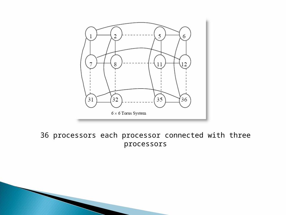
36 processors each processor connected with three processors
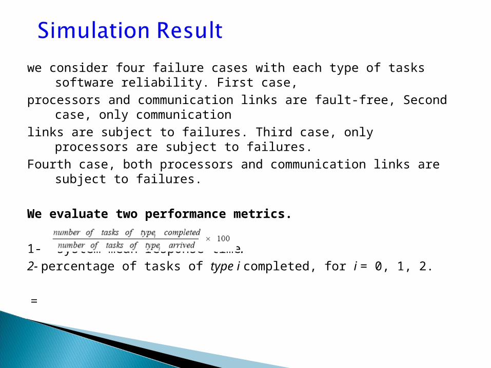
we consider four failure cases with each type of tasks software reliability. First case,
processors and communication links are fault-free, Second case, only communication
links are subject to failures. Third case, only processors are subject to failures.
Fourth case, both processors and communication links are subject to failures.
We evaluate two performance metrics.
1- system mean response time.
2- percentage of tasks of type i completed, for i = 0, 1, 2.
=

41

42
FCFS performance

43
FCFS performance
FCFS performance
In FCFS we can see from the plots as the task arrival rate λ increases, the average
response time also increases. Also, we can see as the task arrival rate λ increases, the
percentage of tasks completed of all tasks types decreases. Furthermore, the
percentage of tasks completed of all tasks types under each one of the failure cases is
almost the same. In other words, FCFS does not favor one type of task over another
type of task for execution.

45
FCFSSFF performance

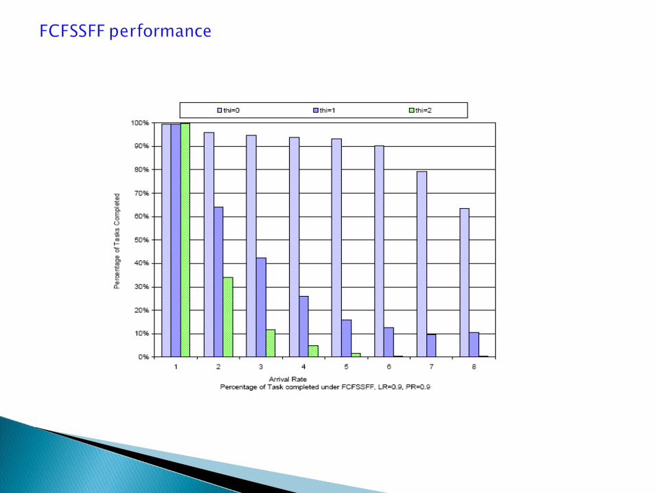

FCFS + Smallest Fit First PerformanceUnder the Integrated Fault-Tolerant First-Come, First-Served + Smallest Fits First
(FCFSSFF) scheduling algorithm, our simulation study showed that under the
conditions experimented here, beyond a point, as arrival rate λ increases, the system
average response time decreases. With a higher task arrival rate, the system average
response time increases. Also FCFSSFF scheduling algorithm favors tasks with small
group over tasks with large group for execution.

What is the goal of Integrated Fault Tolerant Techniques?
IFT attempts to maximize the system reliability and the system performance while concurrently diagnosing both hardware and software faults.