1- MOLTEN CARBONATE FUEL CELLS (MCFCs) - جامعة بابل · HIGH-TEMPERATURE FUEL CELLS ....
41
FUEL CELLS LECTURE NO. 5 Page 1 of 41 HIGH-TEMPERATURE FUEL CELLS 1- MOLTEN CARBONATE FUEL CELLS (MCFCs) The molten carbonate fuel cell operates at approximately 650 °C (1200 °F). The high operating temperature is needed to achieve sufficient conductivity of the carbonate electrolyte, yet allow the use of low-cost metal cell components. A benefit associated with this high temperature is that noble metal catalysts are not required for the cell electrochemical oxidation and reduction processes. Molten carbonate fuel cells are being developed for natural gas and coal-based power plants for industrial, electrical utility, and military applications (MCFCs operate more efficiently with CO2 containing bio-fuel derived gases. Performance loss on the anode due to fuel dilution is compensated by cathode side performance enhancement resulting from CO 2 enrichment.). Currently, one industrial corporation is actively pursuing the commercialization of MCFCs in the U.S.: Fuel Cell Energy (FCE). Europe and Japan each have at least one developer pursuing the technology: MTU Friedrichshafen, Ansaldo (Italy), and Ishikawajima-Harima Heavy Industries (Japan). Figure 1 depicts the operating configuration of the molten carbonate fuel cell. Figure 1: Principles of Operation of Molten Carbonate Fuel Cells.
Transcript of 1- MOLTEN CARBONATE FUEL CELLS (MCFCs) - جامعة بابل · HIGH-TEMPERATURE FUEL CELLS ....
FUEL CELLS LECTURE NO. 5
Page 1 of 41
HIGH-TEMPERATURE FUEL CELLS
1- MOLTEN CARBONATE FUEL CELLS (MCFCs)
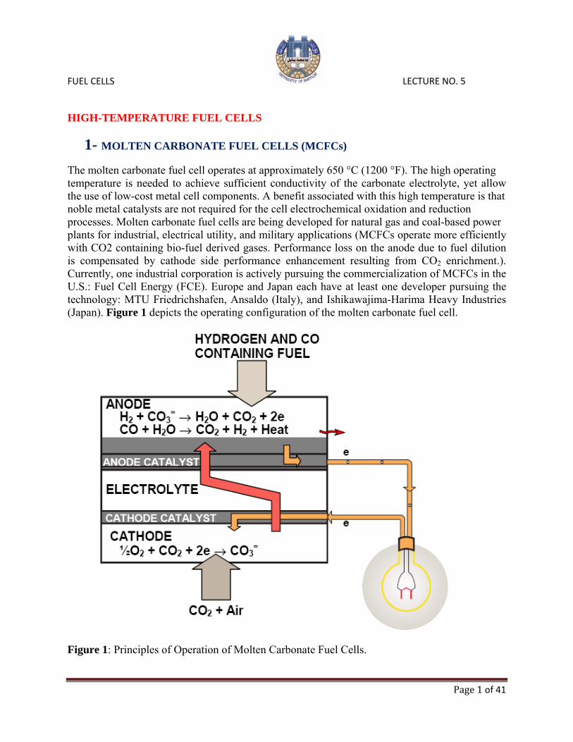
The molten carbonate fuel cell operates at approximately 650 °C (1200 °F). The high operating temperature is needed to achieve sufficient conductivity of the carbonate electrolyte, yet allow the use of low-cost metal cell components. A benefit associated with this high temperature is that noble metal catalysts are not required for the cell electrochemical oxidation and reduction processes. Molten carbonate fuel cells are being developed for natural gas and coal-based power plants for industrial, electrical utility, and military applications (MCFCs operate more efficiently with CO2 containing bio-fuel derived gases. Performance loss on the anode due to fuel dilution is compensated by cathode side performance enhancement resulting from CO2 enrichment.). Currently, one industrial corporation is actively pursuing the commercialization of MCFCs in the U.S.: Fuel Cell Energy (FCE). Europe and Japan each have at least one developer pursuing the technology: MTU Friedrichshafen, Ansaldo (Italy), and Ishikawajima-Harima Heavy Industries (Japan). Figure 1 depicts the operating configuration of the molten carbonate fuel cell.
Figure 1: Principles of Operation of Molten Carbonate Fuel Cells.
FUEL CELLS LECTURE NO. 5
Page 2 of 41
The half cell electrochemical reactions are: H2 + CO3
2- H2O + CO2 + 2e- at the anode, and ½O2 + CO2 + 2e- CO3
2- at the cathode
: H2 + ½O2 + CO2 (cathode) H2O + CO2 (anode) The overall cell reaction is
Note: CO is not directly used by electrochemical oxidation, but produces additional H2 when combined with water in the water gas shift reaction. The reversible potential for an MCFC, taking into account the transfer of CO2 from the cathode gas stream to the anode gas stream via the CO3
2-, is given by the equation:
where the subscripts a and c refer to the anode and cathode gas compartments, respectively. When the partial pressures of CO2 are identical at the anode and cathode, and the electrolyte is invariant, the cell potential depends only on the partial pressures of H2, O2, and H2O. Typically, the CO2 partial pressures are different in the two electrode compartments and the cell potential is affected accordingly. The need for CO2 at the cathode requires some schemes that will either:
1- transfer the CO2 from the anode exit gas to the cathode inlet gas ("CO2 transfer device") 2- produce CO2 by combusting the anode exhaust gas, which is mixed directly with the
cathode inlet gas, or 3- supply CO2 from an alternate source. It is usual practice in an MCFC system that the CO2
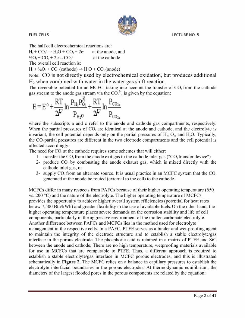
generated at the anode be routed (external to the cell) to the cathode. MCFCs differ in many respects from PAFCs because of their higher operating temperature (650 vs. 200 °C) and the nature of the electrolyte. The higher operating temperature of MCFCs provides the opportunity to achieve higher overall system efficiencies (potential for heat rates below 7,500 Btu/kWh) and greater flexibility in the use of available fuels. On the other hand, the higher operating temperature places severe demands on the corrosion stability and life of cell components, particularly in the aggressive environment of the molten carbonate electrolyte. Another difference between PAFCs and MCFCs lies in the method used for electrolyte management in the respective cells. In a PAFC, PTFE serves as a binder and wet-proofing agent to maintain the integrity of the electrode structure and to establish a stable electrolyte/gas interface in the porous electrode. The phosphoric acid is retained in a matrix of PTFE and SiC between the anode and cathode. There are no high temperature, wetproofing materials available for use in MCFCs that are comparable to PTFE. Thus, a different approach is required to establish a stable electrolyte/gas interface in MCFC porous electrodes, and this is illustrated schematically in Figure 2. The MCFC relies on a balance in capillary pressures to establish the electrolyte interfacial boundaries in the porous electrodes. At thermodynamic equilibrium, the diameters of the largest flooded pores in the porous components are related by the equation:
FUEL CELLS LECTURE NO. 5
Page 3 of 41
where γ is the interfacial surface tension, θ is the contact angle of the electrolyte, D is the pore diameter, and the subscripts a, c, and e refer to the anode, cathode and electrolyte matrix, respectively. By properly coordinating the pore diameters in the electrodes with those of the electrolyte matrix, which contains the smallest pores, the electrolyte distribution depicted in Figure 2 is established. This arrangement permits the electrolyte matrix to remain completely filled with molten carbonate, while the porous electrodes are partially filled, depending on their pore size distributions. According to the model illustrated in Figure 2 and described by the above equation, the electrolyte content in each of the porous components will be determined by the equilibrium pore size (<D>) in that component; pores smaller than <D> will be filled with electrolyte, and pores larger than <D> will remain empty. A reasonable estimate of the volume distribution of electrolyte in the various cell components is obtained from the measured pore-volume-distribution curves and the above relationship for D. Various processes (i.e., consumption by corrosion reactions, potential driven migration, creepage of salt and salt vaporization) occur, all of which contribute to the redistribution of molten carbonate in MCFCs.
Figure 2: Dynamic Equilibrium in Porous MCFC Cell Elements (Porous electrodes are depicted with pores covered by a thin film of electrolyte).

FUEL CELLS LECTURE NO. 5
Page 4 of 41
Cell Components The data in Table 1 provide a chronology of the evolution in MCFC component technology. Table 1: Evolution of Cell Component Technology for Molten Carbonate Fuel Cells.
a - Mole percent of alkali carbonate salt The conventional process to fabricate electrolyte structures until about 1980 involved hot pressing (about 5,000 psi) mixtures of LiAlO2 and alkali carbonates (typically >50 vol percent in liquid state) at temperatures slightly below the melting point of the carbonate salts (e.g., 490°C for electrolyte containing 62 mol Li2CO3 -38 mol K2CO3). These electrolyte structures (also called "electrolyte tiles") were relatively thick (1 to 2 mm) and difficult to produce in large sizes (The largest electrolyte tile produced by hot pressing was about 1.5 m2 in area) because large tooling and presses were required. The electrolyte structures produced by hot pressing are often characterized by:(1) void spaces (<5 porosity), (2) poor uniformity of microstructure, (3) generally poor mechanical strength, and (4) high iR drop. To overcome these shortcomings of hot pressed electrolyte structures, alternative processes such as tape casting and electrophoretic deposition for fabricating thin electrolyte structures were developed. The ohmic resistance of an electrolyte structure and the resulting ohmic polarization have a large influence on the operating voltage of MCFCs (making thinner electrolyte structures to improve cell performance).

FUEL CELLS LECTURE NO. 5
Page 5 of 41
The electrolyte composition affects the performance and endurance of MCFCs in several ways. Higher ionic conductivities, and hence lower ohmic polarization, are achieved with Li-rich electrolytes because of the relative high ionic conductivity of Li2CO3 compared to that of Na2CO3
and K2CO3. However, gas solubility and diffusivity are lower, and corrosion is more rapid in Li2CO3. The major considerations with Ni-based anodes and NiO cathodes are structural stability and NiO dissolution, respectively. Sintering and mechanical deformation of the porous Ni-based anode under compressive load lead to performance decay by redistribution of electrolyte in a MCFC stack. The dissolution of NiO in molten carbonate electrolyte became evident when thin electrolyte structures were used. Despite the low solubility of NiO in carbonate electrolytes (~10 ppm), Ni ions diffuse in the electrolyte towards the anode, and metallic Ni can precipitate in regions where a H2 reducing environment is encountered. The precipitation of Ni provides a sink for Ni ions, and thus promotes the diffusion of dissolved Ni from the cathode. This phenomenon becomes worse at high CO2 partial pressures because dissolution may involve the following mechanism: NiO + CO2 → Ni2+ + CO3
2- The dissolution of NiO has been correlated to the acid/base properties of the molten carbonate. The basicity of the molten carbonate is defined as equal to -log (activity of O2-) or -log aM2O, where a is the activity of the alkali metal oxide M2O. Based on this definition, acidic oxides are associated with carbonates (e.g., K2CO3) that do not dissociate to M2O, and basic oxides are formed with highly dissociated carbonate salts (e.g., Li2CO3). The solubility of NiO in binary carbonate melts shows a clear dependence on the acidity/basicity of the melt. In relatively acidic melts, NiO dissolution can be expressed by: NiO → Ni2+ + O2-
In basic melts, NiO reacts with O2- to produce one of two forms of nickelate ions:
NiO + O2- → NiO22-
2NiO + O2- + ½O2 → 2NiO2-
A distinct minimum in NiO solubility is observed in plots of log (NiO solubility) versus basicity (-log aM2O), which can be demarcated into two branches corresponding to acidic and basic dissolution. Acidic dissolution is represented by a straight line with a slope of +1, and a NiO solubility that decreases with an increase in aM2O. Basic dissolution is represented by a straight line with a slope of either -1 or -½, corresponding to the above two equations, respectively. The CO2 partial pressure is an important parameter in the dissolution of NiO in carbonate melts because the basicity is directly proportional to log PCO2. An MCFC usually operates with a molten carbonate electrolyte that is acidic. The solubility of NiO in molten carbonates is complicated by its dependence on several parameters: carbonate composition, H2O partial pressure, CO2 partial pressure, and temperature. The bipolar plates used in MCFC stacks are usually fabricated from thin (~15 mil) sheets of an alloy (e.g., Incoloy 825, 310S or 316L stainless steel) that are coated on one side (i.e., the side exposed to fuel gases in the anode compartment) with a Ni layer. The Ni layer is stable in the reducing gas environment of the anode compartment, and it provides a conductive surface coating with low contact resistance. Corrosion is largely overcome by applying a coating (about 50 µm thickness) at the vulnerable locations on the bipolar plate. For example, the wet-seal (the area of contact between the outer edge of the bipolar plate and the electrolyte structure prevents

FUEL CELLS LECTURE NO. 5
Page 6 of 41
gas from leaking out of the anode and cathode compartments. The gas seal is formed by compressing the contact area between the electrolyte structure and the bipolar plate so that the liquid film of molten carbonate at operating temperature does not allow gas to permeate through.) area on the anode side is subject to a high chemical potential gradient because of the fuel gas inside the cell and the ambient environment (usually air) on the outside of the cell, which promotes corrosion (about two orders of magnitude greater than in the cathode wet-seal area. A thin aluminum coating in the wet-seal area of a bipolar plate provides corrosion protection by forming a protective layer of LiAlO2 after reaction of Al with Li2CO3. Such a protective layer would not be useful in areas of the bipolar plate that must permit electronic conduction because LiAlO2 is an insulating material. A dense and electronically insulating layer of LiAlO2 is not suitable for providing corrosion resistance to the cell current collectors because these components must remain electrically conductive. The typical materials used for this application are 316 stainless steel and Ni plated stainless steels. However, materials with better corrosion resistance are required for long-term operation of MCFCs. Stainless steels such as Type 310 and 446 have demonstrated better corrosion resistance than Type 316 in corrosion tests. Development Components MCFC components are limited by several technical considerations: Anode: Anodes are made of a Ni-Cr/Ni-Al alloy. The Cr was added to eliminate the problem of anode sintering. However, Ni-Cr anodes are susceptible to creep when placed under the torque load required in the stack to minimize contact resistance between components. The Cr in the anode is also lithiated by the electrolyte; then it consumes carbonate. Developers are trying lesser amounts of Cr (8 percent) to reduce the loss of electrolyte, but some have found that reducing the Cr by 2 percentage points increased creep. Several developers have tested Ni-Al alloy anodes that provide creep resistance with minimum electrolyte loss. The low creep rate with this alloy is attributed to the formation of LiAlO2 dispersed in Ni. Even though alloys of chromium or aluminum strengthened nickel provides a stable, non-sintering, creep-resistant anode, electrodes made with Ni are relatively high in cost. Alloys, such as Cu-Al and LiFeO2, have not demonstrated sufficient creep strength or performance. Because of this, present research is focused on reducing the manufacturing cost of the nickel alloy anodes. There is a need for better sulfur tolerance in MCFCs, especially when considering coal operation. The potential benefit for sulfur tolerant cells is to eliminate cleanup equipment that impacts system efficiency. This is especially true if low temperature cleanup is required, because the system efficiency and capital cost suffer when the fuel gas temperature is first reduced, then increased to the cell temperature level. Tests are being conducted on ceramic anodes to alleviate the problems, including sulfur poisoning, being experienced with anodes. Anodes are being tested with undoped LiFeO2 and LiFeO2 doped with Mn and Nb. Preliminary testing, where several parameters were not strictly controlled, showed that the alternative electrodes exhibited poor performance and would not operate over 80 mA/cm2.

FUEL CELLS LECTURE NO. 5
Page 7 of 41
Cathode: An acceptable material for cathodes must have adequate electrical conductivity, structural strength, and low dissolution rate in molten alkali carbonates to avoid precipitation of metal in the electrolyte structure. Cathodes are made of lithiated NiO that have acceptable conductivity and structural strength. However, in early testing, a predecessor of UTC Fuel Cells found that the nickel dissolved, then precipitated and reformed as dendrites across the electrolyte matrix. This decreased performance and eventual short-circuiting of the cell. Dissolution of the cathode has turned out to be the primary life-limiting constraint of MCFCs, particularly in pressurized operation. Developers are investigating approaches to resolve the NiO dissolution issue. For atmospheric cells, developers are looking at increasing the basicity of the electrolyte (using a more basic melt such as Li/NaCO3). Another approach is to lower CO2 (acidic) partial pressure. To operate at higher pressures (higher CO2 partial pressure), developers are investigating alternative materials for the cathodes and using additives in the electrolyte to increase its basicity. Initial work on LiFeO2 cathodes showed that electrodes made with this material were very stable chemically under the cathode environment; there was essentially no dissolution. However, these electrodes perform poorly compared to the state-of-the-art NiO cathode at atmospheric pressure because of slow kinetics. The electrode shows promise at pressurized operation, so it is still being investigated. Higher performance improvements are expected with Co-doped LiFeO2. It also has been shown that 5 mol lithium-doped NiO with a thickness of 0.02 cm provided a 43 mV overpotential (higher performance) at 160 mA/cm2 compared to the state-of-the-art NiO cathode. It is assumed that reconfiguring the structure, such as decreasing the agglomerate size, could improve performance. Another idea for resolving the cathode dissolution problem is to formulate a milder cell environment. This leads to the approach of using additives in the electrolyte to increase its basicity. Small amounts of additives provide similar voltages to those without additives, but larger amounts adversely affect performance. Another approach to a milder cell environment is to increase the fraction of Li in the baseline electrolyte or change the electrolyte to Li/Na rather than the baseline 62/38 Li/K melt. Within the past 10 years, a lower cost stabilized cathode was developed with a base material cost comparable to the unstabilized cathode. A 100 cm2 cell test of the lower-cost stabilized cathode with a Li/Na electrolyte system completed 10,000 hours of operation. Electrolyte Matrix: The present electrolyte structure materials are tightly packed, fine α- or γ- LiAlO2 with fiber or particulate reinforcement. Long-term cell testing reveals significant particle growth and γ to α phase transformation, leading to detrimental changes in the pore structure. The particles grow faster at higher temperatures, in low CO2 gas atmospheres, and in strongly basic melts. The γ phase is stable at > 700 °C, whereas the α phase is stable at 600 to 650 °C. Such particle growth and phase transformations can be explained by a dissolution - precipitation mechanism. The matrix must also be strong enough to counter operating mechanical and thermal stresses, and still maintain the gas seal. Thermal cycling below the carbonate freezing temperature can induce cracking due to thermo-mechanical stress. Ceramic fiber reinforcement is most effective for crack deflection, followed by platelet and sphere forms. However, strong, cost effective, and stable ceramic fibers are not yet commercially available. Long-term, intense material research may be needed to develop such ceramic fibers. If particle sizes are markedly
FUEL CELLS LECTURE NO. 5
Page 8 of 41
different, the phase transformation is more controlled by the particle sizes, according to Ostwald ripening where small particles preferentially dissolve and re-precipitate onto larger particles. Therefore, a more uniform particle size distribution is needed to maintain a desired pore structure. The industry trend is to switch from γ -LiAlO2 to α -LiAlO2 for better long-term phase and particle-size stabilities. FCE is developing a low-cost LiAlO2, aqueous-base manufacturing system, but must resolve slow drying rate of LiAlO2 and its instability in water. Electrolyte: Present electrolytes have the following chemistry: lithium potassium carbonate, Li2CO3/K2CO3 (62:38 mol percent) for atmospheric pressure operation and lithium sodium carbonate, LiCO3/NaCO3 (52:48 o 60:40 mol percent) that is better for improved cathode stability under pressurized operation and life extension. The electrolyte composition affects electrochemical activity, corrosion, and electrolyte loss rate. Evaporation of the electrolyte is a life-limiting issue for the molten carbonate fuel cell. Li/Na electrolyte is better for higher pressure operation than Li/K because it gives higher performance. This allows the electrolyte matrix to be made thicker for the same performance relative to the Li/K electrolyte. Thicker electrolytes result in a longer time to shorting by internal precipitation. Li/Na also provides better corrosion resistance to mitigate acidic cathode dissolution. However, it has lower wettability and greater temperature sensitivity. Additives are being investigated to minimize the temperature sensitivity of Li/Na. The electrolyte has a low vapor pressure at operating temperature, and may slowly evaporate. Stack testing has shown that the electrolyte vapor loss is significantly slower than expected. The evaporation loss is projected to have minimal impact on stack life. Electrolyte Structure: Ohmic losses contribute about a 65 mV loss at the beginning of life, and may increase to as much as 145 mV by 40,000 hours. The majority of the voltage loss is in the electrolyte and the cathode components. The electrolyte offers the highest potential for reduction because 70 percent of the total cell ohmic loss occurs there. FCE investigated increasing the porosity of the electrolyte 5 percent to reduce the matrix resistance by 15 percent, and change the melt to Li/Na from Li/K to reduce the matrix resistivity by 40 percent. Work is continuing on the interaction of the electrolyte with the cathode components. At the present time, an electrolyte loss of 25 percent of the initial inventory can be projected with a low surface area cathode current collector and with the proper selection of material. Another area for electrolyte improvement is the ability to prevent gas crossover from one electrode to the other. FCE produced an improved matrix fabrication process providing low temperature binder burnout. Electrolyte Migration: There is a tendency for the electrolyte to migrate from the positive end of the stack to the negative end of the stack. This may cause the end cells to lose performance compared to the central cells. The electrolyte loss is through the gasket used to couple the external manifolds to the cell stack. The standard gasket material is porous and provides a conduit for electrolyte transfer. A new gasket design incorporating electrolyte flow barriers inside the gasket (US Patent 5,110,692) plus end cell inventory capability offers the potential for reaching 40,000 hours, if only this mode of failure is considered. Stacks with internal manifolding do not require a gasket, and may not experience this problem.
FUEL CELLS LECTURE NO. 5
Page 9 of 41
Bipolar Plate: The present bipolar plate consists of a separator, current collectors, and the wet seal. The separator and current collector is Ni-coated 310S/316L and the wet seal is formed by aluminization of the metal. The plate is exposed to the anode environment of one side and the cathode environment on the other. Low oxygen partial pressure on the anode side of the bipolar plate prevents the formation of a protective oxide coating. After reaction with the thin, creeping electrolyte, heat-resistant alloys form a multi-layered corrosion scale. This condition may be accelerated by carbonization, higher temperature, and higher moisture gas environment. On the cathode side, contact electrical resistance increases as an oxide scale builds up. Electrolyte loss due to corrosion and electrolyte creep also contributes to power decay. Single alloy bipolar current collector materials that function well in both anode and cathode environments need to be developed. Although such development has been attempted, high cost and high ohmic resistance prevent it from being successful. Presently, stainless steels, particularly austenitic stainless steels, are the primary construction materials. More expensive nickel-based alloys resist corrosion as well as or only slightly better than austenitic stainless steels. A thermodynamically stable nickel coating is needed to protect the anode side. Unfortunately, electroless nickel coatings, although dense or uniform in thickness, are expensive and contain detrimental impurities; electrolytic nickel coatings are not sufficiently dense or uniform in thickness. FCE and others have found that cladding with nickel provides excellent corrosion protection. A nickel cladding of 50 μm thickness is projected for >40,000 hours of life. Coal Gas Trace Species: MCFCs to date have been operated on reformed or simulated natural gas and simulated coal gas. Testing conducted with simulated coal gas has involved the expected individual and multi-trace constituents to better understand coal operation. Performance Factors affecting the selection of operating conditions are stack size, heat transfer rate, voltage level, load requirement, and cost. The performance curve is defined by cell pressure, temperature, gas composition, and utilization. Typical MCFCs will generally operate in the range of 100 to 200 mA/cm2
at 750 to 900 mV/cell.
1- Effect of Pressure The dependence of reversible cell potential on pressure is evident from the Nernst equation. For a change in pressure from P1 to P2, the change in reversible potential (∆Vp) is given by:
where the subscripts a and c refer to the anode and cathode, respectively. In an MCFC with the anode and cathode compartments at the same pressure (i.e., P1=P1,a=P1,c and P2=P2,a=P2,c):
FUEL CELLS LECTURE NO. 5
Page 10 of 41
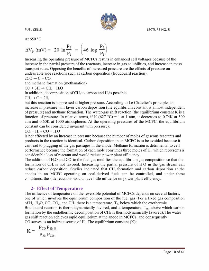
At 650 °C
Increasing the operating pressure of MCFCs results in enhanced cell voltages because of the increase in the partial pressure of the reactants, increase in gas solubilities, and increase in mass transport rates. Opposing the benefits of increased pressure are the effects of pressure on undesirable side reactions such as carbon deposition (Boudouard reaction): 2CO C + CO2
and methane formation (methanation) CO + 3H2 CH4 + H2O In addition, decomposition of CH4 to carbon and H2 is possible CH4 C + 2H2
but this reaction is suppressed at higher pressure. According to Le Chatelier’s principle, an increase in pressure will favor carbon deposition (the equilibrium constant is almost independent of pressure) and methane formation. The water-gas shift reaction (the equilibrium constant K is a function of pressure. In relative terms, if K (627 °C) = 1 at 1 atm, it decreases to 0.74K at 500 atm and 0.60K at 1000 atmospheres. At the operating pressures of the MCFC, the equilibrium constant can be considered invariant with pressure): CO2 + H2 CO + H2O is not affected by an increase in pressure because the number of moles of gaseous reactants and products in the reaction is identical. Carbon deposition in an MCFC is to be avoided because it can lead to plugging of the gas passages in the anode. Methane formation is detrimental to cell performance because the formation of each mole consumes three moles of H2, which represents a considerable loss of reactant and would reduce power plant efficiency. The addition of H2O and CO2 to the fuel gas modifies the equilibrium gas composition so that the formation of CH4 is not favored. Increasing the partial pressure of H2O in the gas stream can reduce carbon deposition. Studies indicated that CH4 formation and carbon deposition at the anodes in an MCFC operating on coal-derived fuels can be controlled, and under these conditions, the side reactions would have little influence on power plant efficiency.
2- Effect of Temperature The influence of temperature on the reversible potential of MCFCs depends on several factors, one of which involves the equilibrium composition of the fuel gas (For a fixed gas composition of H2, H2O, CO, CO2, and CH4 there is a temperature, Tb, below which the exothermic Boudouard reaction is thermodynamically favored, and a temperature, Tm, above which carbon formation by the endothermic decomposition of CH4 is thermodynamically favored). The water gas shift reaction achieves rapid equilibrium at the anode in MCFCs, and consequently CO serves as an indirect source of H2. The equilibrium constant (K):

FUEL CELLS LECTURE NO. 5
Page 11 of 41
increases with temperature , and the equilibrium composition changes with temperature and utilization to affect the cell voltage. The partial pressures of CO and H2O increase at higher T because of the dependence of K on T. The result of the change in gas composition, and the decrease in E° with increasing T, is that E decreases with an increase in T. In an operating cell, the polarization is lower at higher temperatures, and the net result is that a higher cell voltage is obtained at elevated temperatures (the polarization is reduced more significantly at the cathode with an increase in temperature, whereas the corresponding reduction in anode polarization is too small). With steam-reformed natural gas as the fuel and 30 percent CO2/70 percent air as the oxidant, the cell voltage at 200 mA/cm2
decreased by 1.4 mV/°C for a reduction in temperature from 650 to 600 °C, and 2.16 mV/°C for a decrease from 600 to 575 °C. In the temperature range 650 to 700 °C, data analysis indicates a relationship of 0.25 mV/°C. The following equations summarize these results:
The two major contributors responsible for the change in cell voltage with temperature are the ohmic polarization and electrode polarization. Most MCFC stacks currently operate at an average temperature of 650 °C. Most carbonates do not remain molten below 520 °C, and as seen by the previous equations, increasing temperature enhances cell performance. Beyond 650 °C, however, there are diminishing gains with increased temperature. In addition, there is increased electrolyte loss from evaporation and increased material corrosion. An operating temperature of 650 °C thus offers a compromise between high performance and stack life.
3- Effect of Reactant Gas Composition and Utilization The voltage of MCFCs varies with the composition of the reactant gases. The effect of reactant gas partial pressure, however, is somewhat difficult to analyze. One reason involves the water gas shift reaction at the anode due to the presence of CO. The other reason is related to the consumption of both CO2 and O2 at the cathode. Increasing the reactant gas utilization generally decreases cell performance. As reactant gases are consumed in an operating cell, the cell voltage decreases in response to the polarization (i.e., activation, concentration) and to the changing gas composition. These effects are related to the partial pressures of the reactant gases. Oxidant: The electrochemical reaction at the cathode involves the consumption of two moles CO2 per mole O2, and this ratio provides the optimum cathode performance. As the [CO2]/[O2]ratio decreases, the cathode performance decreases, and a limiting current is
FUEL CELLS LECTURE NO. 5
Page 12 of 41
discernible. In the limit where no CO2 is present in the oxidant feed, the equilibrium involving the dissociation of carbonate ions becomes important. CO3
2- CO2 + O2-
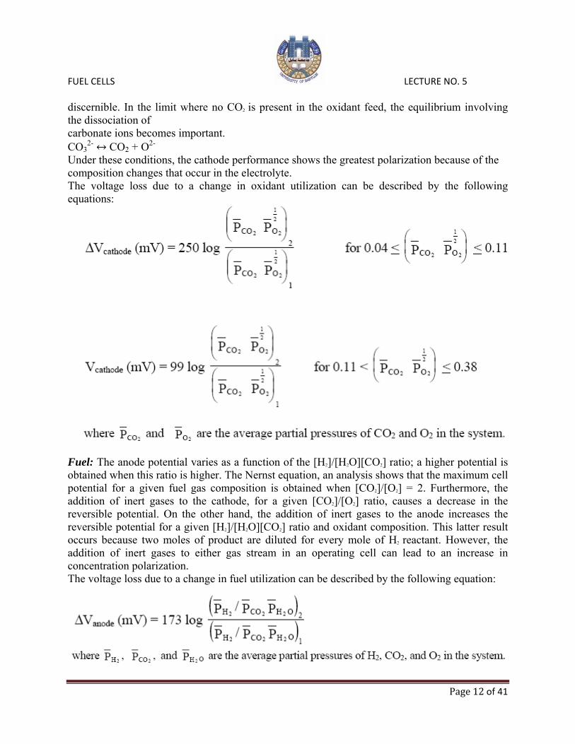
Under these conditions, the cathode performance shows the greatest polarization because of the composition changes that occur in the electrolyte. The voltage loss due to a change in oxidant utilization can be described by the following equations:
Fuel: The anode potential varies as a function of the [H2]/[H2O][CO2] ratio; a higher potential is obtained when this ratio is higher. The Nernst equation, an analysis shows that the maximum cell potential for a given fuel gas composition is obtained when [CO2]/[O2] = 2. Furthermore, the addition of inert gases to the cathode, for a given [CO2]/[O2] ratio, causes a decrease in the reversible potential. On the other hand, the addition of inert gases to the anode increases the reversible potential for a given [H2]/[H2O][CO2] ratio and oxidant composition. This latter result occurs because two moles of product are diluted for every mole of H2 reactant. However, the addition of inert gases to either gas stream in an operating cell can lead to an increase in concentration polarization. The voltage loss due to a change in fuel utilization can be described by the following equation:
FUEL CELLS LECTURE NO. 5
Page 13 of 41
The above discussion implies that MCFCs should be operated at low reactant gas utilizations to maintain voltage levels, but doing this means inefficient fuel use. As with other fuel cell types, a compromise must be made to optimize overall performance. Typical utilizations are 75 to 85% of the fuel.
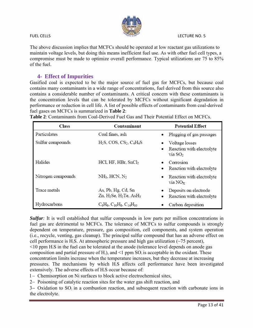
4- Effect of Impurities Gasified coal is expected to be the major source of fuel gas for MCFCs, but because coal contains many contaminants in a wide range of concentrations, fuel derived from this source also contains a considerable number of contaminants. A critical concern with these contaminants is the concentration levels that can be tolerated by MCFCs without significant degradation in performance or reduction in cell life. A list of possible effects of contaminants from coal-derived fuel gases on MCFCs is summarized in Table 2: Table 2: Contaminants from Coal-Derived Fuel Gas and Their Potential Effect on MCFCs.
Sulfur: It is well established that sulfur compounds in low parts per million concentrations in fuel gas are detrimental to MCFCs. The tolerance of MCFCs to sulfur compounds is strongly dependent on temperature, pressure, gas composition, cell components, and system operation (i.e., recycle, venting, gas cleanup). The principal sulfur compound that has an adverse effect on cell performance is H2S. At atmospheric pressure and high gas utilization (~75 percent), <10 ppm H2S in the fuel can be tolerated at the anode (tolerance level depends on anode gas composition and partial pressure of H2), and <1 ppm SO2 is acceptable in the oxidant. These concentration limits increase when the temperature increases, but they decrease at increasing pressures. The mechanisms by which H2S affects cell performance have been investigated extensively. The adverse effects of H2S occur because of: 1− Chemisorption on Ni surfaces to block active electrochemical sites, 2− Poisoning of catalytic reaction sites for the water gas shift reaction, and 3− Oxidation to SO2 in a combustion reaction, and subsequent reaction with carbonate ions in the electrolyte.

FUEL CELLS LECTURE NO. 5
Page 14 of 41
Low concentrations of H2S do not affect the open circuit potential, but they have a major impact on the cell voltage as current density is progressively increased. The decrease in cell voltage is not permanent;( The effects of H2S on cell voltage are reversible if H2S concentrations are present at levels below that required to form nickel sulfide.) when fuel gas without H2S is introduced into the cell, the cell voltage returns to the level for a cell with clean fuel. These results can be explained by the chemical and electrochemical reactions that occur involving H2S and S2-. A nickel anode at anodic potentials reacts with H2S to form nickel sulfide: H2S + CO H2O + CO2 + S2-
32-
Ni + xS2- iSx + 2xe-
followed by N
NiSx + xH2 Ni + xH2S When the sulfided anode returns to open circuit, the NiSx is reduced by H2:
Similarly, when a fuel gas without H2S is introduced to a sulfided anode, reduction of NiSx to Ni can also occur. The rapid equilibration of the water gas shift reaction in the anode compartment provides an indirect source of H2 by the reaction of CO and H2O. If H2S poisons the active sites for the shift reaction, this equilibrium might not be established in the cell, and a lower H2 content than predicted would be expected. Fortunately, evidence indicates that the shift reaction is not significantly poisoned by H2S. In fact, Cr used in stabilized-Ni anodes appears to act as a sulfur tolerant catalyst for the water gas shift reaction. The CO2 required for the cathode reaction is expected to be supplied by recycling the anode gas exhaust (after combustion of the residual H2) to the cathode. Therefore, any sulfur in the anode effluent will be present at the cathode inlet unless provisions are made for sulfur removal. In the absence of sulfur removal, sulfur enters the cathode inlet as SO2, which reacts quantitatively (equilibrium constant is 1015 to 1017) with carbonate ions to produce alkali sulfates. These sulfate ions are transported through the electrolyte structure to the anode during cell operation. At the anode, SO42- is reduced to S2-, thus increasing the concentration of S2-
there. Based on the present understanding of the effect of sulfur on MCFCs, and with the available cell components, it is projected that long-term operation (40,000 hr) of MCFCs may require fuel gases with sulfur (Both COS and CS2 appear to be equivalent to H2S in their effect on MCFCs)
levels of the order 0.01 ppm or less, unless the system is purged of sulfur at periodic intervals or sulfur is scrubbed from the cell burner loop. Considerable effort has been devoted to develop low-cost techniques for sulfur removal, and research and development are continuing. The effects of H2S on cell voltage are reversible if H2S concentrations are present at levels below which nickel sulfide forms. Halides: Halogen-containing compounds are destructive to MCFCs because they can lead to severe corrosion of cathode hardware. Thermodynamic calculations show that HCl and HF react with molten carbonates (Li2CO3 and K2CO3) to form CO2, H2O, and the respective alkali halides. Furthermore, the rate of electrolyte loss in the cell is expected to increase because of the high vapor pressure of LiCl and KCl. The concentration of Cl- species in coal-derived fuels is typically in the range 1 to 500 ppm. It has been suggested that the level of HCl should be kept below 1 ppm in the fuel gas, perhaps below 0.5 ppm, but the tolerable level for long-term operation has not been established.

FUEL CELLS LECTURE NO. 5
Page 15 of 41
Nitrogen Compounds: Compounds such as NH3 and HCN do not appear to harm MCFCs in small amounts. However, if NOX is produced by combustion of the anode effluent in the cell burner loop, it could react irreversibly with the electrolyte in the cathode compartment to form nitrate salts. The NH3 tolerance of MCFCs was 0.1 ppm, but it is indicated that the level could be 1 vol percent. Solid Particulates: These contaminants can originate from a variety of sources, and their presence is a major concern because they can block gas passages and/or the anode surface. Carbon deposition and conditions that can be used to control its formation have been discussed earlier in this section. Solid particles such as ZnO, which is used for sulfur removal, can be entrained in the fuel gas leaving the desulfurizer. The results indicate that the tolerance limit of MCFCs to particulates larger than 3 µm diameter is <0.1 g/l. Other Compounds: Experimental studies indicate that 1 ppm As from gaseous AsH3 in fuel gas does not affect cell performance, but when the level is increased to 9 ppm As, the cell voltage drops rapidly by about 120 mV at 160 mA/cm2. Trace metals, such as Pb, Cd, Hg, and Sn in the fuel gas, are of concern because they can deposit on the electrode surface or react with the electrolyte.
5- Effects of Current Density The voltage output from an MCFC is reduced by ohmic, activation, and concentration losses that increase with increasing current density. The major loss over the range of current densities of interest is the linear iR loss. The magnitude of this loss (iR) can be described by the following equations:
where J is the current density (mA/cm2) at which the cell is operating.
6- Effects of Cell Life Endurance of the cell stack is a critical issue in the commercialization of MCFCs. Adequate cell performance must be maintained over the desired length of service, quoted by one MCFC developer as being an average potential degradation no greater than 2mV/1,000 hours over a cell stack lifetime of 40,000 hours. State-of-the-art MCFCs depict an average degradation over time of:
FUEL CELLS LECTURE NO. 5
Page 16 of 41
7- Internal Reforming
In a conventional fuel cell system, a carbonaceous fuel is fed to a fuel processor where it is steam reformed to produce H2 (as well as other products, CO and CO2, for example), which is then introduced into the fuel cell and electrochemically oxidized. The internal reforming molten carbonate fuel cell, however, eliminates the need for a separate fuel processor for reforming carbonaceous fuels. This concept is practical in high-temperature fuel cells where the steam reforming reaction (Steam reforming of CH4 is typically performed at 750 to 900 °C; thus, at the lower operating temperature of MCFCs, a high activity catalyst is required. Methanol is also a suitable fuel for internal reforming. It does not require an additional catalyst because the Ni-based anode is sufficiently active) can be sustained with catalysts. By closely coupling the reforming reaction and the electrochemical oxidation reaction within the fuel cell, the concept of the internal reforming MCFC is realized. The internal reforming MCFC eliminates the need for the external fuel processor. It was recognized early that the internal reforming MCFC approach provides a highly efficient, simple, reliable, and cost effective alternative to the conventional MCFC system. There are two alternate approaches to internal reforming molten carbonate cells: indirect internal reforming (IIR) and direct internal reforming (DIR). In the first approach, the reformer section is separate, but adjacent to the fuel cell anode. This cell takes advantage of the close-coupled thermal benefit where the exothermic heat of the cell reaction can be used for the endothermic reforming reaction. Another advantage is that the reformer and the cell environments do not have a direct physical effect on each other. A disadvantage is that the conversion of methane to hydrogen is not promoted as well as in the direct approach. In the DIR cell, hydrogen consumption reduces its partial pressure, thus driving the methane reforming reaction CH4 + H2O CO + 3H2 to the right. Figure 3 depicts one developer's approach where IIR and DIR have been combined. The steam reforming reaction occurs simultaneously with the electrochemical oxidation of hydrogen in the anode compartment. The steam reforming reaction is endothermic, with ∆H650°C
= 53.87 kcal/mol, whereas the overall fuel cell reaction is exothermic. In an internal reforming MCFC, the heat required for the reaction is supplied by heat from the fuel cell reaction, thus eliminating the need for external heat exchange that is required by a conventional fuel processor. In addition, the product steam from the reaction can be used to enhance the reforming reaction and the water gas shift reaction to produce additional H2. The forward direction of the reforming reaction is favored by high temperature and low pressure; thus, an internal reforming MCFC is best suited to operate near atmospheric pressure. A supported Ni catalyst (e.g., Ni supported on MgO or LiAlO2) sustains the steam reforming reaction at 650 °C to produce sufficient H2 to meet the needs of the fuel cell.

FUEL CELLS LECTURE NO. 5
Page 17 of 41
Figure 3: IIR/DIR Operating Concept, Molten Carbonate Fuel Cell Design. Direct Internal Reforming Catalysts: The anode catalyst is deactivated by the alkali carbonate’s electrolyte-containing environment. Making hardware of a non-wetting metal such as nickel has mitigated electrolyte creepage over the hardware surface towards the catalyst. Presently DIR catalyst deactivation is mainly by the vapor phase alkali species. The deactivation mechanism includes electrolyte-accelerated sintering, pore filling/plugging, and surface coverage. Making hardware of a non-wetting metal such as nickel has mitigated electrolyte creepage over the hardware surface towards the catalyst. Alkali-resistant supports such as magnesium oxide, calcium aluminate, and α-alumina have been investigated to reduce vapor phase alkali species effects. Results show that these supports undergo different degrees of decay. Ruthenium and rhodium-based catalysts are more stable, but are too costly FCE has identified a more active and stable DIR catalyst (high activity supported Ni), projecting a catalyst life exceeding 40,000 hours and pursuing further enhancement of catalyst life. Another approach is to apply a getter-type barrier to trap the volatile alkali species before they reach the catalysts. A porous Ni or a SiC membrane was placed between the cell internal catalyst and the electrolyte-containing components.

FUEL CELLS LECTURE NO. 5
Page 18 of 41
2- SOLID OXIDE FUEL CELLS (SOFCs)
Solid oxide fuel cells have an electrolyte that is a solid, non-porous metal oxide, usually Y2O3-stablilized ZrO2. The cell operates at 600-1000 °C where ionic conduction by oxygen ions takes place. Typically, the anode is a Ni-ZrO2 cermet and the cathode is Sr-doped LaMnO3. There is no liquid electrolyte with its attendant material corrosion or electrolyte management problems. The high temperature of the SOFC, however, places stringent requirements on its materials. The development of suitable low cost materials and the low-cost fabrication of ceramic structures are presently the key technical challenges facing SOFCs. The cell is constructed with two porous electrodes that sandwich an electrolyte. Air flows along the cathode. When an oxygen molecule contacts the cathode/electrolyte interface, it acquires electrons from the cathode. The oxygen ions diffuse into the electrolyte material and migrate to the other side of the cell where they contact the anode. The oxygen ions encounter the fuel at the anode/electrolyte interface and react catalytically, giving off water, carbon dioxide, heat, and electrons. The electrons transport through the external circuit, providing electrical energy.
Solid oxide fuel cells (SOFC) allow conversion of a wide range of fuels, including various hydrocarbon fuels. The relatively high operating temperature allows for highly efficient conversion to power, internal reforming, and high quality by-product heat for cogeneration or for use in a bottoming cycle. Indeed, both simple-cycle and hybrid SOFC systems have demonstrated among the highest efficiencies of any power generation system, combined with minimal air pollutant emissions and low greenhouse gas emissions. These capabilities have made SOFC an attractive emerging technology for stationary power generation in the 2 kW to 100s MW capacity range.

FUEL CELLS LECTURE NO. 5
Page 19 of 41
More recently, (planar) SOFC systems with high power densities operating at lower temperatures (700 to 850 °C instead of 900 to 1000 °C as was previously the norm) have been developed. Combined with the ability of SOFC to use conventional fossil fuels, this could help reduce the cost of the fuel cell because less-expensive materials of construction could be used at lower temperatures. This would improve the economy of applications ranging from small-scale stationary power (down to ~2 kW) to auxiliary power units for vehicles and mobile generators for civilian as well as military applications. There is even the possibility that SOFC could eventually be used for part of the prime power in vehicles. The present challenge for developers is to produce robust, high-performance stack technologies based on suitable low-cost materials and fabrication methods. Derivatives from SOFC technology, such as oxygen sensors used in automobiles, are already in widespread commercial use.
Cell Components The major components of an individual SOFC cell include the electrolyte, the cathode, and the anode. Fuel cell stacks contain an electrical interconnect, which links individual cells together in series or parallel. The electrolyte is made from a ceramic such as yttria-stabilized zirconia (YSZ) and functions as a conductor of oxide ions. Oxygen atoms are reduced into oxide ions on the porous cathode surface by electrons, and then flow through the ceramic electrolyte to the fuel-rich porous anode where the oxide ions react with fuel (hydrogen), giving up electrons. The interconnect serves to conduct the electrons through an external circuit.
Electrolyte Materials SOFCs use solid oxide ceramics, typically perovskites, as the electrolyte. Currently, yttrium stablilized zirconia (3, 8, or 10 percent yttria, abbreviated to YSZ) is the most commonly used electrolyte for SOFC. YSZ provides high conductivity at temperatures above 700 °C, while exhibiting negligible electronic conductivity at these temperatures (above 1500 °C it becomes an electronic conductor). In a fuel cell operating with a current density of 250 mA/cm2 at 1000 °C and an electrolyte of 200 µm thickness, the resistance loss in the electrolyte would be 50 mV. However, for mechanical reasons it is desirable to operate the SOFC at lower temperatures. To operate at 800 °C, the electrolyte thickness would have to be reduced by about an order of magnitude to maintain a similar ohmic loss in the electrolyte. Colloidal fabrication and co-sintering processes have emerged, whereby YSZ membranes are produced as thin films (~10 µm) on porous electrode structures. These thin-film membranes improve performance and reduce operating temperatures of SOFCs. To enable these colloidal processes to be successful, finer YSZ powders are needed. These applications require nano-scale powders with BET surface areas of 100 to 120 m2/g and the use of suspensions ranging from 10 to 40 percent solid content. Scandium-doped zirconia (SDZ) is more conductive than YSZ, permitting a further reduction of the operating temperature by 50 to 100 °C. Gadolinium-doped ceria is even more conductive, but is partially reduced in hydrogen at temperatures above 600 °C; formation of Ce3+ ions generates electron holes that make ceria electronically conductive, thus short-circuiting the cell. All of the above-mentioned solid electrolytes are oxygen conductors. An automatic consequence of this is that, as in molten carbonate fuel cells, the products of electrochemical reactions all end up on the anode side. While is beneficial for internal reforming and water gas shift reaction

FUEL CELLS LECTURE NO. 5
Page 20 of 41
(which utilizes the water produced as a reactant), it dilutes the fuel, and at high utilization it can significantly reduce the Nernst potential. Solid electrolytes can be made to conduct protons. While these electrolytes are still in a very early stage of development, such proton conductors might eventually overcome some of the limitations of cells as oxygen ion conductors. Anode Materials Although a wide range of materials has been considered as anode materials for SOFC, most developers today use a cermet of nickel and YSZ. The composition of the anode, particle sizes of the powders, and the manufacturing method are key to achieving high electrical conductivity, adequate ionic conductivity, and high activity for electrochemical reactions and reforming and shift reactions. Reduction of the NiO powder in the virgin anode mixture to Ni results in the desired porosity. For the more recent anode-supported cells, it also achieves good mechanical properties and maintains geometric stability during manufacture and operation. Using a combination of coarse and fine YSZ powder, mechanical strength can be ensured while also achieving the desired contact between the Ni phase and the YSZ phase. In some modern cell designs, a graded anode is used to achieve coarse porosity and high mechanical strength in most of the anode, and fine micro-porosity in the anode zone immediately adjacent to the electrolyte. Despite the relative success of the Ni-YSZ anode, it has drawbacks:
1- Sensitivity to sulfur and other contaminants. Strong reversible poisoning of the anode occurs at feed concentrations ranging from about 1 ppm H2S when operating at 1000 °C down to less than 50 ppb when operating at 750 °C . These concentrations require desulfurization of the anode feed, even if it is produced from low-sulfur fuels such as natural gas or ultra-low sulfur diesel or gasoline. Another strong anode poison reported is HCl. Poisoning by these species is reversible after exposure at low concentrations, but irreversible after exposure at concentrations above about 200 ppm.
2- Oxidation reduction intolerance. Ni-YSZ anodes are made by mixing NiO with YSZ and then reducing the NiO to Ni. However, if the anode is subsequently exposed to air, especially at elevated temperatures, the Ni re-oxidizes readily. Because of the large volume change during the reduction/oxidation of the anode, the anode’s structure and strength are severely compromised. Effectively, the anodes must be kept under reducing conditions at all times.
3- The thermal expansion coefficient of the anode is substantially higher than the electrolyte and cathode. In anode-supported designs, this can lead to mechanical and dimensional stability problems, especially during thermal cycling.
4- Poor activity for direct oxidation of hydrocarbons and propensity for carbon formation when exposed to hydrocarbons. To improve the activity for direct oxidation and reduce the anode’s propensity for carbon formation, copper – ceria anodes are being developed.
The oxide-based anodes provide excellent oxidation/reduction stability. In addition, they can be used to improve the sulfur tolerance and reduction oxidation tolerance of the anodes.

FUEL CELLS LECTURE NO. 5
Page 21 of 41
Cathode Materials Most cathode materials used in SOFC today are lanthanum-based perovskite materials (structure ABO3). Most cathodes are based on doped lanthanum manganites. In high temperature SOFC (operating temperature ~1000 °C), strontium-doped LaMnO3 (LSM) is used. The choice of this material is a compromise between a number of factors:
1- Chemical stability and relatively low interactions with electrolyte. With YSZ electrodes, many La-based compounds form the insulating La2Zr2O7. With ceria-based electrolytes, this issue is not a concern and other cathode materials are considered (e.g. (La,Sr)(Co,Fe)O3 or LSCF).
2- Adequate electronic and ionic conductivity. Though the conductivities are adequate, the ionic conductivity of LSM is significantly lower than YSZ, and its electronic conductivity is a fraction of any of the metals or even of lanthanum chromite. Consequently, ionic and electronic resistance can become a significant factor, especially in cell designs that incorporate long current paths through the cathode. For lower-temperature cells, conductivity of LSM is inadequate, and other materials, such as strontium-doped lanthanum ferrite (LSF) are considered.
3- Relatively high activity. 4- Manageable interactions with ceramic interconnects (notably lanthanum chromite).
Though some interdiffusion occurs, this does not represent a major problem. 5− Thermal expansion coefficients that closely match those of YSZ.
The good compatibility with YSZ and the high electro-catalytic activity make LSM the cathode material of choice of SOFCs operating around 1000 °C. For intermediate-temperature operation (700 to 800 °C), a composite layer (typically 20 to 40 µm thick) of YSZ and LSM is often used to overcome the modest ion conductivity at lower temperatures. Alternatively, LSCF or LSF are also pursued for such applications. A serious challenge in the use of LSM as a cathode material in intermediate temperature SOFC stems from the use of metallic interconnects. Many of these metals contain chromium, which forms a stable protective oxide (chromia) layer with reasonable conductivity. However, chromia vapors can lead to serious poisoning of the cathode. Although one might attribute this problem more to the interconnect material than to the cathode, the poisoning effect was found to depend strongly on the electrolyte/cathode material combination. For low-temperature operation (below 700 °C), the use of LSM as the cathode material represents significant potential loss, and other materials are being pursued. Interconnect Materials Broadly, interconnect materials for SOFC fall into two categories: conductive ceramic (perovskite) materials for operation at high temperature (900 to 1000 °C) and metallic alloys for lower temperature operation. Though the shape of SOFC interconnects depends heavily on the cell and stack design, the materials choice is almost entirely determined by physical and chemical stability under operating conditions. The ceramic interconnects used in higher temperature SOFCs are primarily doped lanthanum and yttrium chromites (dopants typically include Mg, Sr, Ca, Ca/Co). These perovskites are unique in

FUEL CELLS LECTURE NO. 5
Page 22 of 41
that they exhibit high electronic conductivity and resist reduction under exposure to syngas at high temperatures. Electronic conductivity of these materials increases with temperature (making them unsuitable for use at low temperatures). At 1,000 °C the conductivities of these materials range from 1 to around 30 S/cm, with an activation energy of 12 to 19 kJ/mol, depending on dopant and dopant level. The dopant levels also control thermo-mechanical properties and compatibility with electrode or electrolyte materials. Lanthanum chromite-based interconnects have shown to be stable in cells for as much as 69,000 hrs. However, one problem with ceramic interconnects is that they are rigid and weak, similar to the ceramic cells: there is no flexibility in any of the components to ensure good contact pressure. In some designs that use ceramic interconnects, a contact felt or conductive contact paste is used. Unfortunately, the reliability of this component is not as good as the interconnect. With the development of thin-electrolyte anode-supported SOFC operation at lower temperatures (lower than 800 °C), the prospect of using metallic interconnects arose. However, even at temperatures ranging from 650 to 800 °C, typical state-of-the-art anode-supported SOFC operating conditions and design requirements for metallic interconnects are challenging. For example:
• High operating temperature in excess of the drop-off in creep strength for many common metals and thermal cycling. At the same time, the interconnect must maintain uniform contact (usually requiring some pressure) with the electrodes.
• Exposure (at least on one side) to strongly oxidizing environment, while at the same time requiring low contact resistance with the electrodes. This is a challenge because many of the stable oxides that protect high-temperature alloys from corrosion such as alumina and silica) have very low conductivities. The most commonly-used stable oxide that does have some electronic conductivity (chromia) leads to evaporation and electrode poisoning.
Lower operating temperatures would allow the use of ferritic steels, that could reduce the materials cost, and ferritic steels are typically easier to process with low-cost processing techniques. The corrosion resistance of steel depends on the formation of stable oxide layers on the surface. After extensive testing of commercial compositions, it was concluded that none possessed the corrosion resistance required, especially to withstand the thermal cycling requirements while still providing adequate contact resistance. To ensure good contact resistance (primarily with the cathode) and minimize evaporation of chromia, many developers use interconnect coatings of strontium-doped lanthanum cobaltite or manganite, which have proven effective for at least several thousand hours. With these improvements, interconnects can be made that function in intermediate temperature SOFCs, although several additional improvements may still require attention to allow the construction of commercially viable products:
1- Further improvement in contact resistance and in corrosion resistance, especially after long exposure and thermal cycling
2- Improved performance and mechanical stability of the coatings 3- Low-cost manufacturing methods for materials, shapes, and coatings 4- Improved creep strength to increase design flexibility for cells.

FUEL CELLS LECTURE NO. 5
Page 23 of 41
SOFC anodes are fabricated from composite powdered mixtures of electrolyte materials (YSZ, GDC, or SDC) and nickel oxide. The nickel oxide is subsequently reduced to nickel metal prior to operation. The NiO/YSZ anode material is suited for applications with YSZ material, whereas NiO/SDC and NiO/GDC anode materials are best used with ceria-based electrolyte materials. Typical anode materials have nickel content of approximately 40 volume percent after reduction of the nickel oxide to nickel. Depending upon the application, powders have surface areas of 15 to 20 m2/g for screen-printing and 5 to 10 m2/g for tape casting. Seal Materials The challenges of sealing the oxidant from fuel in planar SOFC stacks is significant, hence a sub-section is devoted to potential seal materials here. The function of SOFC seals includes:
1- Prevent mixing of fuel and oxidant 2- In some configurations, prevent mixing of reactants with the ambient environment 3- In some configurations, provide mechanical bonding of components 4- In some designs, provide electrical insulation between stack components
Seal materials must be chemically and physically stable at operating conditions. In some applications (e.g. in on-road vehicles), the seal must also be able to withstand acceleration forces associated with vibration and shock. Finally, seal materials must be low in cost and amenable to low-cost stack manufacturing methods. These requirements are tough to meet simultaneously. For example, the chemical stability of a material may be acceptable under either oxidizing or reducing environments. However, mechanistic characterizations have shown that when relatively thin pieces of material are exposed to both atmospheres, rapid deterioration occurs. Seal designs are highly specific to particular cell and stack designs and, consequently, seal designs are often proprietary. Some tubular and monolithic designs require no seals at all. Planar designs typically require multiple seals per repeat unit, and even in planar designs the length of the seals can vary by two or three orders of magnitude for a given area cell depending on design. The requirements, material choices, and general sealing concepts are common to most planar SOFC stack designs. Fundamentally, two different types of seals are being developed for SOFC: bonded and compressive seals. Bonded Seals Bonded seals can be rigid or compliant. A hermetic seal is achieved through adhesive forces between the seal material and both surfaces against which the seal is to work. Naturally, the seal material must have good adhesive properties (good wettability of the material to be sealed). Some are designed to remain flexible over the operating range of the cell, while others are meant to be rigid. To use the rigid type of seal, the thermal expansion coefficient of the seal material and all other components must be closely matched. If the seal is compliant, the thermal expansion coefficient matching requirements are somewhat relaxed. The bonding temperature for this type of seal should lie between the operating temperature and the stability limit for the other cell materials. There are several common sub-types of bonded seals currently under consideration for SOFC applications. Glass and glass-ceramic seals are perhaps the most common.

FUEL CELLS LECTURE NO. 5
Page 24 of 41
This type of seal is attractive because:
1- Viscous/wetting behavior of glass facilitates hermetic sealing 2- They are inexpensive and easy to manufacture and apply 3- Wide range of compositions of glass and ceramics allows tailoring some of the key
properties (e.g. thermal expansion coefficient glass transition temperature) 4- Glass-ceramics can be designed to avoid viscous flow and uncontrolled progressive
crystallization during operation However, glass-ceramic seals also exhibit disadvantages:
1- They are brittle, leading to seal and even cell failures during cool-down; 2- Despite control, few glass systems allow a match of thermal expansion coefficient to
other important cell materials (typically alkaline earth-alumina-silica glasses). In any case, the cell materials don’t match each other close enough to allow a rigid seal in larger cells
3- Many glasses interact with adjacent cell components, especially with the interconnects 4- Some of the constituents of glass volatilize during operation (e.g. silica, borate, and alkali
metals). These constituents will likely foul or poison the electrode catalyst or interact in an undesirable manner with other cell components.
Metal brazes, which use a molten metal filler to ensure sealing, provide some attractive features:
1- Molten metal facilitates hermetic sealing 2- Easy to fabricate 3- Properties can be tailored by judicious choice of composition
However, several factors limit their application in SOFC:
• Brazes are electrically conductive, making them unsuitable of most seal types • Few braze materials are compatible with SOFC operating conditions. Noble metals are
considered too expensive in most SOFC stack designs. Silver is less expensive, but its use in a dual (oxidizing and reducing) environment can lead to chemical instability In addition to the benefits listed above, bonded seals result in compact structures, as no load-frame or other means to apply pressure is required. However, in cells with metal interconnects, the mismatch in thermal expansion may be too great for the use of rigid seals. Compressive Seals A hermetic seal is achieved by pressing the seal material between the surfaces to be sealed. The seal material must be elastic over the operating temperature range, and sufficiently soft to fill the micro-roughness on the surfaces to be sealed. Compressive seals offer several advantages:
1- Mechanically “de-couple” adjacent stack components, thus reducing thermal stress during cycling
2- Thermal expansion matching requirements between cell components may be somewhat relaxed (though electrical contact considerations may still require this)
3- Some are easy and inexpensive to fabricate

FUEL CELLS LECTURE NO. 5
Page 25 of 41
However, there are also barriers to overcome:
1- Difficult to achieve a hermetic seal with some materials unless “soft seat” interlayer is provided
2- Few materials and structures are compliant and provide a hermetic seal at the operating temperatures
3- A load frame is required to provide compression to all seals. This type of hardware is potentially bulky and expensive. If (portions of the) load frame must be kept at lower temperatures than the stack itself, packaging and insulation is significantly complicated, especially if multiple stacks are to be combined for larger-capacity systems
4- Other stack components must be designed to withstand prolonged pressure. This can be a challenge, given that creep strength of the metals used in the interconnect is typically very low (in the 700 to 800 °C operating temperature range typical for state-of-the-art planar cells)
5- To the extent that electrical contact between cell components depends on controlled pressure, balancing these pressure requirements with those of the seal can be a challenge for the cell designer.
Recently, mica and hybrid mica seals have been developed as a viable technology. Mica seals were found to have many desirable characteristics, such as the ability to withstand thermal cycling, but exhibited unacceptable leak rates. When a thin layer of glass is inserted on either side of the seal to fill the voids between the seal and the other stack components, the leak rate was substantially reduced while other desirable properties were retained.
FUEL CELLS LECTURE NO. 5
Page 26 of 41
Cell and Stack Designs Two types of cell designs are being pursued for SOFC: tubular cells and planar cells. The interest in tubular cells is unique to SOFC: all other types of fuel cells focus exclusively on planar designs. In SOFC, the benefit of a simple sealing arrangement potentially outweighs the disadvantages of low volumetric power density and long current path that are inherent in tubular cell geometries.
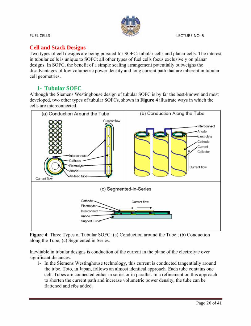
1- Tubular SOFC Although the Siemens Westinghouse design of tubular SOFC is by far the best-known and most developed, two other types of tubular SOFCs, shown in Figure 4 illustrate ways in which the cells are interconnected.
Figure 4: Three Types of Tubular SOFC: (a) Conduction around the Tube ; (b) Conduction along the Tube; (c) Segmented in Series. Inevitable in tubular designs is conduction of the current in the plane of the electrolyte over significant distances:
1- In the Siemens Westinghouse technology, this current is conducted tangentially around the tube. Toto, in Japan, follows an almost identical approach. Each tube contains one cell. Tubes are connected either in series or in parallel. In a refinement on this approach to shorten the current path and increase volumetric power density, the tube can be flattened and ribs added.

FUEL CELLS LECTURE NO. 5
Page 27 of 41
2- In micro-tubular SOFC technology (e.g. Acumentrics), current is conducted axially along
the tube. Interconnections are made at the end of the tube using various proprietary interconnection systems that connect cells within the stack. To minimize the in-plane resistance on the cathode side, a metallic current collector (typically silver) is applied.
3- In segmented-in-series tubular SOFC technology, the tube’s active cell area is segmented and connected in series. As a consequence, the length over which in-plane conduction occurs can be controlled by the cell segmentation pattern. Another consequence of segmentation in series is that the voltage per tube is higher, and hence the total current lower, requiring less heavy-duty interconnections between tubes.
Tubular SOFC Cell Manufacturing Method A schematic cross-section of the Siemens Westinghouse cell is shown in Figure 5. Air is fed through an alumina feed tube, while fuel is supplied externally. The cell length has been gradually increased from 30 cm to about 150 cm. The cell has a diameter of 1.27 cm.
Figure 5: Schematic cross-section of cylindrical Siemens Westinghouse SOFC Tube. To ensure good contact between tubes, nickel felt is used. Because the current flows tangentially to the electrodes, a relatively large ohmic loss exists, especially in the cathode, which places an upper limit on the tube diameter. To make a tubular SOFC, the cathode tube is fabricated first by extrusion and sintering. As shown in Table 3, it has a porosity of 30 to 40 percent to permit rapid transport of reactant and product gases to the cathode/electrolyte interface where the electrochemical reactions occur. The electrolyte is applied to the cathode tubes by electrochemical vapor deposition (EVD), which for many years has been the heart of Siemens Westinghouse technology. In this technique, metal

FUEL CELLS LECTURE NO. 5
Page 28 of 41
chloride vapor is introduced on one side of the tube surface, and O2/H2O is introduced on the other side. The gas environments on both sides of the tube act to form two galvanic couples, as described in equations:
The net result is the formation of a dense, uniform metal oxide layer in which the deposition rate is controlled by the diffusion rate of ionic species and the concentration of electronic charge carriers. This procedure is used to fabricate the solid YSZ electrolyte. The anode consists of metallic Ni and YSZ. The latter inhibits sintering of the metal particles, with thermal expansion comparable to the other cell materials. The anode structure is fabricated with a porosity of 20-40 percent to facilitate mass transport of reactant and product gases. Table 3: Evolution of Cell Component Technology for Tubular Solid Oxide Fuel Cells.
a - Specification for Siemens Westinghouse SOFC b - Y2O3 stabilized ZrO2
c - “Fixed EVD” means additional ZrO2 is grown by EVD to fix (attach) the nickel anode to the electrolyte. This process is expected to be replaced. d - EVD = electrochemical vapor deposition
FUEL CELLS LECTURE NO. 5
Page 29 of 41
The cell interconnect (doped lanthanum chromite) must be impervious to fuel and oxidant gases, and must possess good electronic conductivity. The interconnect is exposed to both the cathode and anode environments. Thus, it must be chemically stable under O2 partial pressures of about 1 to 10-18 atmospheres at 1,000 °C. The interconnect material is applied to the cathode tube as a narrow strip (see Figure 5) prior to depositing the electrolyte by masking the rest of the tube. Similarly, the interconnect strip is masked when the electrolyte is applied. The other cell components should permit only electronic conduction, and inter-diffusion of ionic species in these components at 1,000 °C should not affect their electronic conductivity. Other restrictions on the cell components are that they must be stable in the gaseous environments in the cell and they must be capable of withstanding thermal cycling. The resistivities of typical cell components at 1,000 °C under fuel cell gaseous environments are 10 ohm-cm (ionic) for the electrolyte (8-10 mol percent Y2O3 doped ZrO2), 1 ohm-cm (electronic) for the cell interconnect (doped LaCrO3), 0.01 ohm-cm (electronic) for the cathode (doped LaMnO3), and 3 x 10⁻⁶ ohm-cm (electronic) for the anode (Ni/ZrO2cermet). It is apparent that the solid oxide electrolyte is the least conductive of the cell components, followed by the cell interconnect. Furthermore, an operating temperature of about 1,000 °C is necessary if the ionic conductivity of the solid electrolyte (i.e., 0.02/ohm-cm at 800 °C and 0.1/ohm-cm at 1,000 °C) is to be within an order of magnitude of that of aqueous electrolytes. The solid electrolyte in SOFCs must be only about 25 to 50 µm thick if its ohmic loss at 1,000 °C is to be comparable to the electrolyte in PAFCs. Fortunately, thin electrolyte structures of about 40 µm thickness can be fabricated by EVD, as well as by tape casting and other ceramic processing techniques. Operation of SOFCs requires individual cell components that are thermally compatible so that stable interfaces are established at 1,000 °C, i.e., CTEs for cell components must be closely matched to reduce thermal stress arising from differential expansion between components. An anode made of 100 percent nickel would have excellent electrical conductivity. However, the CTE of 100 percent nickel would be 50 percent greater than the ceramic electrolyte and the cathode tube, which causes a thermal mismatch. This thermal mismatch has been resolved by mixing ceramic powders with Ni or NiO. The trade-off in the amounts of Ni (to achieve high conductivity) and ceramic (to better match the CTE) is approximately 30/70 Ni/YSZ by volume. Schematic representations of the gas manifold design and cross section of a typical tube bundle are presented in Figure 6. In this design, the tubular cathode is formed by extrusion. The electrolyte and cell interconnect are deposited by electrochemical vapor deposition (EVD) and plasma spraying, respectively, on the cathode. The anode is subsequently formed on the electrolyte by slurry deposition. A major advantage of this design is that relatively large single tubular cells can be constructed in which the successive active layers can be deposited without chemical or material interference with previously-deposited layers. The support tube is closed at one end, which eliminates gas seals between cells. The oxidant is introduced via a central A12O3 injector tube and fuel gas is supplied to the exterior of the closed-end cathode tube. In this arrangement, the A12O3 tube extends to the closed end of the tube, and the oxidant flows back past the cathode surface to the open end. The fuel flows past the anode on the exterior of the cell and in a parallel direction (co-flow) to the oxidant gas. The spent gases are exhausted into a common plenum, where any remaining fuel reacts. The heat generated preheats the incoming oxidant stream and drives an expander.

FUEL CELLS LECTURE NO. 5
Page 30 of 41
One attractive feature of this arrangement is that it eliminates the need for leak-free gas manifolding of the fuel and oxidant streams. However, the seal-less tubular design results in a relatively long current path around the circumference of the cell.
Figure 6: Gas Manifold Design for a Tubular SOFC and Cell-to-Cell Connections in a Tubular SOFC (a bundle of eighteen cells that features 3 cells in series with 6 cells in parallel). For the current YSZ electrolyte to provide sufficient oxygen conductivity, it must be heated to a high temperature (900 to 1,000 °C). This means that expensive, high temperature alloys must be used to house the fuel cell, increasing its cost substantially. These costs could be reduced if the operating temperature was lowered to between 600 to 800 °C, allowing the use of less expensive structural materials such as stainless steel. A lower operating temperature would also ensure a

FUEL CELLS LECTURE NO. 5
Page 31 of 41
greater overall system efficiency and a reduction in the thermal stress in the ceramic structure, leading to a longer service life for the fuel cell. To lower the operating temperature, either the conductivity of the YSZ must be improved by thinner electrolytes, or alternative electrolytic materials must be developed that can replace YSZ. A concerted effort is being made by researchers around the world to find a better solution. Performance This section provides empirical information that can be used to estimate the performance of SOFCs based on various operating parameters. The SOFCs being developed, particularly the planar types, have unique designs, are constructed of various materials, and are fabricated by different techniques. This development process will result in further evolution of the performa e trends summarized here. The electrochemical reactions associated with hydrogen fuel are e ressed in equations:
ncx
H2 + O2- 2O + 2e- at the anode, and p H
½O2 + 2e- O2- at the cathode
H2 + ½O2 H2O , the corresponding Nernst equation for this reaction is: The overall cell reaction is:
In addition to hydrogen, carbon monoxide (CO) and other hydrocarbons such as methane (CH4) can be used as fuels. It is feasible that the water gas shift reaction involving CO : CO + H2O 2 + CO2 H
CH4 + H2O 3H2 + CO and the steam reforming of CH4:
in the high temperature environment of SOFCs produce H2 that is easily oxidized at the anode. The direct oxidation of CO in fuel cells is also well established. Because of the increased number of chemical species and competing reactions, however, derivation of cell performance as a function of temperature, pressure, and composition effects is not straightforward. The thermodynamic efficiency of SOFCs operating on H2 and O2 at open circuit voltage is lower than that of MCFCs and PAFCs because of the lower free energy at higher temperatures. On the other hand, the higher operating temperature of SOFCs is beneficial in reducing polarization resistance. The voltage losses in SOFCs are governed by ohmic losses in the cell components. The contribution to ohmic polarization (iR) in a tubular cell (assuming uniform current distribution in the electrolyte) is 45 percent from the cathode, 18 percent from the anode, 12 percent from the electrolyte, and 25 percent from the interconnect when these components have thicknesses of 2.2, 0.1, 0.04 and 0.085 mm, respectively, and specific resistivities (ohm-cm) at 1,000 °C of 0.013, 3 x 10⁻⁶, 10, and 1, respectively. The cathode iR dominates the total ohmic loss despite the higher specific resistivities of the electrolyte and cell interconnection because of the short conduction path through these components and the long current path in the plane of the cathode.
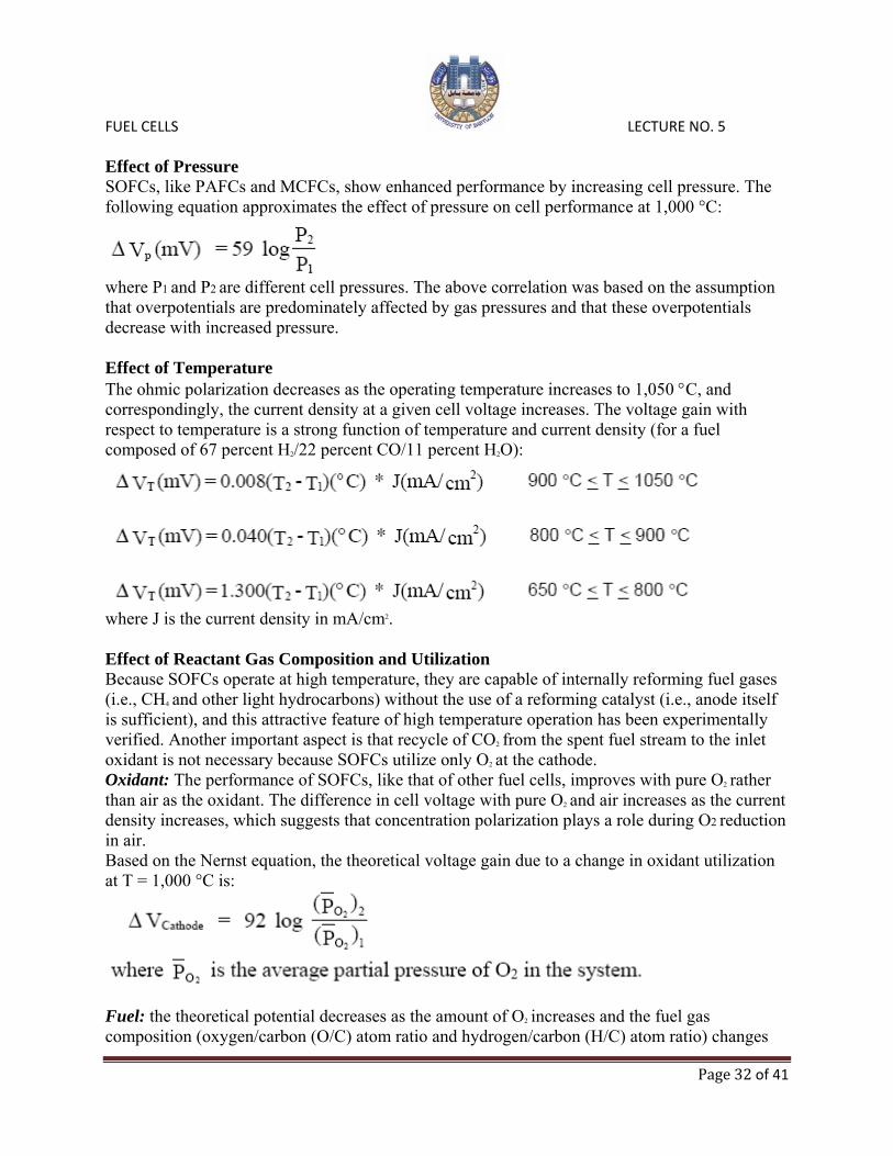
FUEL CELLS LECTURE NO. 5
Page 32 of 41
Effect of Pressure SOFCs, like PAFCs and MCFCs, show enhanced performance by increasing cell pressure. The following equation approximates the effect of pressure on cell performance at 1,000 °C:
where P1 and P2 are different cell pressures. The above correlation was based on the assumption that overpotentials are predominately affected by gas pressures and that these overpotentials decrease with increased pressure. Effect of Temperature The ohmic polarization decreases as the operating temperature increases to 1,050 °C, and correspondingly, the current density at a given cell voltage increases. The voltage gain with respect to temperature is a strong function of temperature and current density (for a fuel composed of 67 percent H2/22 percent CO/11 percent H2O):
where J is the current density in mA/cm2. Effect of Reactant Gas Composition and Utilization Because SOFCs operate at high temperature, they are capable of internally reforming fuel gases (i.e., CH4 and other light hydrocarbons) without the use of a reforming catalyst (i.e., anode itself is sufficient), and this attractive feature of high temperature operation has been experimentally verified. Another important aspect is that recycle of CO2 from the spent fuel stream to the inlet oxidant is not necessary because SOFCs utilize only O2 at the cathode. Oxidant: The performance of SOFCs, like that of other fuel cells, improves with pure O2 rather than air as the oxidant. The difference in cell voltage with pure O2 and air increases as the current density increases, which suggests that concentration polarization plays a role during O2 reduction in air. Based on the Nernst equation, the theoretical voltage gain due to a change in oxidant utilization at T = 1,000 °C is:
Fuel: the theoretical potential decreases as the amount of O2 increases and the fuel gas composition (oxygen/carbon (O/C) atom ratio and hydrogen/carbon (H/C) atom ratio) changes

FUEL CELLS LECTURE NO. 5
Page 33 of 41
from CO to CO2. The presence of hydrogen in the fuel produces two results: (1) the potential is higher, and (2) the O/C ratio corresponding to complete oxidation extends to higher values. These effects occur because the equilibrium composition obtained by the water gas shift reaction in gases containing hydrogen (H2O) and carbon (CO) produces H2, but this reaction is not favored at higher temperatures. In addition, the theoretical potential for the H2/O2 reaction exceeds that for the CO/O2 reaction at temperatures of about 800 °C. Consequently, the addition of hydrogen to the fuel gas will yield a higher open circuit potential in SOFCs. Based on the Nernst equation, the theoretical voltage gain due to a change in fuel utilization at T = 1,000 °C is:
Effect of Impurities Hydrogen sulfide (H2S), hydrogen chloride (HCl) and ammonia (NH3) are impurities typically found in coal gas. Some of these substances may harm the performance of SOFCs. Early experiments used a simulated oxygen-blown coal gas containing 37.2 percent CO/34.1 percent H2/0.3 percent CH4 /14.4 percent CO2/13.2 percent H2O/0.8 percent N2. These experiments showed no degradation in the presence of 5,000 ppm NH3. An impurity level of 1 ppm HCl also showed no detectable degradation. H2S levels of 1 ppm resulted in an immediate performance drop, but this loss soon stabilized into a normal linear degradation. Additional experiments showed that removing H2S from the fuel stream returned the cell to nearly its original level. It was also found that maintaining an impurity level of 5,000 ppm NH3
and 1 ppm HCl, but decreasing the H2S level to 0.1 ppm eliminated any detrimental effect due to the presence of sulfur, even though, as mentioned above, 1 ppm H2S caused virtually no degradation. Silicon (Si), which also can be found in coal gas, has been studied as a contaminant. It is believed to accumulate on the fuel electrode in the form of silica (SiO2). The deposition of Si throughout the cell has been found to be enhanced by high (~50%) H2O content in the fuel. Si is transported by the f owing reaction: ollSiO2 (s) + 2H2O (g) Si(OH)4 (g) As CH4 reforms to CO and H2, H2O is consumed. This favors the reversal of this reaction, which allows SiO2 to be deposited downstream, possibly on exposed nickel surfaces. Oxygen-blown coal gas, however, has a H2O content of only ~13 percent, and this is not expected to allow for significant Si transport. Effect of Current Density The voltage level of a SOFC is reduced by ohmic, activation, and concentration losses, which increase with increasing current density. The magnitude of this loss is described by the following equation:
where J is the current density (mA/cm2) at which the cell is operating.

FUEL CELLS LECTURE NO. 5
Page 34 of 41
Effect of Cell Life The endurance of the cell stack is of primary concern for SOFCs. As SOFC technology has continued to approach commercialization, research in this area has increased and improvements made. The Siemens Westinghouse state-of-the-art tubular design has been validated by continuous electrical testing of over 69,000 hours with less than 0.5 percent voltage degradation per 1,000 hours of operation. This tubular design is based on the early calcia-stabilized zirconia porous support tube (PST). In the current technology, the PST has been eliminated and replaced by a doped lanthanum manganite air electrode tube. These air electrode-supported (AES) cells have shown a power density increase of approximately 33 percent over the previous design. Siemens Westinghouse AES cells have shown less than 0.2 % voltage degradation per 1,000 hours in a 25 kW stack operated for over 44,000 hours, and negligible degradation in the 100 kW stack operated in the Netherlands and Germany (>16,000 hours).
2- Planar SOFC A variety of planar SOFC sub-types are distinguished according to construction: Structural support for membrane/electrolyte assembly:
1- Electrolyte-supported. Early planar cells were mostly electrolyte-supported. This requires a relatively thick electrolyte (>100 but typically around 200 µm, with both electrodes at about 50 µm) which leads to high resistance, requiring high-temperature operation. Sulzer Hexis and Mitsubishi Heavy Industries (MHI) are actively pursuing this technology and have scaled-up the technology into 1 and 15 kW systems, respectively. Power density at 0.7 V is reported to be about 140 mW/cm2 for the Sulzer stacks and about 190 to 220 mW/cm2 for the MHI stacks, both under commercially-relevant operating conditions.
2- Cathode-supported. This allows for a thinner electrolyte than electrolyte-supported cells, but mass transport limitations (high concentration polarization) and manufacturing challenges (it is difficult to achieve full density in a YSZ electrolyte without over-sintering an LSM cathode) make this approach inferior to anode-supported thin-electrolyte cells.
3- Anode-Supported. Advances in manufacturing techniques have allowed the production of anode-supported cells (supporting anode of 0.5 to 1 mm thick) with thin electrolytes. Electrolyte thicknesses for such cells typically range from around 3 to 15 µm (thermomechanically, the limit in thickness is about 20 to 30 µm (the cathode remains around 50 µm thick), given the difference in thermal expansion between the anode and the electrolyte). Such cells provide potential for very high power densities (up to 1.8 W/cm2 under laboratory conditions, and about 600 to 800 mW/cm2 under commercially-relevant conditions).
4- Metal interconnect-supported. Lawrence Berkeley National Laboratory, Argonne National Laboratory, and Ceres have pioneered metal-supported cells to minimize mass transfer resistance and the use of (expensive) ceramic materials. In such cells, the electrodes are typically 50 µm thick and the electrolyte around 5 to15 µm. While the benefits are obvious, the challenges are to find a materials combination and manufacturing process that avoids corrosion and deformation of the metal and interfacial reactions during manufacturing as well as operation.

FUEL CELLS LECTURE NO. 5
Page 35 of 41
Interconnect material:
• Ceramic (lanthanum or yttrium chromite) suitable for high-temperature operation (900 to 1000 °C). These materials, while chemically stable and compatible with the MEA from a chemical and thermal expansion perspective, are mechanically weak and costly.
• Cr-based or Ni-based superalloy for intermediate-high temperature operation (800 to 900 °C). These materials are chemically stable at 900 °C, but they require additional coatings to prevent Cr-poisoning of the electrodes. In addition, they are expensive and difficult to form.
• Ferritic steel (coated or uncoated) for intermediate temperature operation (650 to 800 °C). While uncoated steels are chemically unstable, especially during thermal cycling, coated steels provide corrosion resistance as well as acceptable conductivity when new. However, thermal cycling performance still requires improvement.
Shape of the cell.
• Rectangular, with gases flowing in co-flow, counter-flow, or cross-flow. • Circular, typically with gases flowing out from the center in co-flow, and mixing and
burning at the edge of the cells. Spiral flow arrangements and counter-flow arrangements have also been proposed.
Method for creating flow-channels:
• Flat ceramic cell with channels in interconnect or flow-plate. • Corrugated ceramic with flat interconnects.
Manifolding arrangement:
• External manifolding. • Internal manifolding, through the electrolyte. • Internal manifolding through the interconnect, but not through the electrolyte.
Figure 7 shows a sample of recently-pursued planar SOFC approaches. The anode-supported technology with metal interconnects will be described in some detail below. Mitsubishi tested a 15 kW system with its all-ceramic MOLB design for almost 10,000 hours with degradation rates below 0.5 percent per 1,000 hrs, but without thermal cycles, and with power densities ranging from 190 to 220 mW/cm2 (under practical operating conditions). Because the interconnect is flat and relatively thin (the flow-passage is embedded in the MEA), less of the expensive LaCrO3 is required than if the flow-passages were in the interconnect. Nevertheless, cost reduction is still one of the main priorities for this stack technology. Thermal cycling is also thought to be a challenge with the system, which is targeted to small-scale distributed stationary power generation applications. Sulzer Hexis built 110 1 kW demonstration units based on its electrolyte-supported technology with superalloy interconnects. The latest version of the units, integrated into a hot water/heating appliance, has shown a degradation rate of around 1 to 2 percent per 1000 hrs in continuous operation, and about 2x higher with thermal cycling.

FUEL CELLS LECTURE NO. 5
Page 36 of 41
Figure 7: Overview of Types of Planar SOFC: (a) Planar Anode-Supported SOFC with Metal Interconnects; (b) Electrolyte-Supported Planar SOFC Technology with Metal Interconnect; (c) Electrolyte-Supported Design with “egg-crate” electrolyte shape and ceramic interconnect. The planar anode-supported SOFC with metal interconnects has benefited from support for fundamental science and stack development under the U.S. Department of Energy’s Solid State Energy Conversion Alliance (DOE’s SECA) Program. The SECA Program is focused on developing technology required for competitive SOFC stack technologies that can be mass-customized for a wide range of applications, including stationary power generation, mobile power generation, military power applications, and transportation applications such as auxiliary power units (APUs). By commercializing SOFC stacks for a number of applications simultaneously, stack production could be increased more rapidly and, consequently, manufacturing cost reduced more quickly. The SECA Program has two interrelated components: (1) the core program in which universities, national laboratories, and private industry develop fundamental component and materials technologies for SOFC stacks that can be licensed with stack developers, and (2) a vertical program with teams of private stack developers with other parties to develop and demonstrate stacks that meet the SECA goals. Particularly useful, and broadly shared amongst the international SOFC development community, are the stack performance goals developed by SECA. Over the past ten years, this technology has developed from a scientific concept to cell

FUEL CELLS LECTURE NO. 5
Page 37 of 41
technologies that can achieve 1.8 W/cm2 under idealized laboratory conditions, and stacks that can achieve initial power densities of 300 to 500 mW/cm2. The power density of this technology has allowed the engineering of integrated systems for small-scale stationary power and APU applications, making the hypothesis that these stack technologies can be customized for a wide range of high-volume applications. Single Cell Performance A significant advance in the development of intermediate temperature PSOFCs has been the use of metallic “bipolar” interconnects in conjunction with thin electrolytes. Although originally conceptualized in the early 1990s, development of the anode-supported planar SOFC with metallic interconnects was significantly accelerated by the US DOE’s SECA Program. The benefits of the anode-supported approach with metallic interconnects were readily recognized (see summary in Table 4):
• Sintering and Creep – Milder temperatures result in less sintering and creep of the stack materials. This helps maintain geometric stability and high surface area for reaction.
• Thermally Activated Processes – Thermally activated processes such as chromium vaporization, elemental inter-diffusion and migration, metallic corrosion, and ceramic aging become problematic at higher temperatures. The lower the operating temperature is maintained, the less damage these processes will cause to the fuel cell.
• Thermal Stress – Reduced width of the operating temperature band reduces thermal expansion and contraction stresses during cycling, thus maintaining geometric stability.
• Increase in Nernst potential. • Heat Loss – Reduced heat loss from the more compact stack at lower operating
temperature. • Material Flexibility – The range of potential construction materials is somewhat greater at
lower temperatures. In particular, certain metals can be incorporated in SOFC stack designs.
• Balance of Plant (BOP) – The BOP costs may be less if lower cost materials can be used in the recuperators. In addition, the stack temperatures will be closer to typical reformer and sulfur removal reactor operating temperatures; this further reduces the load on the thermal management system. However, it must be remembered that the main factor driving the heat duty of the thermal management system is the amount of cooling air required for stable stack operation, which in turn depends on the internal reforming capability of the stack and on the acceptable temperature rise across the stack.
• Start-up time may be reduced. Lighter weight and high thermal conductivity of the metal interconnects may allow more rapid heat-up to operating temperature.
Some negative effects also result from reducing the operating temperature of the SOFC: • A proven interconnect material for operating in the intermediate temperature range (650
to 800 oC) does not yet exist. • Sulfur resistance decreases with temperature. However, recent work has shown that
addition of certain materials provides adequate sulfur tolerance at lower temperatures.

FUEL CELLS LECTURE NO. 5
Page 38 of 41
• Lower temperatures generally require a planar configuration to minimize resistance
losses. This is accomplished using ultra-thin electrode and electrolyte membranes. In turn, effective seals for the planar configuration are needed.
Table 4: Recent Technology Advances on Planar Cells and Potential Benefits.
An example of a stack geometry is shown in Figure7-a. The cassette-type repeat unit with a plain rectangular ceramic cell, a metal picture frame with cavities for manifolding, and a matching separator plate is not uncommon among developers of planar anode-supported SOFC with metal interconnects. Units such as the one shown typically result in a pitch of 5 to 10 unit cells per inch. The bipolar plate has several functions, including providing a gas barrier between the anode and cathode, providing a series electrical connector between the anode and cathode, and flow field distribution. Individual cell assemblies, each including an anode, electrolyte, and cathode are stacked with metal interconnecting plates between them. The metal plates are shaped to permit the flow of fuel and air to the membranes. The electrolyte and interconnect layers are made by tape casting. The electrodes are applied by the slurry method, by screen-printing, by plasma spraying, or by tape-casting/tape calendaring. Fuel cell stacks are formed by layers of unit cells, much like other fuel cell technologies. To reduce resistivity of the electrolyte, development has focused on reducing its thickness from 150 µm to about 10 µm.
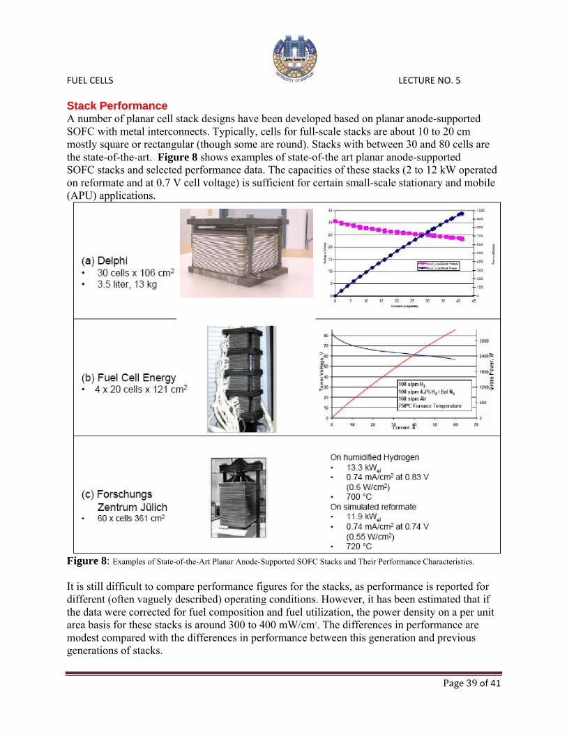
FUEL CELLS LECTURE NO. 5
Page 39 of 41
Stack Performance A number of planar cell stack designs have been developed based on planar anode-supported SOFC with metal interconnects. Typically, cells for full-scale stacks are about 10 to 20 cm mostly square or rectangular (though some are round). Stacks with between 30 and 80 cells are the state-of-the-art. Figure 8 shows examples of state-of-the art planar anode-supported SOFC stacks and selected performance data. The capacities of these stacks (2 to 12 kW operated on reformate and at 0.7 V cell voltage) is sufficient for certain small-scale stationary and mobile (APU) applications.
Figure 8: Examples of State-of-the-Art Planar Anode-Supported SOFC Stacks and Their Performance Characteristics. It is still difficult to compare performance figures for the stacks, as performance is reported for different (often vaguely described) operating conditions. However, it has been estimated that if the data were corrected for fuel composition and fuel utilization, the power density on a per unit area basis for these stacks is around 300 to 400 mW/cm2. The differences in performance are modest compared with the differences in performance between this generation and previous generations of stacks.

FUEL CELLS LECTURE NO. 5
Page 40 of 41
These three stack technologies can be considered to be among the most advanced of the planar anode-supported SOFC stacks. Interestingly, their stack architectures are rather similar:
• All are rectangular cells, with a cassette-type multi-component repeat unit design • All use integrated manifolds that do not pierce the ceramics • All use some form of stack compression, although presumably the Jülich stack requires
this for contact, not sealing (a glass seal is used). The longest operating experience is currently around 6,000 to 7,000 hours per stack. The effect of thermal cycling varies strongly from system to system, but it appears that about 5 to 10 thermal cycles are achievable. The effects of more thermal cycles combined with long-term operation are not well-characterized in the public literature. With respect to degradation rate, both chromia poisoning and interfacial resistances are issues that require further improvement. Because of the thin metal foils used in some of the designs, the effect of changes in chromium content of the bulk foil metal over long periods of time must be taken into account, and could influence corrosion behavior in a non-linear fashion. Stack Scale-Up Although some SOFC applications require systems no larger than the 2 to 10 kW to which many tubular and planar SOFC have been scaled-up, most stationary applications, especially those with the greatest potential impact on global energy use, will require systems ranging from about 200 kW for medium-scale distributed generation to several hundred MW for utility-scale power stations. Tubular SOFC systems have been scaled-up and integrated into systems with capacities up to 250 kW . This is accomplished by combining individual tubes into 3x8 tube modules with capacities of around 2 kW. These modules, in turn, are combined to form the stack. Mitsubishi Heavy Industries scaled-up its tubular segmented-in-series system to 10 kW (pressurized and atmospheric) and its all-ceramic planar design up to 15 kW. The planar design follows a scale-up approach that involves small ~2 kW units which are combined into larger stack units. Planar anode-supported stacks with metallic interconnects have been scaled-up to about 12 kW in a single stack. The question then arises how these stack technologies could be used to create systems with capacities ranging from 200 kW to at least 20 MW. One approach would be to simply combine ~5 kW stacks in a modular fashion into a larger system. However, as recent studies have implied, this would lead to rather complex manifolding arrangements of very large numbers of cells (a 1MW system would require at least 200 5 kW stacks). Although feasible, the complexity, cost, and pressure loss associated with such massive modularization are not trivial. Scaling up cells and individual single stacks may have limits based on fundamental considerations:
1- The larger the cells, the more severe the effects of CTE mismatches. 2- As cells are scaled up, pressure drop will increase unless flow channels are made
higher. Higher flow-channels will increase the cell resistance and, in most designs, increase the material intensity of the stack.
3- Scaling up the cells for certain applications makes it more difficult to mass-customize stack technology for a broad range of applications with different capacity requirements.
4- Increasing the number of cells has its limits because of mechanical stability concerns.
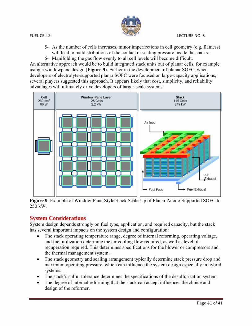
FUEL CELLS LECTURE NO. 5
Page 41 of 41
5- As the number of cells increases, minor imperfections in cell geometry (e.g. flatness)
will lead to maldistributions of the contact or sealing pressure inside the stacks. 6- Manifolding the gas flow evenly to all cell levels will become difficult.
An alternative approach would be to build integrated stack units out of planar cells, for example using a windowpane design (Figure 9). Earlier in the development of planar SOFC, when developers of electrolyte-supported planar SOFC were focused on large-capacity applications, several players suggested this approach. It appears likely that cost, simplicity, and reliability advantages will ultimately drive developers of larger-scale systems.
Figure 9: Example of Window-Pane-Style Stack Scale-Up of Planar Anode-Supported SOFC to 250 kW. System Considerations System design depends strongly on fuel type, application, and required capacity, but the stack has several important impacts on the system design and configuration:
• The stack operating temperature range, degree of internal reforming, operating voltage, and fuel utilization determine the air cooling flow required, as well as level of recuperation required. This determines specifications for the blower or compressors and the thermal management system.
• The stack geometry and sealing arrangement typically determine stack pressure drop and maximum operating pressure, which can influence the system design especially in hybrid systems.
• The stack’s sulfur tolerance determines the specifications of the desulfurization system. • The degree of internal reforming that the stack can accept influences the choice and
design of the reformer.


![Molten Carbonate Fuel Cells for SAGD - CESAR · [6] R. Remick and D. Wheeler, "Molten Carbonate and PhosphoricAcid Stationary Fuel Cells: Overview and Gap Analysis," National Renewable](https://static.fdocuments.in/doc/165x107/5e61d8083724b648a77118f9/molten-carbonate-fuel-cells-for-sagd-cesar-6-r-remick-and-d-wheeler-molten.jpg)