1 MIRI in a nutshell Bart Vandenbussche KU Leuven MIRI team meeting Leuven, 20 june 2013.
44
1 MIRI in a nutshell Bart Vandenbussche KU Leuven MIRI team meeting Leuven, 20 june 2013
-
Upload
agatha-cori-jackson -
Category
Documents
-
view
231 -
download
0
Transcript of 1 MIRI in a nutshell Bart Vandenbussche KU Leuven MIRI team meeting Leuven, 20 june 2013.

1
MIRI in a nutshell
Bart Vandenbussche
KU Leuven MIRI team meeting
Leuven, 20 june 2013

2

JWST elements
3
Integrated Science Instrument Module (ISIM) - Located inside an OTE provided ISIM Enclosure
- Contains 4 Science Instruments (NIRCam, NIRSpec MIRI, FGS / TF)
ISIM Electronics Compartment (IEC)
Spacecraft Bus- Contains traditional “ambient” subsystems
Solar Array
Thermal Region 2- Components maintained at
ambient temperatures on cold
side of the observatory
Thermal Region 1- Components cooled
to cryogenic temperatures
Thermal Region 3 - Components maintained at ambient temperatures
Sunshield (SS)- 5 layers to provide thermal
shielding to allow OTE and ISIM to passively cool to required
cryogenic temperatures
SS Layer 5
SS Layer 1
MomentumTrim-Tab
Optical Telescope Element (OTE)- 6 meter Tri-Mirror Anastigmatic - 18 Segment Primary Mirror
OTE Backplane/ ISIM Enclosure
OTE DeploymentTower
OTE SecondaryMirror
OTE Primary Mirror
Aft Optics Subsystem

STOWED / DEPLOYED configuration
4
21.197 m
10.661 m
6.600 m
6.100 m
14.625 m
Deployed Configuration
Stowed Configuration
4.472 m

JWST in the Ariane 5 fairing
5
D
XLV
-0.4
-0.3
-0.2
-0.1
0
0.1
0.2
0.3
0.4
-0.4 -0.3 -0.2 -0.1 0 0.1 0.2 0.3 0.4
Launcher Y axis (m)
Lau
nch
er Z
axi
s (m
)
Allowable for JWST per CNES 4/08
Tolerance Request
25° clocking angle
(-0.138m,-0.015m)
(-0.042m,-0.069m)
(-0.100m,-0.096m)
(-0.138m,-0.015m)
(-0.105m, 0.140m) (0.115m, 0.140m)
(0.115m, -0.085m)
(-0.105m, -0.085m)

JWST space and ground segment
6
L2 Transfer Trajectory
Ariane 5 UpperStage Injects JWSTInto Direct Transfer
Trajectory
S-Band Tlm Link ( 2Kbps)S-Band Ranging
S-Band Tlm Link ( 2Kbps)S-Band Cmd Link (0.25 Kbps)
S-Band Ranging
Observatory – Upper StageSeparation
Observatory Deployments- Solar Array
- High Gain/ Medium Antennas- Sunshield
- Optical Telescope Element
Communications Coverage ProvidedFor all Critical Events
Deep Space Network
Space Telescope Science InstituteScience & Operations Center
GSFC Flight Dynamics Facility
Ariane 5Launch System
NASA Integrated Services Network
Ariane PPF S5
CommunicationsServices for Launch
(TDRS, ESA, …)
L2 Point
L2 Lissajous Orbit
One 4 Hour Contact with the Ground Every 12 HoursKa-Band Science Link ( Selectable 7, 14, 28 Mbps)
S-Band Tlm Link (Selectable 0.2 - 40 Kbps)S-Band Cmd (Selectable 2 and 16 Kbps)
S-Band RangingObservatory /LV Clocking
Angle

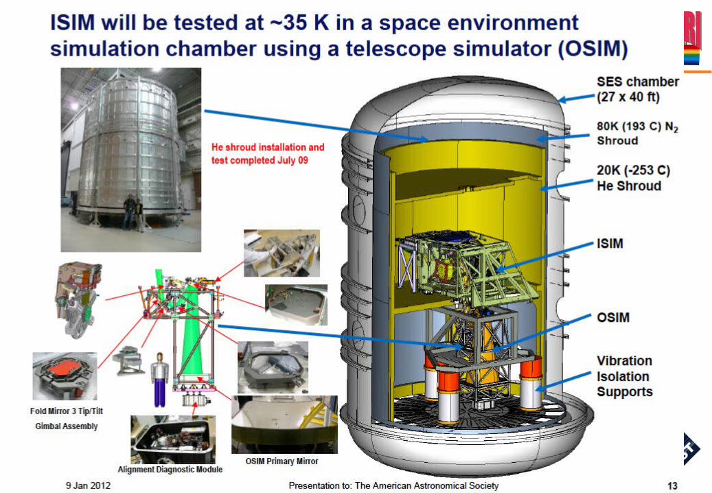
Integrated Science Instruments Module ISIM
7

JWST Thermal
8
Observatory Core Area- ISIM Electronics Compartment (IEC)
- Sunshield Close-Out- Deployed Tower Assembly
- MIRI Cryo-Cooler Refrigerant Deployed Line Assembly (RLDA)
Sunshield MembraneManagement Subsystem
Backplane Support Frame (BSF)
Cryogenic RadiatorsOTE “BIB”
OTE “Frill”
MIRI Radiative Shield

MIRI subsystems
9

10
11

JWST instruments
12

MIRI
13

MIRI overview
14

MIRI Imager MIRIM focal plane layout
15

MIRIM filters
16
Filter name λ(μm) Δλ(μm) Comment
F560W 5.6 1.2 Broad Band
F770W 7.7 2.2
F1000W 10 2 Silicate, Broad Band
F1130W 11.3 0.7 PAH, Broad Band
F1280W 12.8 2.4 Broad Band
F1500W 15 3 Broad Band
F1800W 18 3 Silicate, Broad Band
F2100W 21 5 Broad Band
F2550W 25.5 4 Broad Band
F2550WR 25.5 4 Redundant Filter
FND Neutral Density For Coron. Acquis.
F1065C 10.65 0.53 Phase mask, NH3, silicate
F1140C 11.4 0.57 Phase mask, cont. or PAH
F1550C 15.5 0.78 Phase mask, cont.
F2300C 23 4.6 Focal Plane Mask, Debris Disk
OPAQUE Blackened Blank N/A For Darks

Coronograph
17

Imager filter wheel
18

Low resolution spectrograph
19

MIRIM summary
20

Calibration sources
Injected through hole in pupil plane image
Hot filament, non-imaging flux concentrator.
One for MIRIM, one for MRS
21

Medium Resolution Spectrometer - MRS
22

Spectrometer pre-optics
LT: light trapBF: blocking filter
Dichroics on 2 dichroic wheel assembliesWheel 1: 1a / 1b / 1c
Wheel 2+3: 2a+3a / 2b+3b / 2c+3c

MRS dichroic filtering scheme
System transmissions:
S[1a] = (1 - t[1a]) * t[blocking1]S[1b] = (1 - t[1b]) * t[blocking1]S[1c] = (1 - t[1c]) * t[blocking1]S[2a] = t[1a] * (1 - t[2a]) * t[blocking2]S[2b] = t[1b] * (1 - t[2b]) * t[blocking2]S[2c] = t[1c] * (1 - t[2c]) * t[blocking2]S[3a] = t[1a] * t[2a] * (1 - t[3a])S[3b] = t[1b] * t[2b] * (1 - t[3b])S[3c] = t[1c] * t[2c] * (1 - t[3c])S[4a] = t[1a] * t[2a] * t[3a])S[4b] = t[1b] * t[2b] * t[3b])S[4c] = t[1c] * t[2c] * t[3c])

System transmissions from component dichroic transmission fts measurements

MRS channels
26

MRS Anamorphic pre-optics + IFU
27

Anamorphic pre-optics (APO)
assymetric magnification square input field to rectangular image on slicer
28

IFU
29

Spectrometer main optics
30

Gratings are on the same wheels as dichroics
31

MRS IFU
32

MRS focal plane arrays
33

34
MRS cube reconstruction
D2c calibration file: camera (x,y) to (lambda, s/c

MRS field and spatial resolution
Channel Wavelength Pixel Size Slice Width Slices FOV Resolving Power
µm arcsec arcsec # arcsec21 5.0 - 7.7 0.196 0.176 22 3.00 x 3.87 2400 - 37002 7.7 - 11.9 0.196 0.277 16 3.50 x 4.42 2400 - 36003 11.9- 18.3 0.245 0.387 16 5.20 x 6.19 2400 - 36004 18.3 - 28.3 0.273 0.645 12 6.70 x 7.73 2400 - 3600

36
MRS summary

37
Detectors: Focal Plane Module (FPM)
Raytheon Si:As 1024x1024 BIB detectors
SB305 ROIC

INTEGRATION RAMPS
38
2.7 or 27 secnds(fast/slow mode)
(for full frame)

Subarrays
39
Time between two frames depends on size subarray
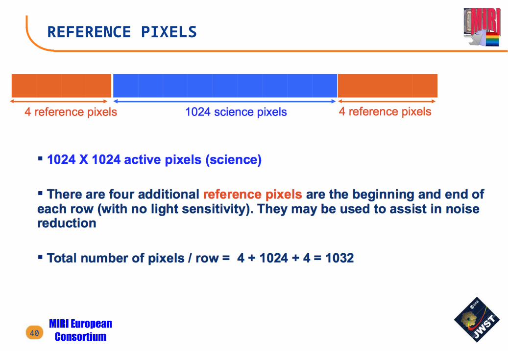
REFERENCE PIXELS
40

REFERENCE OUTPUT
41

LVL1 VERSUS LVL2
42
LVL 1 LVL2

LVL2 STRUCTURE
43

LVL2 EXTENSIONS
44