1 MFGT 142 Polymer Processing Blow Molding Professor Joe Greene CSU, CHICO.
30
1 MFGT 142 Polymer Processing Blow Molding Professor Joe Greene CSU, CHICO
-
Upload
brendan-howard -
Category
Documents
-
view
219 -
download
0
Transcript of 1 MFGT 142 Polymer Processing Blow Molding Professor Joe Greene CSU, CHICO.
1
MFGT 142Polymer Processing
Blow Molding
Professor Joe Greene
CSU, CHICO
2
Blow Molding
• Overview– Blown-Film Extrusion– Extrusion blow molding (continuous and intermittent)– Injection blow molding (hot and cold parisons)– Molds and dies– Plant concepts (layout and capacity)– Product considerations (materials, shapes, designs)– Operation and control of the process
3
Blow Film Extrusion• Blow molding of plastic film is a plastic forming process
that is well suited for the manufacture of film and bags.
• Process– Melting resin in extruder
– Form molten resin into cylinder or tube.
– Blow air inside the resin bubble.
– Pull film into nip rollers through guide rolls.
– Pull film through a series of rollers.
– Wind-up film in take-up rolls

4
Blown Film Equipment• Equipment– Extruder and screen changer
• 2” to 8” diameters
• L/D ratios from 20:1 to 34:1
• Screws are deep cut with melt separation flights.
– Die block with oscillator, tubular die• Die diameters 6” to 36” (max. range from 2” to 100”)
– Air cooled ring: Single and dual-cooling orifice configurations
– Tower structure with collapser and primary nip– Surface treater, secondary nip, and winder(s)
5
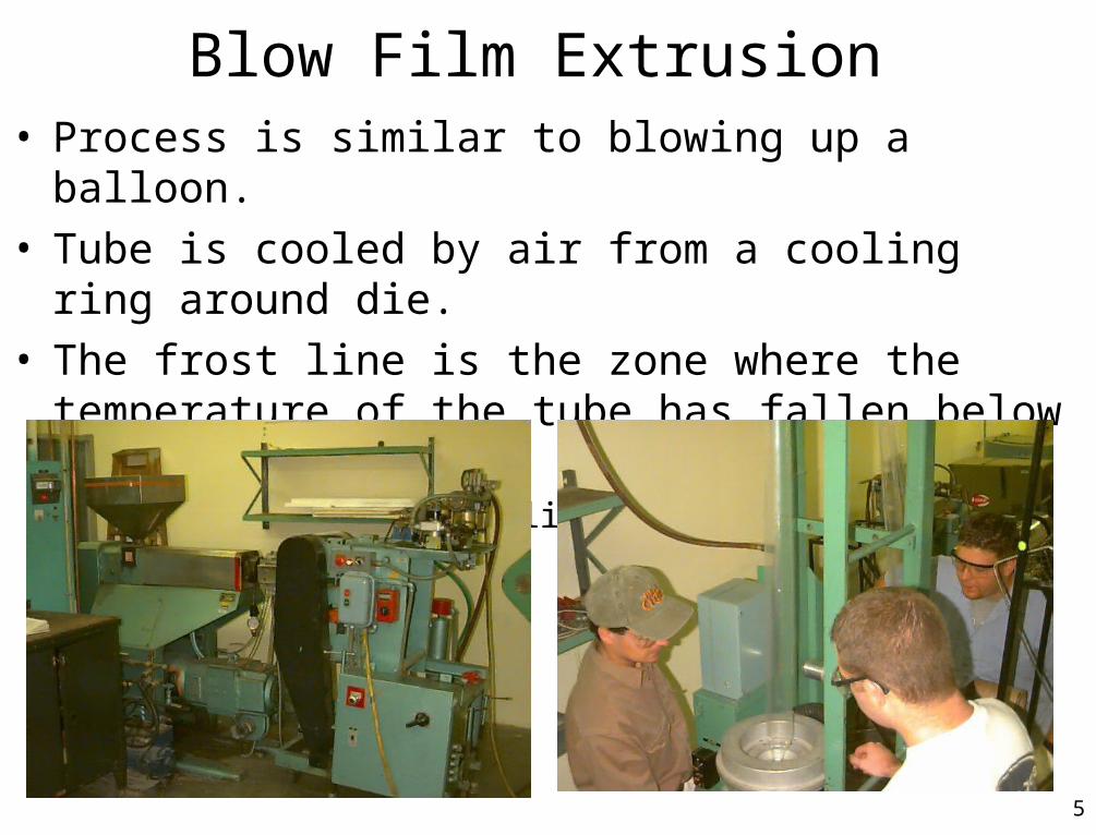
Blow Film Extrusion• Process is similar to blowing up a balloon.
• Tube is cooled by air from a cooling ring around die.
• The frost line is the zone where the temperature of the tube has fallen below the softening point of the plastics. – Example, HDPE frost line actually appears frosty.
6
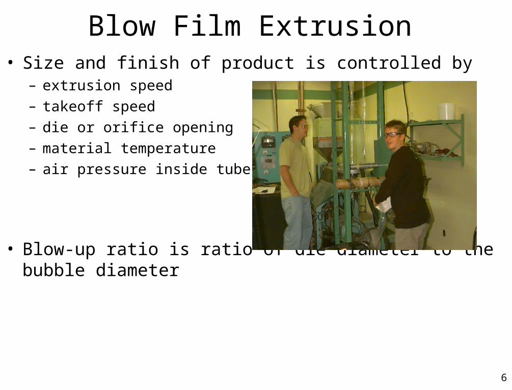
Blow Film Extrusion• Size and finish of product is controlled by
– extrusion speed
– takeoff speed
– die or orifice opening
– material temperature
– air pressure inside tube.
• Blow-up ratio is ratio of die diameter to the bubble diameter
7
Blow Film Extrusion• Film producers may slit the tubing on one edge during windup.
– If tube is blown to a diameter of 2m the flat film will have a width of over 6 m.
– Slot dies are not practical.Tubular films are desired as low-cost packaging for some foods and garments.
– Only one heat seal is needed in the production of bags from blown tubing.
• Blown films are semi-oriented– Less orientation than highly oriented sheets from slot dies.
– Stretching from the tubing expanding under pressure results in less orientation. This stretching provides balanced orientation.
– Products are biaxially oriented. Machine and cross directions.
– Improved physical properties result.
8
Troubleshooting Blow Film• Table 11-3 (ITEC-041 Book) Pg. 179
9
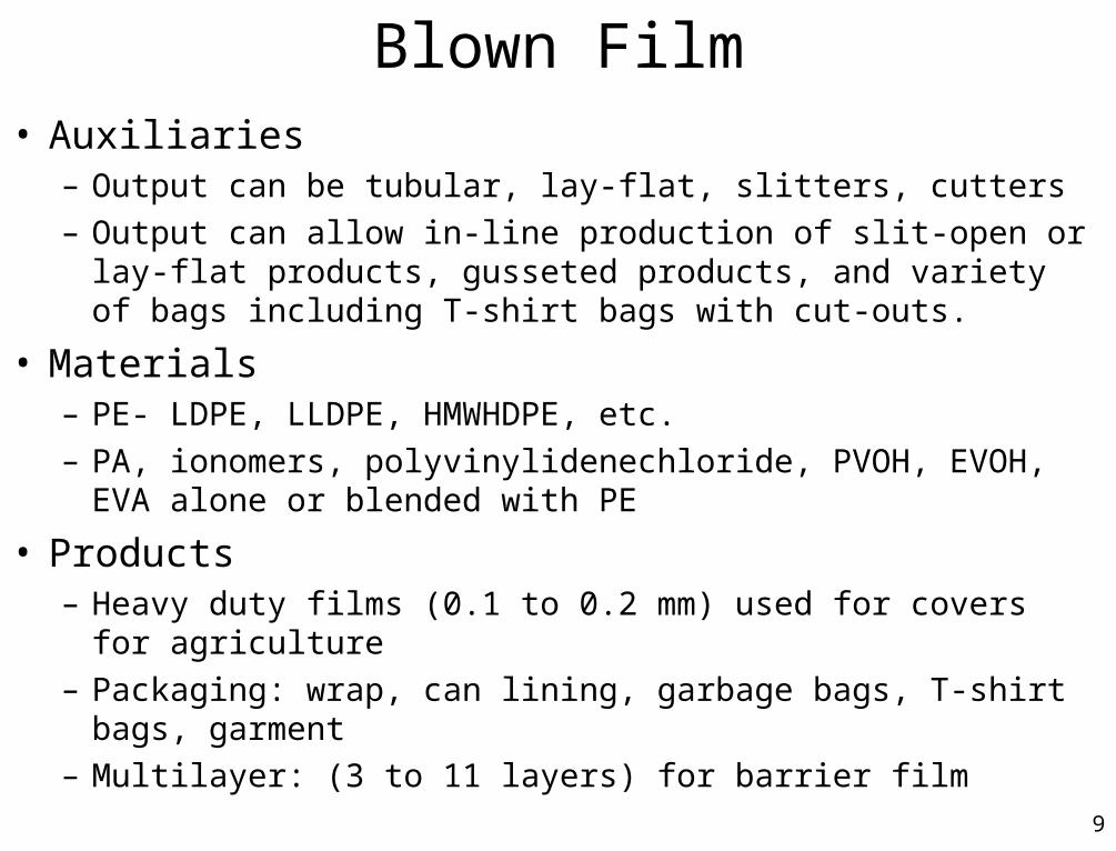
Blown Film• Auxiliaries
– Output can be tubular, lay-flat, slitters, cutters– Output can allow in-line production of slit-open or lay-flat
products, gusseted products, and variety of bags including T-shirt bags with cut-outs.
• Materials– PE- LDPE, LLDPE, HMWHDPE, etc.– PA, ionomers, polyvinylidenechloride, PVOH, EVOH, EVA alone
or blended with PE
• Products– Heavy duty films (0.1 to 0.2 mm) used for covers for agriculture– Packaging: wrap, can lining, garbage bags, T-shirt bags, garment– Multilayer: (3 to 11 layers) for barrier film

10
Blown Film Operation and Costs• Operation
– Operating Pressure of 3,000 to 6,000 psi with max of 10,000 psi– Production rates with internal cooling range from 6 to 20 lbs per inch of lay-
flat width.– Typical Production rates of 700 lbs per hour of product & 300 ft/min– Typical production plant has 5 to 10 lines in operation.– Nip treater widths range from 24” to 144” (max. of 244”)– Tension controlled nip treaters with typical tension levels of 0.125 and 1.0
lb/linear inch per mil of film thickness (1 mil =0.001”)
• Costs– Every year 90 new blown film lines are built (60% to replace existing)– Annual output of over 4 Billion lbs of resin over 2500 existing lines.
– Production Costs (typical) are $200/hour per machine– Single-layer blown film line is $330K to $660K.– Coextrusion line is $4 million

11
Blown Film Costs Spreadsheet• Operation
------------------------------------------------- --------------------- --------------------- ------------ --------------------- ------------------------------------------------- --------------------- --------------------- EXTRUSION TECHNICAL COST MODEL from IBIS Cost Model EXTRUSION TECHNICAL COST MODEL from IBIS Cost Model Roplast uses rates 800 lbs/hr or 300 ft/min of LDPE, $200/hour billing machine------------------------------------------------- --------------------- --------------------- ------------ --------------------- ------------------------------------------------- --------------------- ---------------------
Updated: 3/2/99 per hour per yearPRODUCT SPECIFICATIONS VARIABLE COST ELEMENTS --------------------- ---------------------
Part Name Sheet NAME Material Cost $12.68 $634,128Width 100 cm WDTH Direct Labor Cost $0.41 $20,658
Maximum Wall Thickness 1 mm THKM Utility Cost $0.01 $503Average Wall Thickness 1 mm THKA
External Surface Area 100 sq cm SAREA FIXED COST ELEMENTS --------------------- ---------------------Projected Area 100 sq cm PAREA Equipment Cost $37.82 $1,890,863
Tooling Cost $15.60 $780,000Number of Cavities 1 CAV Building Cost $0.40 $20,116
Number of Actions in Tool 1 ACT Maintenance Cost $16.31 $815,461Surface Finish [3=best] 1 [1,2 or 3] FIN Overhead Labor Cost $6.62 $331,060
Cost of Capital $30.40 $1,520,144Annual Production Volume 50 (000/yr) NUM =========== ===========Length of Production Run 1 yrs PLIFE TOTAL OPERATION COST $120.26 $6,012,933
MATERIAL SPECIFICATIONS ------------------------------------------------- --------------------- ---------------------Material Type HDPE MATMaterial Price $0.88 $/kg PRICE INTERMEDIATE CALCULATIONS
Scrap Credit Value $0.00 $/kg SCPRI Part Name SheetDensity 0.94 g/cm^3 DENS Material Designation HDPE
Thermal Conductivity 0.24 W/mK TCOND Product Weight 100 gHeat Capacity 1675 J/kgK HTCAP Raw Material Price $0.88 /kg
Melt Temp 220 C MTEMP Material Scrap Price $0.00 /kgTool Temp 45 C TTEMP Material Density 0.94 g/cm^3Eject Temp 80 C ETEMP
Adjusted Material Scrap 0.005PROCESS RELATED FACTORS Cumulative Rejection Rate 0.001
Dedicated Investment 0 [1=Y 0=N] DED Effective Production Volume 50050 /yrOperation Rejection Rate 0.1% REJ Tool Complexity Factor 19542
Material Scrap Rate 0.5% SCR Energy Adjustment Factor 2.6Average Equipment Downtime 20.0% DOWN Clamping Force 424 kN
Direct Laborers Per Station 0.5 NLAB Cooling Time 0.9 sec
OPTIONAL INPUTS CALCULATED Cycle Time 9144.0 secProduction Rate 9144 cm/minute OCYCLE 9144.0
Equipment Cost per Station $330 (000) OEQUIP $330,000 Runtime for One Station 2546.6%Tool Cost per Set $30 (000) OTOOL $30,000 Number of Parallel Stations 25.47
Productive Tool Life 1 yrsEXOGENOUS COST FACTORS EXOG Tool Sets/Station 1
Direct Wages 12 /hr WAGEIndirect Salary $50,000 /yr SALARY Equipment Investment/Station $330,000 /station
Indirect:Direct Labor Ratio 0.4 ILAB Tooling Investment/Set $30,000 /tool setBenefits on Wage and Salary 30.0% BENI
Working Days per Year 260 DAYS Power Consumption/Station 0.1 kWWorking Hours per Day 24 HRS Building Space/Station 26.3 sq mCapital Recovery Rate 15.0% CRR
Equipment Recovery Life 8 yrs ELIFE Equipment Annuity $3,257,501 /yrBuilding Recovery Life 20 yrs BLIFE Tooling Annuity $844,818 /yr
Working Capital Period 3 months WCP Building Annuity $63,572 /yrPrice of Electricity $0.051 /kWh ELEC Working Annuity $1,847,042 /yr
Price of Natural Gas $6.50 /MBTU GASPrice of Building Space $600 /sq m PBLD ############################# ############ ############
Auxiliary Equipment Cost 20.0% AUXEquipment Installation Cost 50.0% INST
Investment Maintenance Cost 5.0% MNT
12
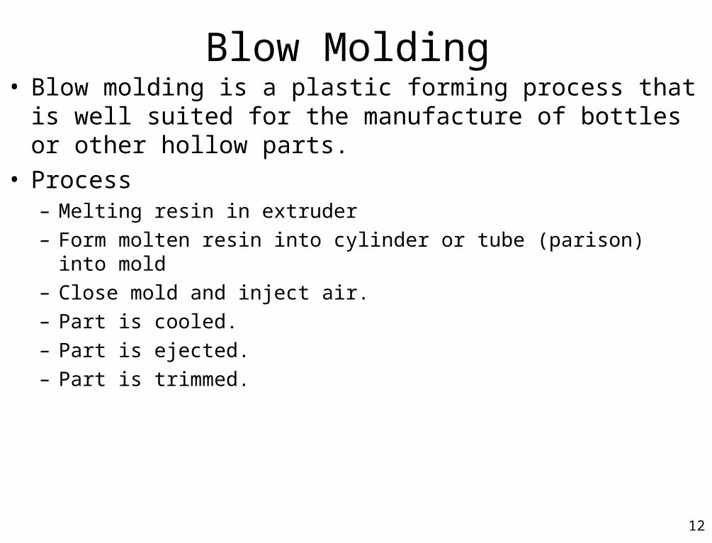
Blow Molding• Blow molding is a plastic forming process that is well suited
for the manufacture of bottles or other hollow parts.
• Process– Melting resin in extruder
– Form molten resin into cylinder or tube (parison) into mold
– Close mold and inject air.
– Part is cooled.
– Part is ejected.
– Part is trimmed.
13
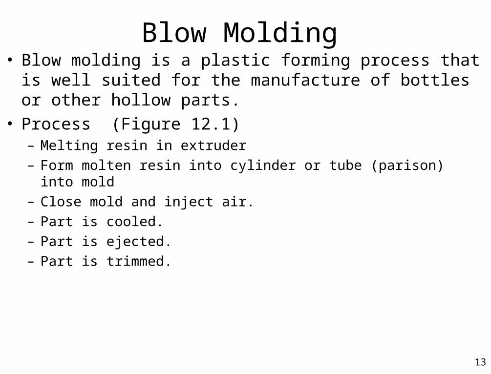
Blow Molding• Blow molding is a plastic forming process that is well suited
for the manufacture of bottles or other hollow parts.
• Process (Figure 12.1)– Melting resin in extruder
– Form molten resin into cylinder or tube (parison) into mold
– Close mold and inject air.
– Part is cooled.
– Part is ejected.
– Part is trimmed.
14
Blow Molding• Principle-
– Inflate a soft end thermoplastic hollow preform (or parison) against a cooled surface of a closed mold (extrusion blow molding).
– OR inject a thermoplastic material into an injection mold featuring a neck ring and core pin. Air is injected to blow the material against a cooled surface (injection blow molding).
15
Blow Molding• Materials
– Good stretchability and a high MW are preferred– HMWPE is the most widely used for high volume packaging– PP used in processes that promote orientation– PVC is used for bottles in Europe (homopolymer can be crystal clear)
– PET is primarily used for injection blow molding. Preforms injected into cold mold to an amorphous state and then reheated to 100C for blowing
– Nitrile, SAN, PVDC, PPO, PC, and PA
• Products – Packaging, bottles for drinks, containers for cosmetics and toiletries, automotive
containers and bumpers.– Coextrusion products for chemical resistance and structural
16
Extrusion Blow Molding
• Extrusion Blow Molding the parison is formed from an extrusion die that is similar to one from blown film.
• Blown film is continuous. The film is made continuously.• Extrusion blow molding is discrete. Each part is molded individually.• Cycle time reduction
– Two mold shuttle system (Figure 12.2)
– Parison transfer system (Figure 12.3)
– Rotating mold or carousel system (Figure 12.4)
– Accumulator system for intermittent extrusion blow molding (Fig. 12.5) Very large parts (up to 120 gal) that are several times the injection volume.
17
Injection Blow Molding• Injection blow molding forms a parison by injecting a molten resin into a
mold cavity and around a core pin.
• The parison is formed by injection called preform and then blown with air to form final shape. (Figure 12.6)
• Traditional injection molding machine is used to create preform.– Mold is closed with core pin in place.
– Resin injected to form a cylindrical part around the core pin.
– Threads, if any, are also formed at this stage.
– Mold is opened, core pin removed, and parison ejected.
– Parison is transferred to a blowing station either still hot or cooled.
– Second mold is closed and air is injected to form part.
– Mold opens and part is ejected.
18
Injection Blow Molding• The injecting and blowing cycles of injection blow molding need not be
done at the same time or even at the same location.
• Parisons can be made by injection and then either stored until the finished blow molded parts are needed or shipped to a satellite location where they can be blown.
• Parison must be reheated if not blown right away.– Example, Soda pop bottles
• Parisons are made in central location on a large, multi-cavity injection molding machine which give economies of scale and close engineering control over injection mold step (critical step).
• Parisons are moved to blow molding site, reheated, and blown into bottles.• Advantages
– The blow molder doesn’t need expensive injection machine and injection molds, but just and oven and a blowing station.
19
Injection Blow Molding• Injection blow molding allows formation of a parison that can have a non-constant
cross-section resulting in better wall thickness uniformity than from extrusion blow molding.
• Stretch blow molding (Figure 12.7)– Mechanical assistance stretches the part in the longitudinal direction at the same time
blowing the part causing a stretch in the part along the hoop or radial direction.– Results in biaxial orientation and increased properties.– Process results from a telescoping mandrel or core pin that extends to push on the bottom of
the preform at the same time that the air is being injected to push against the walls to stretch the material radially.
– Advantage is improvement in mechanical properties.• Higher burst strength and higher impact strength.• PET soda pop bottles use this technique to cause some crystallization and improved properties to pass 6
foot drop test.
20
Comparison Extrusion and Injection Blow Molding
• Extrusion blow molding is characterized by:– Best suited for bottles over 1/2 pound (200 g) and shorter runs.– Machine costs re comparable to injection blow molding.– Tooling costs are 50% to 75% less than injection blow molding.– Generates 20% to 30% scrap due to sprue and head trimming.– Requires additional equipment to grind scrap and reuse.– Total cycle time is shorter due to less parison transfer time.– Wider choice of resins possible due to resins with higher viscosities can be
used.– Final part design flexibility can be greater with the use of asymmetrical
openings.
21
Comparison Extrusion and Injection Blow Molding
• Injection blow molding is characterized by:– Scrap free.– Better suited for long runs and smaller bottles.– Higher accuracy in the final part.– Uniform wall thickness.– No seam lines or pinch marks– Transparencies are best because crystallization can be better
controlled and the blowing can be more stress free.– Improved mechanical properties from improved parison design and
from stretch blowing.
22
Blow Molding Molds• Molds and Dies
– Made from tool steel and is similar to extruded pipe and blown film dies.
• Programmed Parison Formation (Figure 12.8)– Improves part uniformity of extrusion blow molded parts.
– Method employs an extrusion die that has a mandrel with a conical shaped end.
– The slope of the sides of the cone on the mandrel is not quite as steep as the slope of the sides of the opening.
– When the mandrel and outer die move relative to each other, the gap between them will open or close, depending on the direction of movement.
– Feature is used to make prison that is thicker at the bottom than at the top, thus compensating for the natural thickness variation in blow molded due stretching.
– Variation in thickness is accomplished by timing the movement of die/mandrel with the extrusion of the parison.
23
Blow Molding Molds• General Mold Considerations
– Does not require high pressure like injection molding.– Aluminum (cast or machined) is the most common material.– Disadvantage to Al is the excessive wear.– Steel inserts can be used for wear areas, e.g., pinch-off.– Cast steel can be used for long production runs.– Epoxy molds with Al filler can be used for prototype.– Molds are two halves with cooling lines.– Proper venting is important to prevent air traps.– Surface of the mold is not polished or chromed.– Engraving of logos is common.– Blowing point is through a hole in the top or bottom of mold.– Ejection can be through gravity or mechanical assist.
24
Blow Molding Molds• Sliding/Compression Blow Molds
– Molding a recessed ring or lip onto blow molded part by applying compression to certain areas of part, e.g., flower pot, undercuts, etc.
– Process (Two flower pots are made)• Mold closes around parison which is blown in normal method.
• The parison flows around a recess in the side of the mold (top of flower pot).
• Before the parison is cool, the upper and lower sections of the mold slide toward the center portion, which is fixed. The sliding motion compresses the material that is in the gaps between the sliding parts of the mold and the fixed parts. The reinforcement ring is formed.
25
Plant Concepts
• Blow molding equipment are self contained and do not need extensive cooling or part removal as in extrusion.
• Removal and handling of scrap.– Scrap removal station automates pinch-off removal.– Scrap is chopped and blended with virgin material.
• Common practice is 2% regrind. Max is 50%. Properties drop after 20%.
• On-line filling and labeling is done with automation.

26
Product Considerations• Materials
– HDPE (stiff bottles, toys, cases), LDPE (flexible bottles), PP (temperature resistant bottles), PVC (clear bottles, oil resistant), PET (soda pop), PC (housings), nylon (fluid containers), and FEP.
– Polyolefins (HDPE, LDPE, PP) are easiest to process but are sensitive to oils and can have stress cracking problems.
– PVC is very temperature sensitive and rarely used because of thermal degradation and safety concern for HCl.
– Post consumer regrind can be used with virgin material.
• Shapes– Hollow parts that are usually cubical or cylindrical.– Molded parts can be cut in two to yield two parts.– Wall thickness is limited to 1 cm (0.5 in) or less.– Wall thickness variation is a problem with thicker at bottom due to parison sag.
27
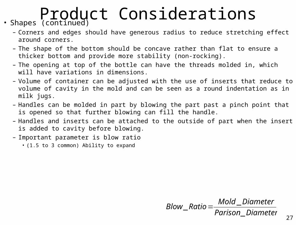
Product Considerations• Shapes (continued)
– Corners and edges should have generous radius to reduce stretching effect around corners.– The shape of the bottom should be concave rather than flat to ensure a thicker bottom and
provide more stability (non-rocking).– The opening at top of the bottle can have the threads molded in, which will have variations in
dimensions.– Volume of container can be adjusted with the use of inserts that reduce to volume of cavity in
the mold and can be seen as a round indentation as in milk jugs.– Handles can be molded in part by blowing the part past a pinch point that is opened so that
further blowing can fill the handle.– Handles and inserts can be attached to the outside of part when the insert is added to cavity
before blowing. – Important parameter is blow ratio
• (1.5 to 3 common) Ability to expand
DiameterParison
DiameterMoldRatioBlow
_
__
28
Operation and Control
• Important process control parameters– stretch (sag) of parison,– temperature of the parison and temperature of work space,– melt flow characteristics of resin– speed of parison formation– crystalline nature of the polymer,– cooling capacity of the mold.

29
Trouble-shooting Guide for Blow MoldingTable 12.1
30
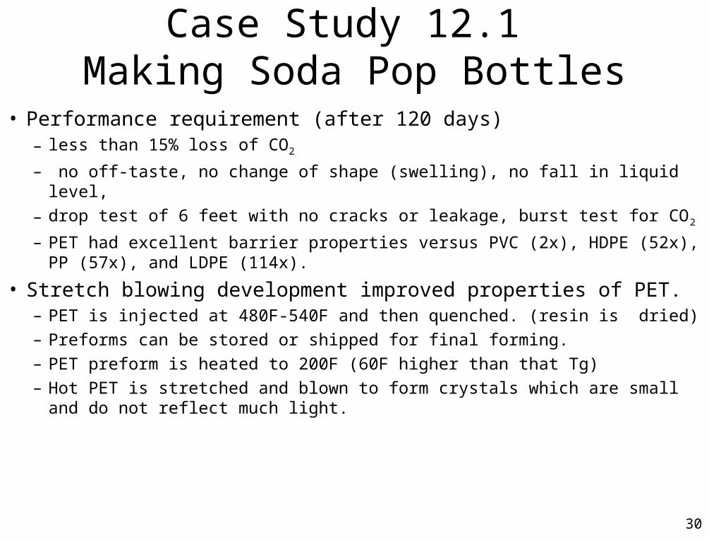
Case Study 12.1 Making Soda Pop Bottles
• Performance requirement (after 120 days)– less than 15% loss of CO2
– no off-taste, no change of shape (swelling), no fall in liquid level,
– drop test of 6 feet with no cracks or leakage, burst test for CO2
– PET had excellent barrier properties versus PVC (2x), HDPE (52x), PP (57x), and LDPE (114x).
• Stretch blowing development improved properties of PET.– PET is injected at 480F-540F and then quenched. (resin is dried)– Preforms can be stored or shipped for final forming.– PET preform is heated to 200F (60F higher than that Tg)– Hot PET is stretched and blown to form crystals which are small and do not reflect
much light.