1 Luis San Andrés Mast-Childs Professor, Fellow ASME Texas A&M University On the Effect of Thermal...
35
1 Luis San Andrés Luis San Andrés Mast-Childs Professor, Fellow ASME Texas A&M University On the Effect of Thermal Energy Transport to the Performance of (Semi) Floating Ring Bearing Systems for Automotive Turbochargers ASME Turbo Expo 2012 June 11-15, 2012, Copenhagen, Denmark Accepted for journal publication GT2012- 68355
-
Upload
nestor-meaker -
Category
Documents
-
view
213 -
download
0
Transcript of 1 Luis San Andrés Mast-Childs Professor, Fellow ASME Texas A&M University On the Effect of Thermal...

1
Luis San AndrésLuis San AndrésMast-Childs Professor, Fellow ASME Texas A&M University
On the Effect of Thermal Energy Transport to the Performance of (Semi) Floating Ring Bearing Systems for Automotive Turbochargers
ASME Turbo Expo 2012 June 11-15, 2012, Copenhagen, Denmark
Accepted for journal publicationGT2012-68355

2
AuthorsAuthors
Supported by Honeywell Turbocharger Technologies (HTT)
Thermal Energy Transport to the Performance of (Semi) Floating Ring Bearing Systems for Automotive Turbochargers
Vince BarbarieAvijit Bhattacharya
Kostandin Gjika
Honeywell Turbo TechnologiesTorrance, CA 90504
Honeywell Turbo Technologies,Thaon-les-Vosges, France
Luis San AndrésTurbomachinery Laboratory Texas A&M University
GT2012-68355

3
Fully Floating Bearing Semi Floating Bearing Ball Bearing
Types of bearing supports
Increased IC engine performance & efficiency demands of robust turbocharging solutions
The driver:
Oil lubricated bearings are economic with longer life span; but prone to harmful subsynchronous whirl & depend on engine oil condition.
Low shaft motion, expensive, limited
lifespan

4
Major challenges
extreme operating conditions:• - Low Oil Viscosity, e.g. 0W30 or 0W20
• - High Oil Temperature (up to 150°C)
• - Low HTHS (2.9); Low Oil Pressure (1 bar),
• - Increased Max. Turbocharger Speed 5 kHZ
• - Variable Geometry Turbo Technology & Assisted e-power start up
• - High Engine Vibration Level• - More Stringent Noise Requirements
Need predictive too to reduce costly engine test stand qualification
Thermal management & reduce thermal loading

5
• TC linear and nonlinear rotordynamic codes – GUI based – including engine induced excitations
• Realistic bearing models: thermohydrodynamic
• Novel methods to estimate imbalance distribution and shaft temperatures
• NL analysis for frequency jumps (internal & combined resonances) and noise reduction
• Measured ring speeds with fiber optic sensors
Literature Review: TAMU work
Predictive tool for shaft motion benchmarked by test data
2004 IMEchE J. Eng. Tribology
2005 ASME J. Vibrations and Acoustics ASME DETC 2003/VIB-48418 ASME DETC 2003/VIB-48419
2007 ASME J. Eng. Gas Turbines Power ASME GT 2006-90873
2007 ASME J. Eng. Gas Turbines Power ASME GT 2005-68177
2007 ASME J. Tribology IJTC 2006-12001
2007 ASME DETC2007-34136
2010 ASME J. Eng. Gas Turbines Power ASME GT2009-59108
2010 IFToMM Korea

6
VIRTUAL TOOL for TC NL shaft motions
Tool demonstrated 70% cycle time reduction in the development of new CV TCs. Since 2006, code aids to develop PV TCs with savings up to $1XX k/year in qualification test time
ASME DETC2007-34136
Predicted Steady-State Waterfall / Y DisplacementRBS with ODminIDmax / Oil Texaco-Havoline Energy 5W30, 150°C, 4bar
0
0.01
0.02
0.03
0.04
0.05
0.06
0.07
0 500 1000 1500 2000 2500 3000 3500 4000 4500 5000 5500 6000
Frequency (Hz)
Mo
tio
n A
mp
litu
de
Subsynchronous ComponentsSynchronous Component
Predicted Steady-State Waterfall / Y DisplacementRBS with ODminIDmax / Oil Texaco-Havoline Energy 5W30, 150°C, 4bar
0
0.01
0.02
0.03
0.04
0.05
0.06
0.07
0 500 1000 1500 2000 2500 3000 3500 4000 4500 5000 5500 6000
Frequency (Hz)
Mo
tio
n A
mp
litu
de
Subsynchronous ComponentsSynchronous Component
Measured Steady-State Waterfall / Y DisplacementRBS with ODminIDmax / Oil Texaco-Havoile Energy 5W30, 150°C, 4bar
0
0.01
0.02
0.03
0.04
0.05
0.06
0.07
0 500 1000 1500 2000 2500 3000 3500 4000 4500 5000 5500 6000
Frequency (Hz)
No
rma
lize
d N
on
lin
ea
r R
es
po
ns
e
Subsynchronous ComponentsSynchronous Component
Predicted shaft motion Measured shaft motion
TC testing is expensive and time consuming
Predictive tool saves time and resources

7
Thermal energy analysis in TCs complicated b/c of a) Hot gas -work and heat flow from turbine b)Cold gas +work and heat flow from the
compressorc) internal heat flow across shaft from T to C and
radially thru bearingsd)Mechanical drag power in bearingse) Heat flow to/from casing to ambient (convective and
radiant)
Conjugate heat transfer in TCs
Engine lubricated bearings: (a) low friction-load support (b) oil carries away heat (cooling)

8
turbinecompressor
Heat flows & energy transfer in a TCHot air (energy) in
-Hot air (energy) out
Heat conducted (casing)
Heat conducted (shaft)
Cold air (energy) in
Compressed hot air (energy) out
Heat conducted (casing)
Bearing drag power generation
Oil in
Oil out
Baines, N., Wygnant, K., Dris, A., 2010, J Eng Gas Turb. Power, 042301
Heat conducted (casing)
work

9
a) Lumped parameter models with empirical formulas for heat transfer coefficients and simplified formulas for drag power, flow & heat flow in the lubricated bearings
b)Current 3D modeling stresses on solids with over-simplified coupling to the lubricant flows
Thermal energy analyses in TCs use
avoid oil coking, optimize flow rates, ensure proper clearances,
eliminate seizure.
Engineered thermal management to avoid severe thermal loading with improved reliability of bearing system:
GOAL

10
SFRB system in engine-oil lubricated TC
turbine
compressor
Semi-floating
ring bearing
Compressor side bearing oil supply holesto inner and outer filmsOil supply
holes to inner film
Turbine side bearing Outer film with ½ moon groove
Oil supply at
Psup, Tsup
Anti-rotation pin
shaft
casing
Oil discharges at
ambient pressure Pa
Lubricant flow paths into bearings on turbine and compressor sides

11
Definitions:X,Y: fixed (inertial) coordinate systemg : direction of gravity
Circumferential coordinate
X
gRing rotation
R
0º
Oil supply hole
DRo
DB
Y
Z
Lo
outer film
shaft
Ring
Casing
Y
½ moon groove
LG
Shaft rotation
inner film
Li
ShaftDRi
DJ
Geometry & coordinate system for typical SFRB

12
Kinematics of journal and ringNomenclature: : journal rotational speed
R: ring rotational speed
Circumferential (angular) coordinate
co : radial clearance outer film
ci : radial clearance inner film
ho: outer film thickness
hi : inner film thickness
eRX, eRY: Ring center eccentricity components
eX, eY: Shaft (journal) center eccentricity components
eJX, eJY : Eccentricity of journal relative to ring
X
Y
OR
eReJ
e
R
ring
journal
ring rotation
Journal rotation
cos sinX Yo o R Rh c e e cos sin
X Yi i J Jh c e e
Inner film thickness
=e eR eJ+
Journal rotation
X
Y
OR
eRX
eRY
eX
eY
eJX
eJY
eReR
eJeJee
R
OJ
ring
journal
ring rotation
=e eR eJ+=e eR eJ+=e eR eJ+ee eReR eJeJ+Outer film thickness

13
Shaft, TS
Casing, TC
Ring, TR(r)
Inner film, Ti(,z)
Outer film, To(,z)
R TRi
TRo
TRM
Ro
Ri
RM
Pi,Ti
Po,To
TS
TC
Oil inlet,Psup, Tsup
Feedhole
Inlet½ moongroove
zRs
Rc
PA, ambientpressure
PA
z
Axial view of inner and outer films: nomenclature

14
Hydrodynamic pressure generation
3 3
2
( ) ( )
1
12 12
2
i i i i
J i T i T
i iR
h P h P
R z z
h h
t
Nomenclature
P : film pressure
h : film thickness
: viscosity, fn (T)
Major assumptions:Laminar flow without fluid inertia effectsAverage viscosity across film thickness
V ST TS e
3 3
2
( ) ( )
1
12 12
2
o o o o
B o T o T
o oR
h P h P
R z z
h h
t
Innerfilm
Outerfilm
journal rotational speed
R ring rotational speed
circumferential coordinateZ axial coordinate
RJ: Shaft (journal) radius
RB: Bearing casing inner diameter
Reynolds equations for inner & outer films
TRM
Ring
Pi,Ti
Po,To
TS
Casing TC
shaft

15
shaft
Ring
TS
casing
Outer film
Inner filmTRi
TRo
TC
Ti
To
Heat flow from shaft Mechanical
drag power
Heat flow into ring
Mechanical drag power
Heat flow into casing
Flow outer
Flow inner
Heat flow
carried
by oil
Heat flows & power in a FRB
16
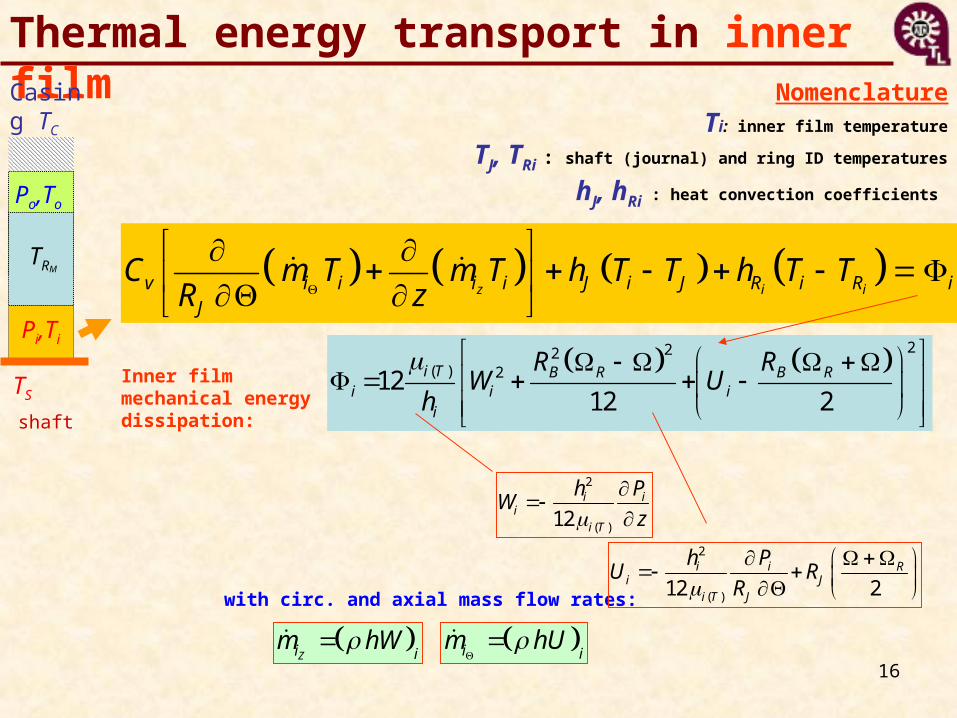
NomenclatureTi: inner film temperature
TJ, TRi : shaft (journal) and ring ID temperatures
hJ, hRi : heat convection coefficients
z i iv i i i i J i J R i R i
J
C m T m T h T T h T TR z
i im hU
Zi im hW
222( ) 212
12 2i T B R B R
i i ii
R RW U
h
with circ. and axial mass flow rates:
Inner film mechanical energy dissipation:
2
( )12i i
ii T
h PW
z
2
( )12 2i i R
i Ji T J
h PU R
R
Thermal energy transport in inner film
TRM
Pi,Ti
Po,To
TS
Casing TC
shaft

17
TRM
Pi,Ti
Po,To
TS
Casing TC
shaft
Thermal energy transport in outer filmNomenclature
To: outer film temperature
TB, TRo : bearing casing and ring OD temperatures
hB, hRo : heat convection coefficients
z o ov o o o o B o B R o R o
B
C m T m T h T T h T TR z
o om hU
Zo om hW
2 2( ) 212
12 2o T B R B R
o o oo
R RW U
h
with circ. and axial mass flow rates:
Outer film mechanical energy dissipation:
2
( )12o o
oo T
h PW
z
2
( )12 2o o B R
oo T B
h P RU
R

18
0R
R R R R R RA
q k T q dA
Heat conduction in semi-floating ringNomenclature
TR: ring temperature
TJ, TRi : shaft (journal) and ring ID temperatures
hJ, hRi : heat convection coefficients
kR: ring material conductivity
qR : heat flow
Major assumptions:Steady state, no heat flow in
axial direction,No effect of ring rotation
10R R
T Tr
r r r r r
r

19
Heat conduction in semi-floating ring
Major simplificationRadial heat conduction only
10R R
T Tr
r r r r r
r
1
0RT
rr r r
( )
ln2r M
M
RR R
R R
Q rT T
L R
TRM
Ring
Pi,Ti
Po,To
TS
Casing TC
shaft
Nomenclature
TR: ring temperature
QR: radial heat flow
kR: ring material conductivity
Ring
R
TR
TiInner film
i ii R R i R RiQ h T T R z
oR o R Ro o RoQ h T T R z
ToOuter film
r

20
1 Reynolds/Colburn Analogy), Nu=3 Pr0.33
2 Kays and Crawford - constant wall temperature, Nu =7.54
3 Kays and Crawford - constant wall heat flux, Nu =8.22
4 Haussen - thermally developing constant wall temperature, Nu >3.657
5 Shah - thermally developing constant wall heat flux, Nu > 4.364
6 Stephan - Simultaneous developing, constant wall temp, Nu >3.66
7 Stephan - Simultaneous developing constant wall heat flux, Nu > 4.364
Heat flow: Q = h A (TS – Ti)A: wetted area for heat transfer
h: heat convection coefficient, a function of Nusselt #, oil conductivity and hydraulic diameter (=clearance).
Nusselt # =depends on flow conditions (Prandtl # and Reynolds #)
Ti
Ts
; Re,Proil
H
kh Nu Nu f
D
Pr ; Rep
oil
C Rc
k
Heat convection Models

21
Numerical method of solution
a) Finite element method for Reynolds Eqns.
WN
WP
UEUW
PPPE
PS
WS
PW
x=R
z
PN
UP
U,P=T,W-cvs
TN
TW TE
TS
TP
e
x=R
z Nodal pressures
q Flow rate
Flowdomain
b) Control volume method for energy transport Eqns.
Includes balance of drag torques, material properties f(T), bearing clearance changes due to temperature rise, etc.

2222
Example Semi FRB for PV turbine bearing
Oil: SAE 5W-30120C
213C
Shaft (journal)
RING
CASING
Oil inlet
Bearing dimensionsInner Film Outer film
Diameter 7.9 14.1 mmlength 4.6 6.2 mm
Cold clearance 7.5 35 m
Oil supply temperature 120 C Turbine temperature 700 CSupply pressure 4 bar Defect temperature ratio 0.16 CInlet presure loss 0.9
Journal Temperature 213 CCasing Temperature 120 C
Speed range 30-240 krpm
Average load 44.1 NOil supply temperature 120 C Turbine temperature 700 CSupply pressure 4 bar Defect temperature ratio 0.16 CInlet presure loss 0.9
Journal Temperature 213 CCasing Temperature 120 C
Speed range 30-240 krpm
Average load 44.1 N

2323
Meshes for inner and outer flow domains
X
=132 ºY
Z
Casing½ moon groove
Feed hole x 4
groove
journal
ring
132o
1 3 5 7 9 11 13 15 17 19 21 23 25 27 29 31 33 35 37 39 41 43 45
S1
S3
S5
S7
S9
S11
0.05.010.0
15.0
20.0
circ coordinate (node #)
axial coordinate
15-20
10-15
5-10
0-5
Inner Film
Filed name: Clearances_outer
1 4 7
10
13
16
19
22
25
28
31
34
37
40
43
46
49
52
S1
S4
S7
S10
0.01.02.03.04.05.0
clearance
circ coordinate (node #)
axial coordinate
4-5
3-4
2-3
1-2
0-1
Inner Film
Filed name: Clearances_inner
½ moon grooveCirc. groove
Oil supply hole(4x) Axial groove
(4 x)
Mesh: outer film
Mesh: inner film
NEX=45, NEY=12
NEX=52, NEY=12
z
z
Engineered design to improve flow delivery and reduce temperature rise

24
1 6
11 16
21
26
31
36
41
46
51S
1 S7 S13
0
50
100
150
200
250
circ coordinate (node #)axial
coordinate
200.0-250.0
150.0-200.0
100.0-150.0
50.0-100.0
0.0-50.0Inner Film
Temperature
(b) Temperature field (C)
z
1
6
11
16
21
26
31
36
41
46
51
S1
S6
S11
-1.0
0.0
1.0
2.0
3.0
4.0
5.0
6.0
circ coordinate (node #)
axial coordinate
5.0-6.0
4.0-5.0
3.0-4.0
2.0-3.0
1.0-2.0
0.0-1.0
-1.0-0.0
Inner Film
Pressure
(a) Pressure field (bar)
z
Tsup=120C
TS=213C
240 krpm
Feed hole & axial groove
Predictions for inner film at
1 4 7
10
13
16
19
22
25
28
31
34
37
40
43
46
49
52 S1
S4
S7
S10
0.01.02.03.04.05.0
clearance
circ coordinate (node #)
axial coordinate
4-5
3-4
2-3
1-2
0-1
Inner Film
Filed name: Clearances_inner
inner film
z
Oil heats quickly along axial plane

25
0.00.10.20.30.40.50.60.70.80.91.01.1
0 40 80 120 160 200 240
rotor speed (krpm)
Max
. fi
lm t
emp
erat
ure
s [-
]
Oil inlet temperature
Lubricant flash temperature ~ 1.18
Temperatures: maximum in films sup
supS
T TT
T T
Shaft Temp
inner film
outer film
exit mixed films
Inner film temperature
shaft T (< flash T).Outer film
relatively cold.

26
0.00.10.20.30.40.50.60.70.80.91.01.1
0 40 80 120 160 200 240
rotor speed (krpm)
Ave
rag
e fi
lm t
emp
erat
ure
s [-
]
Oil inlet temperature
Lubricant Flash point ~ 1.2
Temperatures: average in films sup
supS
T TT
T T
Inner film much hotter than
outer film. Exit mixing lubricant
temperature nearly constant
> 90 krpm
Shaft Temp
inner film
outer film
exit mixed films

27
0.00.10.20.30.40.50.60.70.80.91.01.1
0 40 80 120 160 200 240
rotor speed (krpm)
Rin
g t
emp
erat
ure
[-]
Oil inlet temperature=Casing temperature
Ring Temperatures: ID, OD and mean sup
supS
T TT
T T
Large radial temperature
gradient across ring.
OD-ID Temperature difference ~
40oC.RING material
conductivity is important.
Shaft Temp
(mean radius)
RingID
RingOD

28
Oil viscosity (average): inner & outer films
0.0
0.1
0.2
0.3
0.4
0.5
0.6
0.7
0.8
0.9
1.0
0 40 80 120 160 200 240
rotor speed (krpm)
Vis
cosi
ty (
-)
(5.85 cPoise at 120C)outer film
inner film
outer film
inner film
Relative to supply: Inner film viscosity
decreases because of
increase in film temperature
(> Tsup)
Thermal effects can not be ignored

29
0.00
0.20
0.40
0.60
0.80
1.00
1.20
0 40 80 120 160 200 240
rotor speed (krpm)
Shaft Temp.=213CCasing Temp.=120C
Oil inlet temp.=120CSupply pressure=3.6
Oil flow rates: inner & outer
outer film
inner film
Flow=1= out+in
Oil flow is minimum at top
speed. Outer/inner flow
decreases/increases because of
clearance shrinks/grows +
lower oil viscosity

30
Heat flows and drag power Low speeds: heat
from shaft dominates.
High speeds: drag power
losses increase. For all conditions
lubricant carries more energy that
casing soaks.
0.0
0.1
0.2
0.3
0.4
0.5
0.6
0.7
0.8
0.9
1.0
0 40 80 120 160 200 240
rotor speed (krpm)
Shaft Temp.=213CCasing Temp.=120C
Oil inlet temp.=120CSupply pressure=3.6 bar
(S)FRB
Heat from shaft
Drag power(inner film)
Heat to lubricant
Heat to casing
Heat to ring
+ + =1=

31
Width of boxes denotes intensity of heat flows
Thermal energy transport and balance
Heat from shaft
100%
Heat to casing
Heat to fluid (i+o)Heat to fluid (i)
Heat to fluid (o)
Heat to ring97%
3%
36 % 27 %
74 %
10 %
64 %
low speed (45 krpm)
Drag Power (inner & outer)
Lubricant carries away heat from shaft mainly.

32
Width of boxes denotes intensity of heat flows
Thermal energy transport and balance
Heat from shaft
100%
Heat to casing
Heat to fluid (i+o)Heat to fluid (i)
Heat to fluid (o)Heat to ring
65%
35%
24 % 17 %
83 %
8 %
76 %
high speed (240 krpm)
Drag Power (inner & outer)
Drag power losses increase. Lubricant carries away largest portion of heat flow.

33
1
3
5
7
9111
315
S1
S5
S9
S13
0.0
5.0
10.0
15.0
20.0
25.0
30.0
35.0
40.0
speed (rpm)
axial [-]
Heat from shaft
35.0-40.0
30.0-35.0
25.0-30.0
20.0-25.0
15.0-20.0
10.0-15.0
5.0-10.0
0.0-5.0
1
3
5
7
9111
315
S1
S5
S9
S13
0.0
2.0
4.0
6.0
8.0
10.0
12.0
14.0
speed (rpm)
axial [-]
Drag power - inner film
12.0-14.0
10.0-12.0
8.0-10.0
6.0-8.0
4.0-6.0
2.0-4.0
0.0-2.0
30 krpm30 krpm
240 krpm 240 krpm
Heat from shaft (W)
Inlet plane
Exit plane
High power
low powerLow heat flow
High heat flow
Exit plane
1 4 7
10
13
16
19
22
25
28
31
34
37
40
43
46
49
52 S1
S4
S7
S10
0.01.02.03.04.05.0
clearance
circ coordinate (node #)
axial coordinate
4-5
3-4
2-3
1-2
0-1
Inner Film
Filed name: Clearances_inner
inner film
z
Drag power (W)
Drag power and heat from shaft
Drag power and heat from shaft are large at inlet because of inlet (cold) lubricant.

34
Conclusions (a) Heat flow from hot shaft into inner film is large; more so at
the inlet plane where oil is cold; (b) The inner film temperature increases quickly (viscosity
drops) due large heat flow from shaft and drag shear power;
(c) The floating ring has a large radial temperature gradient; (d) At all rotor speeds, the lubricant flows carry more than 70
% of the total energy input. The rest soaks into the TC casing. The bearing design must allow for adequate flow paths to cool components.
Tool integrated into sponsor engineering design practice to predict thermal loading and mechanical stresses and to ensure lubricant does not overheat (coking)

35
Acknowledgments
Thanks to Honeywell Turbocharging Technologies (2002-2012)
http://rotorlab.tamu.eduLearn more at:
Questions (?)
Copyright© 2012 Luis San Andres


![Zoe Childs, Andrew Childs, Pauline Childs, Heather Lee ... · 644 childs v.desormeaux [2006] 1 S.C.R. Social hosts of parties where alcohol is served do not owe a duty of care to](https://static.fdocuments.in/doc/165x107/5e6b7c893e44c3792553cacc/zoe-childs-andrew-childs-pauline-childs-heather-lee-644-childs-vdesormeaux.jpg)