![Adaptive TCP: A Sender Side Mechanism with Dynamic ... · and TCP Veno [30]) exploit information during successive RTT measurements for either BandwidthEstimation or Loss Discrimination,](https://static.fdocuments.in/doc/165x107/5f0bcfd17e708231d432553b/adaptive-tcp-a-sender-side-mechanism-with-dynamic-and-tcp-veno-30-exploit.jpg)
1 Lecture 14 High-speed TCP connections Wraparound Keeping the pipeline full Estimating RTT Fairness...
32
1 Lecture 14 High-speed TCP connections Wraparound Keeping the pipeline full Estimating RTT Fairness of TCP congestion control Internet resource allocation and QoS
-
Upload
lindsey-campbell -
Category
Documents
-
view
215 -
download
0
Transcript of 1 Lecture 14 High-speed TCP connections Wraparound Keeping the pipeline full Estimating RTT Fairness...
1
Lecture 14
High-speed TCP connectionsWraparoundKeeping the pipeline fullEstimating RTT
Fairness of TCP congestion control
Internet resource allocation and QoS
2
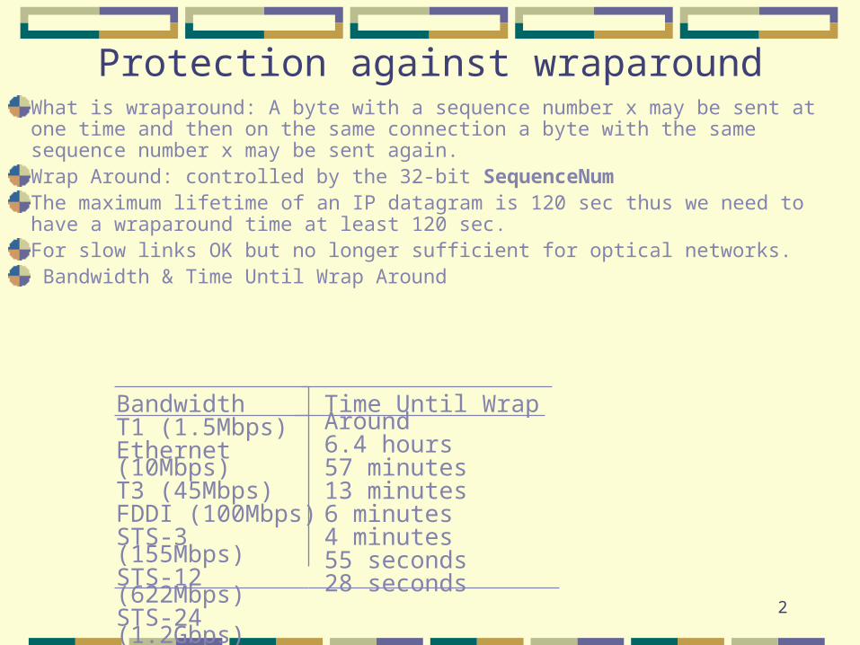
Protection against wraparoundWhat is wraparound: A byte with a sequence number x may be sent at one time and then on the same connection a byte with the same sequence number x may be sent again.Wrap Around: controlled by the 32-bit SequenceNumThe maximum lifetime of an IP datagram is 120 sec thus we need to have a wraparound time at least 120 sec.For slow links OK but no longer sufficient for optical networks. Bandwidth & Time Until Wrap Around
BandwidthT1 (1.5Mbps)Ethernet (10Mbps)T3 (45Mbps)FDDI (100Mbps)STS-3 (155Mbps)STS-12 (622Mbps)STS-24 (1.2Gbps)
Time Until Wrap Around6.4 hours57 minutes13 minutes6 minutes4 minutes55 seconds28 seconds

3
Keeping the pipe full
The SequenceNum, the sequence number space (32 bits) should be twice as large as the window size (16 bits). It is.
The window size (the number of bytes in transit) is given by the the AdvertisedWindow field (16 bits).
The higher the bandwidth the larger the window size to keep
the pipe full.Essentially we regard the network as a storage system and the amount of data is equal to: ( bandwidth x delay )

4
Required window size for a 100 msec RTT.
BandwidthT1 (1.5Mbps)Ethernet (10Mbps)T3 (45Mbps)FDDI (100Mbps)STS-3 (155Mbps)STS-12 (622Mbps)STS-24 (1.2Gbps)
Delay x Bandwidth Product18KB122KB549KB1.2MB1.8MB7.4MB14.8MB

5
Original Algorithm for Adaptive Retransmission
Measure SampleRTT for each segment/ACK pair Compute weighted average of RTTEstimatedRTT = x EstimatedRTT + (1- x SampleRTT
where 0.8 < 0.9
Set timeout based on EstimatedRTT TimeOut = 2 x EstimatedRTT

6
Karn/Partridge Algorithm
Do not sample RTT when re-transmitting
Double timeout after each retransmission

7
Karn/Partridge Algorithm
Sender SenderReceiver Receiver
Sample RTT
O rig ina l transm ission
R e-transm ission
A cknow ledgm ent
O rig ina l transm ission
A cknow ledgm ent
R e-transm ission
Sample RTT

8
Jacobson/Karels Algorithm
New calculation for average RTTDiff = SampleRTT - EstimatedRTT EstimatedRTT = EstimatedRTT + ( x Deviation = Deviation + (|Diff|- Deviation) where is a fraction between 0 and 1
Consider variance when setting timeout value TimeOut = x EstimatedRTT + x Deviation where = 1 and = 4
Notes algorithm only as good as granularity of clock (500
microseconds on Unix) accurate timeout mechanism important to congestion
control (later)

9
Congestion Control Mechanisms
The sender must perform retransmissions to compensate for lost packets due to buffer overflow.Unneeded retransmissions by the sender due to large delays causes a router to use link bandwidth to forward unneeded copies of a packet.
When a packet is dropped along a path the capacity used used at each upstream routers to forward packets to the point where it was dropped was wasted.

10
Delay/Throughput Tradeoffs Q uality o f S ervice
(D e lay)
Q uantity o f S ervice(Throughput)

11
1
2
3
4
5
6
7
8
9
10
11
12
13
1 2 3 4 5 6 7 8 9 10 11 12
threshold
new threshold
time
timeout occurs
slowstart
window size
congestionavoidance

12
Router with infinite buffer capacity
H ost A
H ost B
R outerinl
inl
outl
inl
outl
C
C/2
C/2
inlC/2
D elay
13
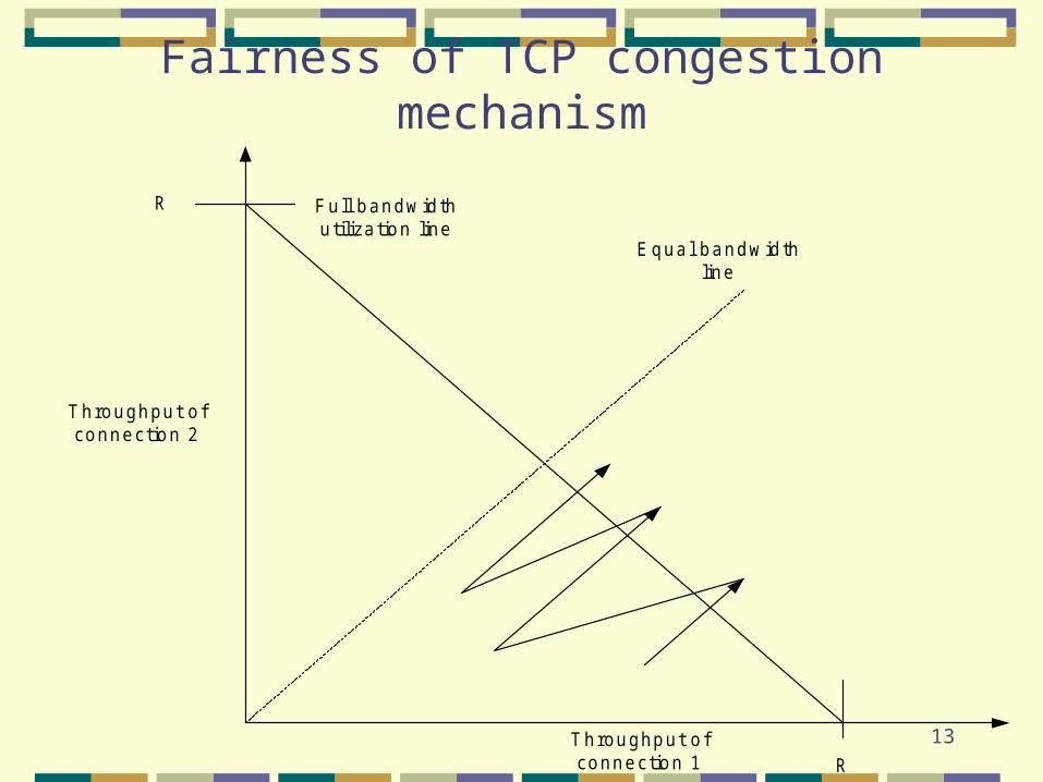
Fairness of TCP congestion mechanism
Equal bandwidthline
Fu ll bandw idthutiliza tion line
Throughput o fconnection 1
Throughput o fconnection 2
R
R

14
Flows and resource allocation
Flow: sequence of packets with a common characteristics
A layer-N flow the common attribute a layer-N attributeAll packets exchanged between two hosts
network layer flow All packets exchanged between two
processes transport layer flow

15
who makes decisions
host-centric
router-centric
basis fordecisions
the needs of the flow
the state of network
how are decisionsenforced

16
Min-max fair bandwidth allocation
Goal: fairness in a best-effort network.
Consider:Unidirectional flowsRouters with infinite buffer space
Link capacity is the only limiting factor.

17
AlgorithmStart with an allocation of zero Mbps for each flow.Increment equally the allocation for each flow until one of the links of the network becomes saturated. Now all the flows passing through the saturated link get an equal fraction of the link capacity.Increment equally the allocation for each flow that does not pass through the first saturated link until a second link becomes saturated. Now all the flows passing through the saturated link get an equal fraction of the link capacity.Continue by incrementing equally the allocations of all flows that do not use a saturated link until all flows use at least one saturated link.

18
QoS in a datagram network?
Buffer acceptance algorithms.
Explicit Congestion Notification.
Packet Classification.
Flow measurements

19
Buffer acceptance algorithms
Tail Drop.
RED – Random Early Detection
RIO – Random Early Detection with In and Out packet dropping strategies.

20
1.0
maxDropProb
minThr_out maxThr_out
minThr_in maxThr_in
avgQue
minThr_inmaxThr_in
sampleQueueLength
dropProb
low load
maxThr_out minThr_out
low load
medium load
medium load
high load
high load
out
in
(a)
(b)sampleQueueLength
inout

21
Explicit Congestion Notification (ECN) The TCP congestion control mechanism discussed earlier has a major flow; it detects congestion after the routers have already started dropping packets. Network resources are wasted because packets are dropped at some point along their path, after using link bandwidth as well as router buffers and CPU cycles up to the point where they are discharged.The question that comes to mind is: Could routers prevent congestion by informing the source of the packets when they become lightly congested, but before they start dropping packets? This strategy is called source quench.

22
Source quench
Send explicit notifications to the source, e.g., use the ICMP. Yet, sending more packets in a network that shows signs of congestion may not be the best idea.
Modify a congestion notification flag in the IP header to inform the destination; then have the destination inform the source by setting a flag in the TCP header of segments carrying acknowledgments.

23
Problems with ECN
(1) TCP must be modified to support the new flag.
(2) Routers must be modified to distinguish between ECN-capable flows and those who do not support ECN.
(3) IP must be modified to support the congestion notification flag.
(4) TCP should allow the sender to confirm the congestion notification to the receiver, because acknowledgments could be lost.

24
Maximum and minimum bandwidth guarantees
A. Packet classification. Identify the flow the packet belongs to. At what layer should be done? Network layer? At each router too expensive. The edge routers may be able to do that. At application layer? Difficult. MPLS – multi protocol label switch. Add an extra header
in front of the IP header. Now a router decides the output link based upon the input link and the MPLS header.

25
Maximum and minimum bandwidth guarantees
B. Flow measurementsHow to choose the measurement interval to
accommodate bursty traffic?Token bucket

26
The token bucket filter
Characterized by : (1) A token rate R, and (2) The depth of the bucket, B
Basic idea the sender is allocated tokens at a given rate and can accumulate tokens in the bucket until the bucket is filled. To send a byte the sender must have a token. The maximum burst can be of size B because at most B token can be accumulated.
27
Example
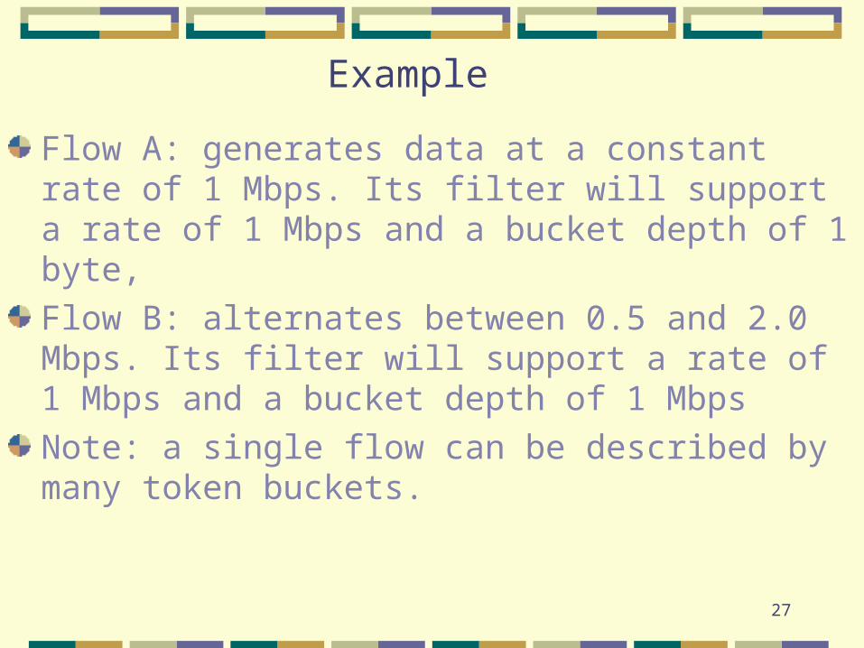
Flow A: generates data at a constant rate of 1 Mbps. Its filter will support a rate of 1 Mbps and a bucket depth of 1 byte,
Flow B: alternates between 0.5 and 2.0 Mbps. Its filter will support a rate of 1 Mbps and a bucket depth of 1 Mbps
Note: a single flow can be described by many token buckets.

28
Example
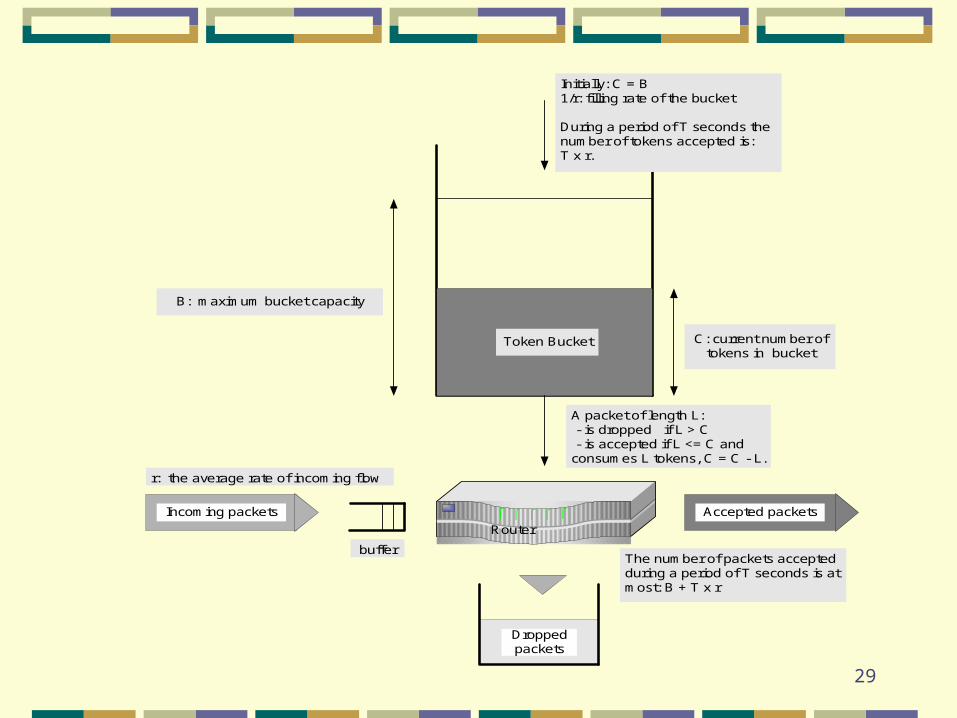
29
B: maximum bucket capacity
C: current number oftokens in bucket
Token Bucket
Router
Incoming packets Accepted packets
Droppedpackets
Initially: C = B1/r: filling rate of the bucket
During a period of T seconds thenumber of tokens accepted is:T x r.
r: the average rate of incoming flow
The number of packets acceptedduring a period of T seconds is atmost: B + T x r
A packet of length L: - is dropped if L > C - is accepted if L <= C andconsumes L tokens, C = C - L.
buffer

30
Token bucket
L = packet lengthC = # of tokens in the bucket---------------------------------------------------if ( L <= C ) { accept the packet; C = C - L; }else drop the packet;

31
A shaping buffer delays packets that do not confirm to the traffic shape
if ( L <= C ) {
accept the packet;
C = C - L;}
else { /* the packet arrived early, delay it */
while ( C < L ) {
wait; }
transmit the packet;
C = C - L;}

32
A QoS Capable Router
Shaper
Policer
Classifier
Outputlink
Inputflows
Dispatcherand Buffer
Acceptance