
1 Introductory Lecture Series: The Anesthesia Machine DR. ALI AMMAR DR. TAHIR MALIK.
36
1 Introductory Lecture Series: The Anesthesia Machine DR. ALI AMMAR DR. TAHIR MALIK
-
Upload
zoe-higgins -
Category
Documents
-
view
222 -
download
3
Transcript of 1 Introductory Lecture Series: The Anesthesia Machine DR. ALI AMMAR DR. TAHIR MALIK.
1
Introductory Lecture Series: The Anesthesia Machine
DR. ALI AMMARDR. TAHIR MALIK

2
Objectives
Anesthesia Machine Ventilators Scavenging Systems System Checkout

3
vaporizerbellow
Corrugated tube
Soda lime
Flow meter
ventilator
APL valve
Scavenging system
4
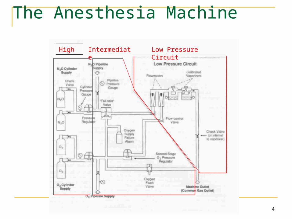
The Anesthesia Machine
High Intermediate Low Pressure Circuit

5
High Pressure System
Receives gasses from the high pressure E cylinders attached to the back of the anesthesia machine (2200 psig for O2, 745 psig for N2O)
Consists of: Hanger Yolk (reserve gas cylinder holder) Check valve (prevent reverse flow of gas) Cylinder Pressure Indicator (Gauge) Pressure Reducing Device (Regulator)
Usually not used, unless pipeline gas supply is off
6
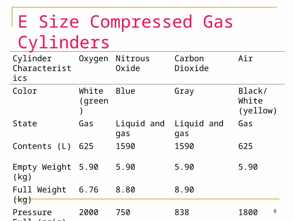
E Size Compressed Gas Cylinders
Cylinder Characteristics
Oxygen Nitrous Oxide Carbon Dioxide Air
Color White (green)
Blue Gray Black/White (yellow)
State Gas Liquid and gas
Liquid and gas Gas
Contents (L) 625 1590 1590 625
Empty Weight (kg)
5.90 5.90 5.90 5.90
Full Weight (kg) 6.76 8.80 8.90
Pressure Full (psig)
2000 750 838 1800

7
Hanger Yolk
Hanger Yolk: orients and supports the cylinder, providing a gas-tight seal and ensuring a unidirectional gas flow into the machine
Index pins: Pin Index Safety System (PISS) is gas specificprevents accidental rearrangement of cylinders (e.g.. switching O2 and N2O)

8
Pressure Reducing Device
Reduces the high and variable pressures found in a cylinder to a lower and more constant pressure found in the anesthesia machine (45 psig)
Reducing devices are preset so that the machine uses only gas from the pipeline (wall gas), when the pipeline inlet pressure is 50 psig.
This prevents gas use from the cylinder even if the cylinder is left open (i.e. saves the cylinder for backup if the wall gas pipeline fails)
9
Pressure Reducing Device
Cylinders should be kept closed routinely. Otherwise, if the wall gas fails, the machine will automatically switch to the cylinder supply without the anesthetist being aware that the wall supply has failed (until the cylinder is empty too).
10
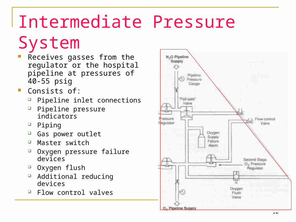
Intermediate Pressure System Receives gasses from the
regulator or the hospital pipeline at pressures of 40-55 psig
Consists of: Pipeline inlet connections Pipeline pressure indicators Piping Gas power outlet Master switch Oxygen pressure failure
devices Oxygen flush Additional reducing devices Flow control valves

11
Pipeline Inlet Connections
Mandatory N2O and O2, usually have air and suction too
Inlets are non-interchangeable due to specific threading as per the Diameter Index Safety System (DISS)
Each inlet must contain a check valve to prevent reverse flow (similar to the cylinder yolk)
12
Oxygen Pressure Failure Devices Machine standard requires that an anesthesia machine be
designed so that whenever the oxygen supply pressure is reduced below normal, the oxygen concentration at the common gas outlet does not fall below 19%

13
Oxygen Pressure Failure Devices A Fail-Safe valve is present in the gas line supplying
each of the flowmeters except O2. This valve is controlled by the O2 supply pressure and shuts off or proportionately decreases the supply pressure of all other gasses as the O2 supply pressure decreases
Historically there are 2 kinds of fail-safe valves Pressure sensor shut-off valve (Ohmeda) Oxygen failure protection device (Drager)

14
Pressure Sensor Shut-Off Valve
Oxygen supply pressure opens the valve as long as it is above a pre-set minimum value (e.g.. 20 psig).
If the oxygen supply pressure falls below the threshold value the valve closes and the gas in that limb (e.g.. N2O), does not advance to its flow-control valve.

15
Oxygen Failure Protection Device (OFPD) Based on a proportioning principle rather than a shut-off
principle The pressure of all gases controlled by the OFPD will
decrease proportionately with the oxygen pressure

16
Oxygen Supply Failure Alarm
The machine standard specifies that whenever the oxygen supply pressure falls below a manufacturer-specified threshold (usually 30 psig) a medium priority alarm shall blow within 5 seconds.

17
Limitations of Fail-Safe Devices/Alarms Fail-safe valves do not prevent administration of a
hypoxic mixture because they depend on pressure and not flow.
These devices do not prevent hypoxia from accidents such as pipeline crossovers or a cylinder containing the wrong gas
18
Limitations of Fail-Safe Devices/Alarms These devices prevent hypoxia from some problems
occurring upstream in the machine circuitry (disconnected oxygen hose, low oxygen pressure in the pipeline and depletion of the oxygen cylinder)
Equipment problems that occur downstream (for example leaks or partial closure of the oxygen flow control valve) are not prevented by these devices.
19
Oxygen Flush Valve (O2+)
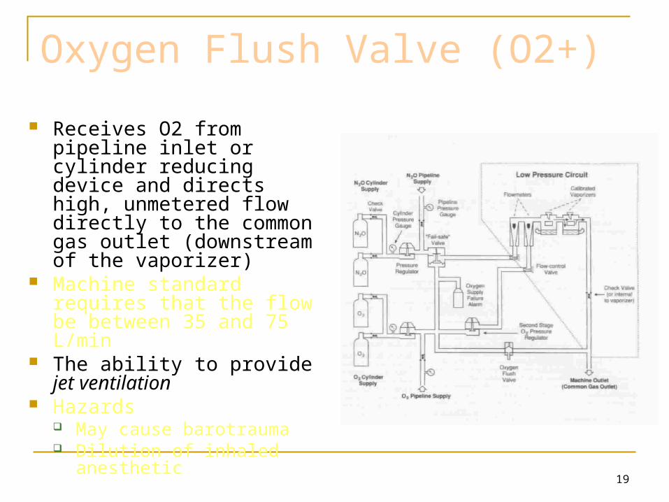
Receives O2 from pipeline inlet or cylinder reducing device and directs high, unmetered flow directly to the common gas outlet (downstream of the vaporizer)
Machine standard requires that the flow be between 35 and 75 L/min
The ability to provide jet ventilation
Hazards May cause barotrauma Dilution of inhaled anesthetic

20
Second-Stage Reducing Device Located just upstream of the flow control
valves Receives gas from the pipeline inlet or the
cylinder reducing device and reduces it further to 26 psig for N2O and 14 psig for O2
Purpose is to eliminate fluctuations in pressure supplied to the flow indicators caused by fluctuations in pipeline pressure

21
Low Pressure System
Extends from the flow control valves to the common gas outlet
Consists of: Flow meters Vaporizer mounting device Check valve Common gas outlet

22
Flowmeter assembly
When the flow control valve is opened the gas enters at the bottom and flows up the tube elevating the indicator
The indicator floats freely at a point where the downward force on it (gravity) equals the upward force caused by gas molecules hitting the bottom of the float

23
Arrangement of the Flow-Indicator Tubes
In the presence of a flowmeter leak (either at the “O” ring or the glass of the flow tube) a hypoxic mixture is less likely to occur if the O2 flowmeter is downstream of all other flowmeters
In A and B a hypoxic mixture can result because a substantial portion of oxygen flow passes through the leak, and all nitrous oxide is directed to the common gas outlet
* Note that a leak in the oxygen flowmeter tube can cause a hypoxic mixture, even when oxygen is located in the downstream position

24
Proportioning Systems
Mechanical integration of the N2O and O2 flow-control valves
Automatically intercedes to maintain a minimum 25% concentration of oxygen with a maximum N2O:O2 ratio of 3:1

25
Limitations of Proportioning Systems Machines equipped with proportioning systems can
still deliver a hypoxic mixture under the following conditions: Wrong supply gas Defective pneumatics or mechanics (e.g.. The Link-25
depends on a properly functioning second stage regulator) Leak downstream (e.g.. Broken oxygen flow tube) Inert gas administration: Proportioning systems generally
link only N2O and O2

26
Vaporizers
A vaporizer is an instrument designed to change a liquid anesthetic agent into its vapor and add a controlled amount of this vapor to the fresh gas flow

27
Classification of Vaporizers
Methods of regulating output concentration
Concentration calibrated (e.g. variable bypass)
Measured flowMethod of vaporization
Flow-over
Bubble through
InjectionTemperature compensation
Thermocompensation
Supplied heat
28
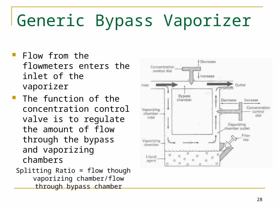
Generic Bypass Vaporizer
Flow from the flowmeters enters the inlet of the vaporizer
The function of the concentration control valve is to regulate the amount of flow through the bypass and vaporizing chambers
Splitting Ratio = flow though vaporizing chamber/flow through bypass
chamber
29
Factors That Influence Vaporizer Output
Flow Rate: The output of the vaporizer is generally less than the dial setting at very low (< 200 ml/min) or very high (> 15 L/min) flows
Temperature: Automatic temperature compensating mechanisms in bypass chambers maintain a constant vaporizer output with varying temperatures
Back Pressure: Intermittent back pressure (e.g. positive pressure ventilation causes a higher vaporizer output than the dial setting)

30
Factors That Influence Vaporizer Output Atmospheric Pressure: Changes in atmospheric
pressure affect variable bypass vaporizer output as measured by volume % concentration, but not (or very little) as measured by partial pressure (lowering atmospheric pressure increases volume % concentration and vice versa)
Carrier Gas: Vaporizers are calibrated for 100% oxygen. Carrier gases other than this result in decreased vaporizer output.

31
The Circuit: Circle System
Arrangement is variable, but to prevent re-breathing of CO2, the following rules must be followed: Unidirectional valves between
the patient and the reservoir bag
Fresh-gas-flow cannot enter the circuit between the expiratory valve and the patient
Adjustable pressure-limiting valve (APL) cannot be located between the patient and the inspiratory valve

32
Circle System
Advantages: Relative stability of inspired concentration Conservation of respiratory moisture and heat Prevention of operating room pollution PaCO2 depends only on ventilation, not fresh gas
flow Low fresh gas flows can be used
Disadvantages: Complex design = potential for malfunction High resistance (multiple one-way valves) = higher
work of breathing
33
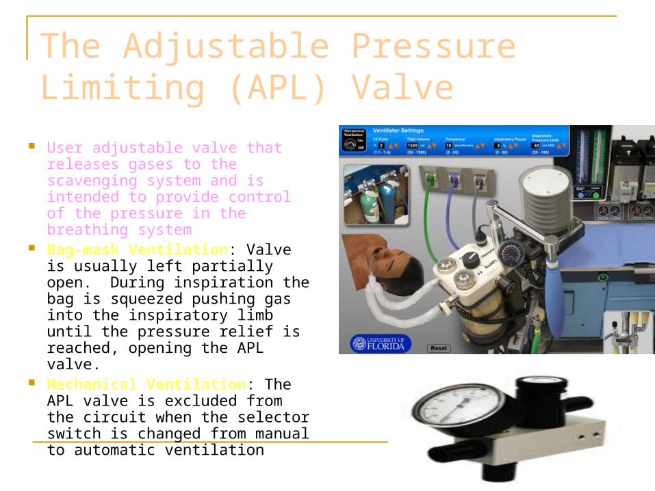
The Adjustable Pressure Limiting (APL) Valve
User adjustable valve that releases gases to the scavenging system and is intended to provide control of the pressure in the breathing system
Bag-mask Ventilation: Valve is usually left partially open. During inspiration the bag is squeezed pushing gas into the inspiratory limb until the pressure relief is reached, opening the APL valve.
Mechanical Ventilation: The APL valve is excluded from the circuit when the selector switch is changed from manual to automatic ventilation

34
Scavenging Systems
Protects the breathing circuit or ventilator from excessive positive or negative pressure.

35
Scavenging Systems

36
Checking Anesthesia Machines
8 Categories of check: Emergency ventilation equipment High-Pressure system Low-Pressure system Scavenging system Breathing system Manual and automatic ventilation system Monitors Final Position