1 Introduction to Modeler © copyright 2004 OPNET Technologies, Inc.
53
1 Introduction to Modeler © copyright 2004 OPNET Technologies, Inc.
-
date post
22-Dec-2015 -
Category
Documents
-
view
222 -
download
0
Transcript of 1 Introduction to Modeler © copyright 2004 OPNET Technologies, Inc.
1
Introduction to Modeler
© copyright 2004 OPNET Technologies, Inc.

2
Introduction to Modeler
© copyright 2004 OPNET Technologies, Inc.
What is Modeler?
• An environment for building protocols and device models.
• An environment to plan changes by illustrating how the networked environment will perform.
• An environment that includes hundreds of pre-built models, used to study performance changes of your network: organizational scaling, technology changes, and application deployment.

3
Introduction to Modeler
© copyright 2004 OPNET Technologies, Inc.
Modeler Demo
• Network Models• Represent data networks
• Run simulations on network
• Node Models• Model devices in the network
• Process Models• Represent communications protocols, CPUs, queuing schemes, etc.
• Other editors discussed later in course

4
Introduction to Modeler
© copyright 2004 OPNET Technologies, Inc.

5
Introduction to Modeler
© copyright 2004 OPNET Technologies, Inc.
Overview
• Project Editor:• Workflow• More Details of the Project Workspace
• Map Backgrounds• Zooming• Threshold Value• Annotation Palette• Project Workspace {Lab}
• Models• Deriving and Creating New Devices {Lab}
• Object Attributes• Client-Server Configuration Example
• Statistics• Product Documentation
6
Introduction to Modeler
© copyright 2004 OPNET Technologies, Inc.
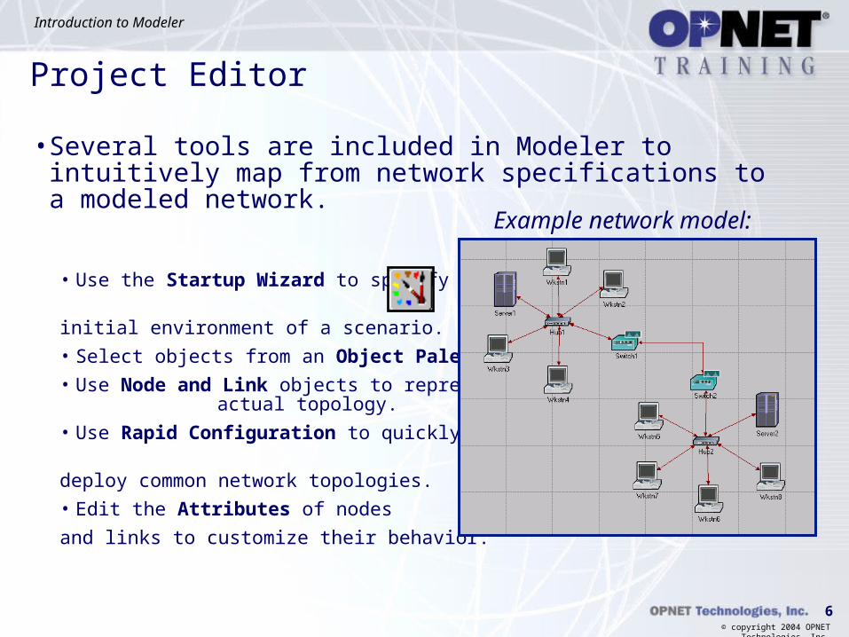
Project Editor
• Several tools are included in Modeler to intuitively map from network specifications to a modeled network.
• Use the Startup Wizard to specify the
initial environment of a scenario.
• Select objects from an Object Palette.
• Use Node and Link objects to represent actual topology.
• Use Rapid Configuration to quickly
deploy common network topologies.
• Edit the Attributes of nodes
and links to customize their behavior.
Example network model:

7
Introduction to Modeler
© copyright 2004 OPNET Technologies, Inc.
• Note that several maps can overlay each other.
• View/hide maps by choosing View / Set Background Properties
• Geotiff images automatically appear at the correct latitude and longitude position.
Setting Background Maps

8
Introduction to Modeler
© copyright 2004 OPNET Technologies, Inc.
Zoom In / Zoom Out• Zooming in and out allows you to magnify the network in the
workspace.
• This may be for display purposes or to emphasize a particular portion of the model.
Notice the difference in detail.

9
Introduction to Modeler
© copyright 2004 OPNET Technologies, Inc.
Changing Icon Size
• You can scale the size of an icon on the screen to improve the appearance of the topology
• View / Scale Selected Icons…

10
Introduction to Modeler
© copyright 2004 OPNET Technologies, Inc.
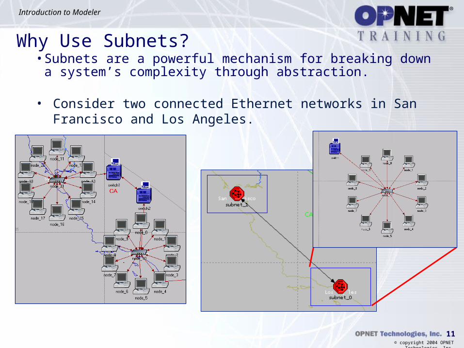
• A subnetwork abstracts network components specified within it into a single object.
• Subnetworks:• Represent identical constructs in an actual
network.
• Have no behavioral aspects, but simplify representation of large networks.
• May be stationary or mobile.
• Subnets can be used to segment networks into distinct
parts based on proximity, connectivity, or architecture
3 Subnet Types
Subnets
11
Introduction to Modeler
© copyright 2004 OPNET Technologies, Inc.
Why Use Subnets?• Subnets are a powerful mechanism for breaking down a system’s
complexity through abstraction.
• Consider two connected Ethernet networks in San Francisco and Los Angeles.

12
Introduction to Modeler
© copyright 2004 OPNET Technologies, Inc.
Model Library Components
• The “Model Library” contains a variety of objects used for creating networks
• Traffic generators (workstations, servers, stations, etc.)• Network devices (hubs, bridges, switches, routers, etc.)• Links (SONET, PPP, FDDI, 10BaseT, ISDN, xDSL, etc.)• Vendor device models (Cisco Systems, 3Com, Nortel, Lucent, HP, etc.)
• These models are ready-to-use to create networks and predict performance behavior.

13
Introduction to Modeler
© copyright 2004 OPNET Technologies, Inc.
Model Libraries Available
• OPNET Model Libraries• Standard Model Library
• Essential models that support the majority of OPNET modeling users.• Comes with the software.
• Vendor Model Library• Extensive library of pre-built vendor device models.
• Specialized Model Library• Models of interest to more focused communities within the OPNET user base.• These models correspond to emerging or vendor-specific technologies.• They are available on a fee/license basis.• Current specialized models.
• Circuit-switched / SS7-Server Modeling• IP Multicasting -DOCSIS• MPLS -UMTS• PNNI -IPv6
14
Introduction to Modeler
© copyright 2004 OPNET Technologies, Inc.
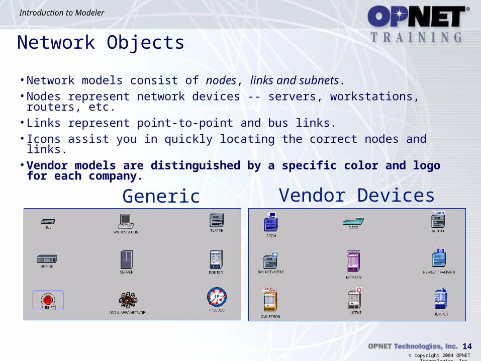
Network Objects
• Network models consist of nodes, links and subnets.• Nodes represent network devices -- servers, workstations, routers, etc.• Links represent point-to-point and bus links.• Icons assist you in quickly locating the correct nodes and links.• Vendor models are distinguished by a specific color and logo for each
company.
Generic Devices Vendor Devices

15
Introduction to Modeler
© copyright 2004 OPNET Technologies, Inc.
Model Naming Convention
• OPNET’s standard model suite uses a specific naming convention for its node models:
<protocoln>…<protocoln >_<function>_<modifier>
• <protocoln> is an abbreviation that specifies a particular protocol that is supported within the model. The variable n represents the number of protocol interfaces within that model.
• <function> is an abbreviation that indicates the general function of the node, e.g. gateway, workstation, server.
• Levels of derivation (<modifier> value)• adv: advanced model. All node attributes are available and attribute values are set to their
defaults.• int: intermediate model. Attributes that are unlikely to be changed are hidden and typical
values are applied to the visible attributes.• Models with no value for modifier are derived from intermediate models. Additional
attributes are hidden and only attributes needed for parametric studies are visible.

16
Introduction to Modeler
© copyright 2004 OPNET Technologies, Inc.
Vendor Models• Naming convention for vendor models
<Vendor_Name>_<Device_Name>_<Number_of_Slots>_<Configuration>
Example: CS_4000_3s_e6_f_fr2_sl2
This model represents a Cisco Systems 4000 Router with 3 slots, 6 ethernet ports, 1 FDDI port, 2 frame relay ports, and 2 SL-IP ports.
• View description of the node by:• Right-clicking on the
node in the object palette.
• Right-clicking on the node in the workspace and selecting “View Node Description”.

17
Introduction to Modeler
© copyright 2004 OPNET Technologies, Inc.
Creating New Devices
• Although OPNET Modeler includes hundreds of standard and vendor devices, you may need to customize models.
• There are several ways to create new devices or derive models from the existing database to custom specifications.• Two methods discussed here to change and existing model
• Modeling new devices and protocols discussed later in course
18
Introduction to Modeler
© copyright 2004 OPNET Technologies, Inc.
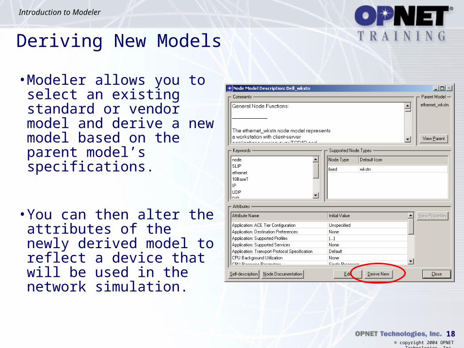
Deriving New Models
• Modeler allows you to select an existing standard or vendor model and derive a new model based on the parent model’s specifications.
• You can then alter the attributes of the newly derived model to reflect a device that will be used in the network simulation.

19
Introduction to Modeler
© copyright 2004 OPNET Technologies, Inc.
Deriving New Models
1
2
3
4
5
6

20
Introduction to Modeler
© copyright 2004 OPNET Technologies, Inc.
21
Introduction to Modeler
© copyright 2004 OPNET Technologies, Inc.
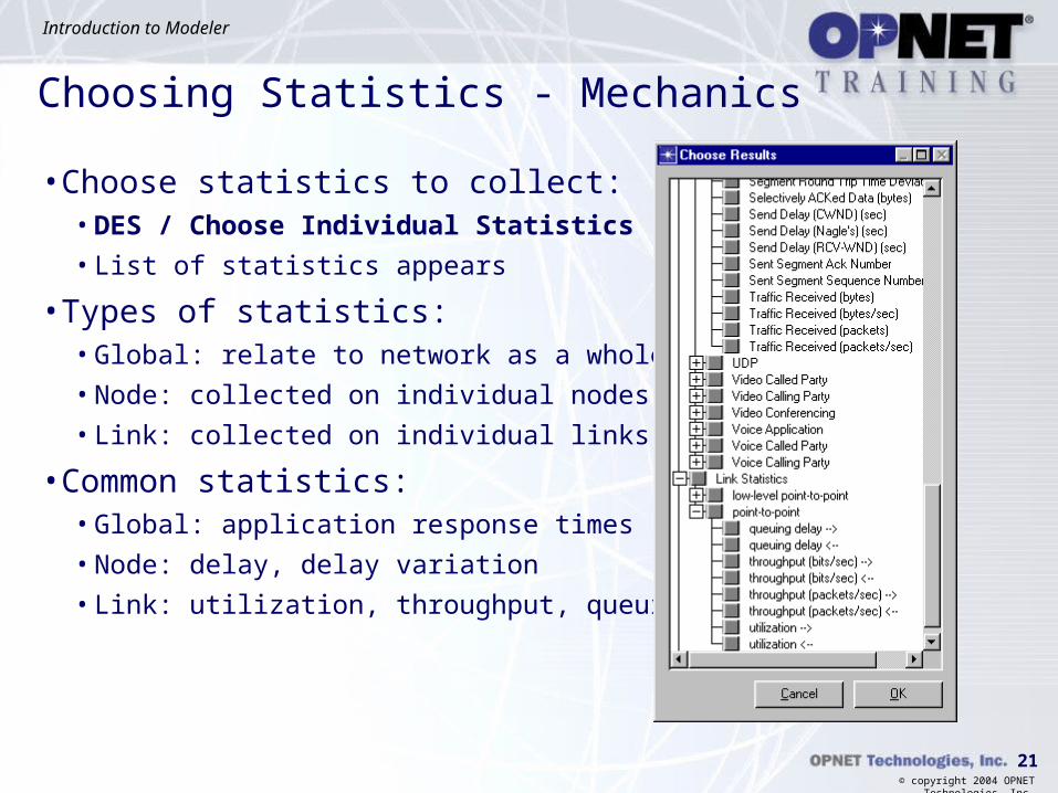
Choosing Statistics - Mechanics
• Choose statistics to collect:• DES / Choose Individual Statistics
• List of statistics appears
• Types of statistics:• Global: relate to network as a whole
• Node: collected on individual nodes
• Link: collected on individual links
• Common statistics:• Global: application response times
• Node: delay, delay variation
• Link: utilization, throughput, queuing delay

22
Introduction to Modeler
© copyright 2004 OPNET Technologies, Inc.
Statistic Collection Modes
• There are three types of statistic collection modes
• All values mode: Every data point is collected from a statistic.
• Sample mode: The data is collected according to a user-defined time interval or sample count. For example, you could specify that data be collected every 10th simulation second or every 10th data point.
• Bucket mode: All the data points are collected over the time interval or sample count and are processed according to a user-defined parameter-- max, min, sum, count, sample average or time average. (This is the default mode.)

23
Introduction to Modeler
© copyright 2004 OPNET Technologies, Inc.
Simulation Mechanics
• Run simulation• DES / Configure/Run Discrete
Event Simulation
• Set simulation options
• Click Run
• While simulation is running, view stats on events processed per second and amount of RAM used by simulation
• After simulation completes, check simulation log for errors• DES / Open DES Log

24
Introduction to Modeler
© copyright 2004 OPNET Technologies, Inc.
DES Concept – Viewing Results• If simulation log reveals no errors that invalidate results, view results
graphs on statistics you collected• Right-click on workspace / View Results
• View list of node/link statistics in order from highest to lowest• Ex: View most utilized links
• Right-click on workspace / Find Top Results
• Compare results between multiple scenarios on same graph• Right-click on workspace / Compare Results

25
Introduction to Modeler
© copyright 2004 OPNET Technologies, Inc.
Results Options
• Stacked Statistics
• Overlaid Statistics

26
Introduction to Modeler
© copyright 2004 OPNET Technologies, Inc.

27
Introduction to Modeler
© copyright 2004 OPNET Technologies, Inc.
• Conceptual Goals• Objects available in the modeling domains
• Data transfer between objects in a simulation
• Network, node, and process models
• Object attributes
• Object naming paradigm
• Role of packets in a simulation
Agenda

28
Introduction to Modeler
© copyright 2004 OPNET Technologies, Inc.
Network Objects - Links• Link objects model physical layer effects between nodes, such as
delays, noise, etc.
A wireless link, established during a simulation, can be created between any radio transmitter-receiver channel pair. Satellite and mobile nodes must use wireless links. Fixed nodes may use wireless links. A wireless link is not drawn but is established if nodes contain radio transceivers.
A bus link transfers data among many nodes and is a shared media.
A point-to-point link transfers data between two fixed nodes.
Wireless link
29
Introduction to Modeler
© copyright 2004 OPNET Technologies, Inc.
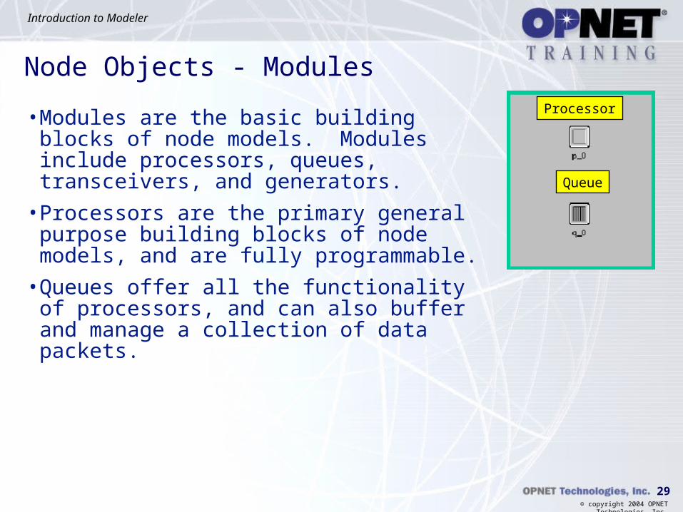
Node Objects - Modules
• Modules are the basic building blocks of node models. Modules include processors, queues, transceivers, and generators.
• Processors are the primary general purpose building blocks of node models, and are fully programmable.
• Queues offer all the functionality of processors, and can also buffer and manage a collection of data packets.
Processor
Queue

30
Introduction to Modeler
© copyright 2004 OPNET Technologies, Inc.
Transmitters and Receivers
• Transmitters are the outbound interfaces between objects inside a node and communication links outside it.
• Receivers are the inbound interface.

31
Introduction to Modeler
© copyright 2004 OPNET Technologies, Inc.
Transmitters and Receivers
• Three types of transmitter and receiver modules correspond to different models of communication links.
• Antennas may be used with radio transceivers to specify antenna properties.
Bus transceiversPoint-to-point transceivers Packet radio transceivers
Transmitter Receiver Transmitter Receiver Transmitter Receiver
Antenna

32
Introduction to Modeler
© copyright 2004 OPNET Technologies, Inc.
Module Connections
• Packet streams carry data packets from a source to a destination module.
• Statistic wires carry a single data value from a source to a destination module. In this case, hub_rx0 might report a packet reception to mac.

33
Introduction to Modeler
© copyright 2004 OPNET Technologies, Inc.
Sample Node Model
• Node models support
• Layering of protocol functions
• Dynamic inter-module monitoring
• Arbitrary node architectures
• Definition of node classes through attribute promotion
ethernet_wkstn_adv Node Model

34
Introduction to Modeler
© copyright 2004 OPNET Technologies, Inc.
Process Model Objects - States
• The initial state is the place where execution begins in a process.
• A forced state does not allow a pause during the process.
• An unforced state allows a pause during the process.
• Later chapters will fully discuss the differences between these types of states.
Initial state Forced state Unforced state
red redgreen

35
Introduction to Modeler
© copyright 2004 OPNET Technologies, Inc.
State Connections - Transitions
• Transitions describe the possible movement of a process from state to state and the conditions allowing such a change.
• Exactly one condition must evaluate to true.
• If the condition statement (x == y) is true, the transition executive (Reset_Timers;) is invoked.
Transition executiveCondition statement

36
Introduction to Modeler
© copyright 2004 OPNET Technologies, Inc.
Executive Blocks
• Each state has two executive blocks• Enter executives are invoked on entering a state.
• Exit executives are invoked before exiting a state.

37
Introduction to Modeler
© copyright 2004 OPNET Technologies, Inc.
Kernel Procedures - Introduction• KPs are pre-written functions that abstract difficult, tedious, or
common operations. KPs free you from addressing memory management, data structure, handling event processing, etc.
• All KPs begin with prefix “op_”.
• KPs focus on communication modeling.
38
Introduction to Modeler
© copyright 2004 OPNET Technologies, Inc.
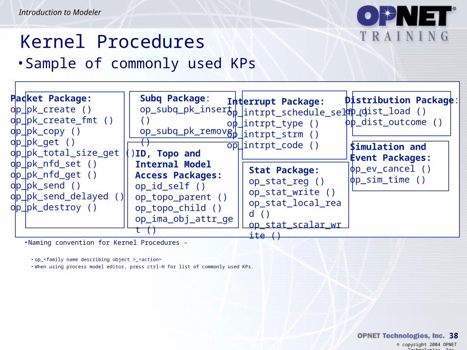
Kernel Procedures
Packet Package:op_pk_create ()op_pk_create_fmt ()op_pk_copy ()op_pk_get ()op_pk_total_size_get ()op_pk_nfd_set ()op_pk_nfd_get ()op_pk_send ()op_pk_send_delayed ()op_pk_destroy ()
Subq Package:op_subq_pk_insert ()op_subq_pk_remove ()
Stat Package:op_stat_reg ()op_stat_write ()op_stat_local_read ()op_stat_scalar_write ()
Interrupt Package:op_intrpt_schedule_self ()op_intrpt_type ()op_intrpt_strm ()op_intrpt_code () Simulation and
Event Packages:op_ev_cancel ()op_sim_time ()
ID, Topo and Internal Model Access Packages:op_id_self ()op_topo_parent ()op_topo_child ()op_ima_obj_attr_get ()
Distribution Package:op_dist_load ()op_dist_outcome ()
• Sample of commonly used KPs
• Naming convention for Kernel Procedures -
• op_<family name describing object >_<action>
• When using process model editor, press ctrl-H for list of commonly used KPs.
39
Introduction to Modeler
© copyright 2004 OPNET Technologies, Inc.
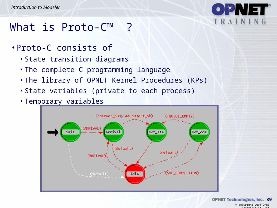
• Proto-C consists of• State transition diagrams
• The complete C programming language
• The library of OPNET Kernel Procedures (KPs)
• State variables (private to each process)
• Temporary variables
What is Proto-C™ ?

40
Introduction to Modeler
© copyright 2004 OPNET Technologies, Inc.
Object Attributes• Attributes are parameters of an object that can configure its behavior.
• Attributes are dynamically changeable during simulation.
• Processes have access to all object attributes.
• Different attribute values allow objects of the same type to behave differently.

41
Introduction to Modeler
© copyright 2004 OPNET Technologies, Inc.
Object Attributes
Though you use the same process model, by changing the data rate for the channel attribute you alter the behavior of the node.
42
Introduction to Modeler
© copyright 2004 OPNET Technologies, Inc.
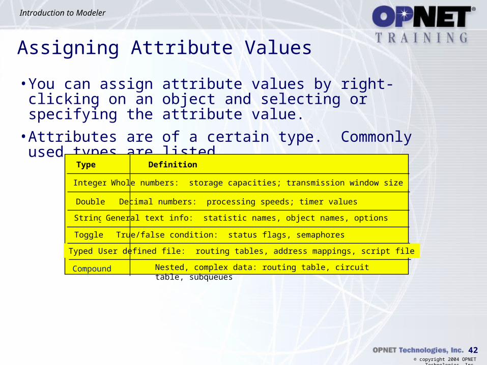
Assigning Attribute Values
• You can assign attribute values by right-clicking on an object and selecting or specifying the attribute value.
• Attributes are of a certain type. Commonly used types are listed.
Type Definition
Integer Whole numbers: storage capacities; transmission window size
Double Decimal numbers: processing speeds; timer values
String General text info: statistic names, object names, options
Toggle True/false condition: status flags, semaphores
Typed file User defined file: routing tables, address mappings, script file
Nested, complex data: routing table, circuit table, subqueuesCompound

43
Introduction to Modeler
© copyright 2004 OPNET Technologies, Inc.
Promoting Attribute Values
• You can “promote” an attribute. This means that you assign a value at a higher hierarchical level.
• Passing control of a lower-level object to a higher level provides more flexibility in how objects are used.
• You can leave an attribute unspecified at even the network level, and assign a value at run time.

44
Introduction to Modeler
© copyright 2004 OPNET Technologies, Inc.
Promoting Attributes Example
• When an attribute assignment is made, promotion stops. An attribute value was assigned at mktg_lan, so the attribute does not appear in the object corporate.
• Attribute names are used as prefixes at each new level of the object hierarchy.
buf
router
mktg_lan
priority has been promoted from buf and set at mktg_lan
buf.priority: promoted
priority: promoted
router.buf.priority: high
corporate

45
Introduction to Modeler
© copyright 2004 OPNET Technologies, Inc.
Model Hierarchy
• The internal structure and behavior of each node is dictated by the node model, specified in the model attribute. The node model is created in the Node Editor.

46
Introduction to Modeler
© copyright 2004 OPNET Technologies, Inc.
Model Hierarchy• The internal structure and behavior of each processor and queue is
dictated by the process model specified in the process model attribute. The process model is created in the Process Editor.
Process model rip_udp_v3

47
Introduction to Modeler
© copyright 2004 OPNET Technologies, Inc.
Object Naming• Each object has a unique name that defines its place in the hierarchy.
• Format of name is:
network_type.subneta.subnetb...subnetz.node_name.
object_name

48
Introduction to Modeler
© copyright 2004 OPNET Technologies, Inc.
Object Naming
full name of generator is usa.dc.opnet.wk9.gen
opnet

49
Introduction to Modeler
© copyright 2004 OPNET Technologies, Inc.
Data Flow Among Objects
• Packets are the basic unit of information exchange in Modeler simulations.
• Information is exchanged among different objects via various communication mechanisms:• Node to node: Links
• Module to module: Packet streams and statistic wires
• State to state: Transitions
50
Introduction to Modeler
© copyright 2004 OPNET Technologies, Inc.
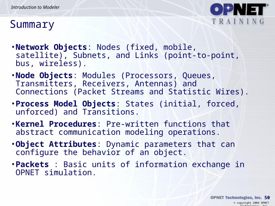
Summary
• Network Objects: Nodes (fixed, mobile, satellite), Subnets, and Links (point-to-point, bus, wireless).
• Node Objects: Modules (Processors, Queues, Transmitters, Receivers, Antennas) and Connections (Packet Streams and Statistic Wires).
• Process Model Objects: States (initial, forced, unforced) and Transitions.
• Kernel Procedures: Pre-written functions that abstract communication modeling operations.
• Object Attributes: Dynamic parameters that can configure the behavior of an object.
• Packets : Basic units of information exchange in OPNET simulation.

51
Introduction to Modeler
© copyright 2004 OPNET Technologies, Inc.
52
Introduction to Modeler
© copyright 2004 OPNET Technologies, Inc.
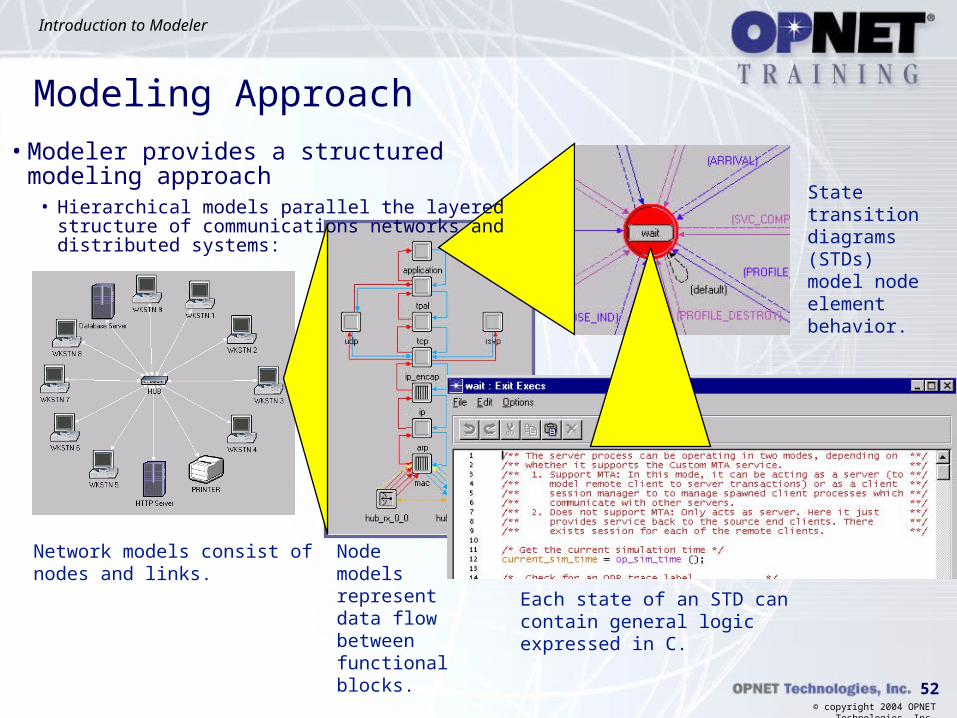
Modeling Approach• Modeler provides a structured modeling approach
• Hierarchical models parallel the layered structure of communications networks and distributed systems:
Node models represent data flow between functional blocks.
Network models consist of nodes and links.
Each state of an STD can contain general logic expressed in C.
State transition diagrams (STDs) model node element behavior.
53
Introduction to Modeler
© copyright 2004 OPNET Technologies, Inc.
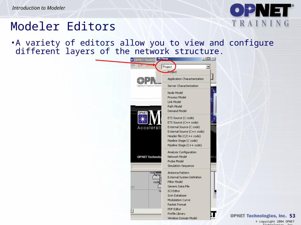
Modeler Editors• A variety of editors allow you to view and configure different layers
of the network structure.


![Automating the Presentation of Computer Networks Automating the Presentation of Computer Networks ... and OPNet Modeler [11]. All of ... Automating the Presentation of Computer Networks](https://static.fdocuments.in/doc/165x107/5b5571c07f8b9a835c8b5502/automating-the-presentation-of-computer-automating-the-presentation-of-computer.jpg)