DN018 -- Range Measurements in an Open Field Environment (Rev. A
Upload
mohammed-raif-melhimCategory
view
220download
0
8/8/2019 1 Introduction to Measurements Systems Rev 7 080215
http://slidepdf.com/reader/full/1-introduction-to-measurements-systems-rev-7-080215 1/15
1 Introduction Measurements & Instrumentation 0908341
© Copyright held by the author 2008: Dr. Lutfi R. Al-Sharif Page 1 of 15
Chapter 1Introduction to Measurement Systems
(Revision 7.0, 15/2/2008)
1. Introduction
Measurement systems have important vital applications in our everyday lives,whether at home, in our vehicles, offices or factories.
We use measuring devices in buying our fruits and vegetables. Weassume that the measuring devices are accurate, and we assume that we areall referring to the same units (e.g., kilogram, metre, litre…). Theconsequence of inaccurate measuring devices in this case leads to financiallosses on our part.
We check the temperature of our homes and assume that thethermostats reading the temperature are accurate. If not, then thetemperature will be either too high or too low, leading to inconvenience anddiscomfort.
We pay for our electricity in units of kWh and we assume that theelectricity metre is accurate and faithfully records the correct number of electricity units that we have used. We pay for the water we consume inlitres, and we also assume that the water meter is correctly measuring theflow of water in litres. In this case as well, the error will lead to financial loss.
The accuracy of the measurement systems mentioned above is veryimportant, but is more critical in some applications than others. For example,a pharmacist preparing a medication is reliant on the accuracy of his/her scales to make sure he/she includes the correct amounts of ingredients in themedication. Another example is the manufacturing of present-day integratedcircuits and photo-masks that requires a high degree of accuracy. Certainchemical reactions require high accuracy in the measurement and control of temperature.
2. Applications of Measurement systemsThe importance of measurement systems is demonstrated by their applicationin our lives. The following are the four main applications of measurementsystems:
1. One of the earliest uses of measurement systems was in regulating trade [1]. For everyday activities such as buying and selling goods, it
is important to have a common standard and to be able to measure itto an appropriate level of accuracy. The main problem was the lack of common standards and unit to use. Even units that had the samename, differed in their actual value. The main two systems thatdominated were the metric and the imperial systems. In scientificapplications the CGS (centimetre-gram-second) and MKS (meter-kilogram-second) systems were also used. This divergence of systems has been addressed in modern times by standardisation,whereby common systems of units and standard references arecommonly recognised and used by all countries, and has culminated inthe adoption of SI units. Thus in addition to regulating trade, the use of
standard units and measures has facilitated the free movement of goods across international boundaries.

8/8/2019 1 Introduction to Measurements Systems Rev 7 080215
http://slidepdf.com/reader/full/1-introduction-to-measurements-systems-rev-7-080215 2/15
1 Introduction Measurements & Instrumentation 0908341
© Copyright held by the author 2008: Dr. Lutfi R. Al-Sharif Page 2 of 15
2. A second application that is widely used in research laboratories is thatof knowledge seeking and problem solving . We use measurements toenhance our knowledge about various systems and understand howdifferent variables interact.
3. Another application is in monitoring functions [1]. In this applicaton weuse measurement systems to inform us of the values of criticalvariables to allow us to take necessary action. We would consult theroom thermometer for example to decide whether to switch the heatingon or off.
4. The fourth application is the use of measurement systems to feed themeasured value to an automatic feedback control systems [1]. In thelast application, the human being was monitoring the value of avariable and taking appropriate action. By closing the loop, the
measurement system becomes part of the automatic feedback controlsystem and this obviates the need for human intervention.
An example is a level measurement system that measures thewater level in a tank and opens a valve to fill it up whenever the water level drops below a certain preset value.
The accuracy and resolution of a measured variable is veryimportant. The control system that uses the output of themeasurement system cannot be more accurate that the accuracy of themeasurement system itself. In effect, a poor measurement systembecomes the weakest link in the control system and causes adeterioration of performance.
3. Elements of a measurement systemEach measurement system consists of five elements. These elements couldall be in one item or could be all in separate five items. They could beadjacent to each other or they could be separated by a distance. Somesimple systems might not contain all of the components. The components of a typical system are shown in Figure 1.

8/8/2019 1 Introduction to Measurements Systems Rev 7 080215
http://slidepdf.com/reader/full/1-introduction-to-measurements-systems-rev-7-080215 3/15
1 Introduction Measurements & Instrumentation 0908341
© Copyright held by the author 2008: Dr. Lutfi R. Al-Sharif Page 3 of 15
Figure 1: Components of a measurement system.
Each of these components is discussed in more detail below.
a. Sensor: The sensor is the element that gives an output that isproportional to the input applied to it. In general the output is inan electrical format as this is the most suitable format for later use (in processing, transmission and storage). The input formatdepends on the variable to be measured (e.g., temperature,pressure, humidity, pH, speed, acceleration, light…). Sensorsusually have a near linear relationship, although this is notalways the case.
b. Signal Conditioning Element (SCE) [2]: This is also referredto sometimes as a variable conversion element [1]: When the
output variable of a primary sensor is in an unsuitable (or inconvenient) format, a signal conditioning element is used toconvert it to a suitable form. For example, the change inresistance of a strain gauge cannot be directly measured andthus a deflection type bridge circuit is used to convert it to asuitable voltage. Bridge circuits are examples of signalconditioning elements and are discussed in more detail in aChapters 11 and 12. Another example is the amplification of avery weak signal such as a biomedical signal (such as that usedin an electrocardiogram ECG, [4] for more details).
The combination of the sensor and the signal conditioning
element (SCE) is called the transducer. By definition, atransducer is a device the converts from one form of energy to
Sensor SCE*
(VCE*) SPE*
Measured value of
thevariableTransmitter (Sensor+SCE+SPE)
Transducer (Sensor+SCE)
Transmissionsystem
Display/Recording/Analysis
* SCE: Signal Conditioning Element* VCE: Variable Conversion Element* SPE: Signal Processing Element
Noise
Noise
output: v, i, f,on/off
True valueof the
variable tobe
measured

8/8/2019 1 Introduction to Measurements Systems Rev 7 080215
http://slidepdf.com/reader/full/1-introduction-to-measurements-systems-rev-7-080215 4/15
1 Introduction Measurements & Instrumentation 0908341
© Copyright held by the author 2008: Dr. Lutfi R. Al-Sharif Page 4 of 15
another. The term ‘transducer’ is sometimes incorrectly used tomean ‘sensor’.
c. Signal Processing Element (SPE): This component is neededto improve the quality of the signal. A very common example is
filtering a signal that contains mains frequency noise (i.e., 50Hz).
Some of the examples of signal processing elements as used ina measurement system are:
• Remove the mean value from an a.c. signal (i.e., dc shift).
• Filter out induced noise (example 50 Hz hum/pick-up).
• Convert an analogue signal to a digital format.
• Convert a time signal into voltage (e.g., an ultrasoniclevel sensor).
The combination of the sensor, SCE and SPE is called thetransmitter. The term ‘sensor’ ‘is sometimes incorrectly used tomean ‘transducer’ or ‘transmitter’.
In practice when buying a sensor for an industrialapplication, it is more likely to find it available as a transmitter with a voltage or current output (rather than just a sensor).
The output signal from the SPE could be in a number of formats:voltage, current, frequency or on/off (such as in a switch). In
other words, the information about the variable to be measuredwill be contained in the voltage of the output signal, its current or its frequency. It could also just be a yes/no output signal (for example as given by a thermostat that gives a signal statingwhether the variable measured is more or less than a set value).In the case of frequency for example, the value of the measuredvariable would be represented as a certain frequency deviationfrom a certain mean frequency.
The voltage and current output usually follow a standardformat (e.g. 0-10 V in case of voltage and 4-20 mA in case of current).
Use of voltage, current or frequency has implication interms of the effect of noise. The effect of noise on currenttransmission and voltage transmission is discussed in moredetail in a Chapter 10.
d. Signal Transmission: The signal is then transmitted to thefinal location where it is needed. Most modern measurementsystem could be distributed over a wide area, and hencetransmission in this case is necessary. There are three reasonswhy the signal needs to be transmitted to a remote location:

8/8/2019 1 Introduction to Measurements Systems Rev 7 080215
http://slidepdf.com/reader/full/1-introduction-to-measurements-systems-rev-7-080215 5/15
1 Introduction Measurements & Instrumentation 0908341
© Copyright held by the author 2008: Dr. Lutfi R. Al-Sharif Page 5 of 15
1. Convenience: It is easier for example to locate the finalequipment in a warm office than on a the roof of thebuilding where the transmitter is located.
2. Inaccessibility: The transmitter may sometimes be
located in an area that cannot be accessed or reach. Themeasured variable could be inaccessible because it islocated in a narrow tunnel if it is located in a high position.
3. Hazardous location: The transmitter might be located inan area that is accessible, but hazardous to humans. Anexample of the hazardous situation is where themeasured variable is in a chemical or nuclear plant, or inan area with very high temperatures.
Transmission can be done by a number of methods, some of
which are:
1. Cable Transmission: This is typically done by screenedsingle core or multi-core. This method suffers from theproblem of losses and attenuation especially over longdistances and from electromagnetic interference. Thecable is screened to reduce noise interference. Wherethe distance is long and losses become excessive,repeaters are needed at regular distances to re-amplifythe signal.
2. Fibre optics: Fibre optic cables are now more widelyused. They offer the following advantages (the first twobeing most important to measurement systems):
• They are resistant to interference by electric andmagnetic fields.
• They have low losses over long distances (asopposed to copper cable that might needrepeaters at long distances, e.g., 2 km).
• They have a large bandwidth and can offer highspeeds (up to Tera-Hz). This is not much of anissue in low speed sampling system used in mostmeasurement systems and is more relevant tohigh speed communication and data systems.
• They offer electrical isolation (galvanic isolation)between the transmitter and receiver. In somecases this is necessary for safety reasons.
The main disadvantage of fibre optic systems is their highcost. They also need special equipment for installation,

8/8/2019 1 Introduction to Measurements Systems Rev 7 080215
http://slidepdf.com/reader/full/1-introduction-to-measurements-systems-rev-7-080215 6/15
1 Introduction Measurements & Instrumentation 0908341
© Copyright held by the author 2008: Dr. Lutfi R. Al-Sharif Page 6 of 15
testing and repair and they require highly trained andspecialised technicians.
3. Wireless transmission: This removes the need for cabling and can be very attractive in cases where the
transmitter is placed in inaccessible or remote locations.However, it does suffer from the problem of obstaclesinterrupting the connection (e.g., reinforced concrete) andfrom attenuation. Most transmitter manufacturers offer wireless versions of their systems nowadays. Many of the home weather stations are equipped with a wirelessconnection.

8/8/2019 1 Introduction to Measurements Systems Rev 7 080215
http://slidepdf.com/reader/full/1-introduction-to-measurements-systems-rev-7-080215 7/15
1 Introduction Measurements & Instrumentation 0908341
© Copyright held by the author 2008: Dr. Lutfi R. Al-Sharif Page 7 of 15
NASA’s Mars Rover ExplorersAn extreme example of long-distance wireless data transmission from a
measurement system
“NASA's twin robot geologists, the Mars Exploration Rovers, launched toward
Mars on June 10 and July 7, 2003, in search of answers about the history of water on Mars. They landed on Mars January 3 and January 24 PST, 2004(January 4 and January 25 UTC, 2004).
The Mars Exploration Rover mission is part of NASA's MarsExploration Program, a long-term effort of robotic exploration of the redplanet.
Primary among the mission's scientific goals is to search for and characterizea wide range of rocks and soils that hold clues to past water activity on Mars.
The spacecraft are targeted to sites on opposite sides of Mars that appear tohave been affected by liquid water in the past. The landing sites are at GusevCrater, a possible former lake in a giant impact crater, and Meridiani Planum,where mineral deposits (hematite) suggest Mars had a wet past.
After the airbag-protected landing craft settle onto the surface andopen, the rovers rolled out to take panoramic images. These give scientiststhe information they need to select promising geological targets that tell partof the story of water in Mars' past. Then, the rovers drive to those locations toperform on-site scientific investigations.” [Source: NASA,http://marsrover.nasa.gov/overview/]

8/8/2019 1 Introduction to Measurements Systems Rev 7 080215
http://slidepdf.com/reader/full/1-introduction-to-measurements-systems-rev-7-080215 8/15
1 Introduction Measurements & Instrumentation 0908341
© Copyright held by the author 2008: Dr. Lutfi R. Al-Sharif Page 8 of 15
e. Display, recording or analysis: D/R/A or use in automaticfeedback systems: This is where the final signal is utilised.One of the following action is taken:
• It is either fed into the automatic feedback system.
• The signal is displayed, recorded or analysed: The signalcan either be displayed on a screen or industrial display,it could be recorded on a hard-disk for example over aperiod of days or months and it could be analysed tounderstand trends or draw conclusions.
Both actions can be taken simultaneously as well: We can feedthe signal into an automatic feedback system and display it on ascreen or record it.
Not all measurement system will contain all of the five elements. In somecases it is difficult to identify the boundaries between different elements.
As an example a simple measurement system is the mercury-in-glassthermometer. In this case all the items are within the same instrument and itis in fact difficult to separate one component from another. The system onlycontains a sensor (effectively the mercury in the tube) and a displaycomponent (the scale on the glass). There is neither an SCE, SPE or transmission system.
On the other hand, an example of a complicated system is a computer controlled remote system in a chemical plant. In this case the five
components can be clearly identified. The system is distributed, and thus thetransmission element in this case is necessary due to the distance betweenthe variable of the process to be measured and the receiver (e.g., acomputer). The computer receiving the signal would display it, record it andkeep available for later analysis if needed. The signal could also be fed intoan automatic control system (e.g., temperature control of the chemicalreaction).
4. Measurement systems and measurement devicesA measurement system is the generic term of an instrument or a complexsystem.
A person using a thermometer to measure his body temperaturerepresents a measurement system. This system is made of: the humanobserver, the thermometer and the measured variable (temperature) from theprocess (the human body). It is important to note that the human observer ispart of the measurement system in this example. If the observer makes anerror in reading the temperature from the thermometer scale, then an error results from the whole measurement system.
5. Overview of variables that are measuredThe following is a selection of the most widely measured quantities:
1. Electrical parameters: The basic seven parameters are:voltage, current, resistance, capacitance, inductance,

8/8/2019 1 Introduction to Measurements Systems Rev 7 080215
http://slidepdf.com/reader/full/1-introduction-to-measurements-systems-rev-7-080215 9/15
1 Introduction Measurements & Instrumentation 0908341
© Copyright held by the author 2008: Dr. Lutfi R. Al-Sharif Page 9 of 15
frequency and phase shift. Other electrical parameters thatare effectively derived from the 7 above in terms of measurement are: power and power factor.
2. Magnetic: One of the magnetic parameters that can be directly
measured is the magnetic flux density.
3. Environmental variables such as: Temperature, pressure andhumidity.
4. Mechanical measurements such as: Mass, force, torque,length, area, volume/capacity, angle and surface roughness.
5. Fluid measurements such as: Viscosity, level measurementand flow measurement.
6. Motion measurement such as: Translational motion androtational motion.
7. Others: Sound pressure, gas sensing and PH in solutions.
6. Error in a Measurement SystemAny measurement system has an input variable which is the true value of thequantity to be measured and an output variable which is the measured value.This is shown in Figure 1. Ideally, we would aim to make these two valuesidentical, but in practice this is not possible.
One of the main aims in designing a measurement system is tominimise the error between the true value and the measured value. In fact, alarge percentage of this textbook addresses the issue of how to minimise theerror between the true value and the measured value. The reason for thiserror developing could one of the following:
1. Systematic Errors: These are errors that have a clear understood explanation within the measurement system.Systematic error can be sub-divided into: Static errors caused by the static characteristics of the
measurement system (effectively the steady state
characteristics). Dynamic errors caused by the dynamic response of the
measurement system (transient response of the device).
2. Random errors caused by unknown reasons.
3. Internal and external noise disturbances.
The problem of error in measurement system is discussed in more detail inChapters 6, 7, 8, and 10.

8/8/2019 1 Introduction to Measurements Systems Rev 7 080215
http://slidepdf.com/reader/full/1-introduction-to-measurements-systems-rev-7-080215 10/15
1 Introduction Measurements & Instrumentation 0908341
© Copyright held by the author 2008: Dr. Lutfi R. Al-Sharif Page 10 of 15
7. Specification and selectionIn practice an engineer is more likely to be selecting an instrument thandesigning it. Hence he/she needs to use his/her experience in selecting thecorrect instrument that is most suitable for the application.
When considering the specification of an instrument, the following needs
to be taken into consideration:
1. Performance: This includes parameters such as: resolution,accuracy, sensitivity and dynamic performance.
2. Environmental conditions: The environment into which the device hasto operate might exclude the possible use of certain technologies(e.g., explosive environment will exclude the use of mechanicalswitches). One of the important aspects of specifying environmentalconditions is the issue of ingress protection (IP) (i.e., preventingforeign objects, whether solids or liquids from entering the system).
An international system for specifying this ingress protection is calledIP rating. The rating is shown as IPXX (each X stands for a number),where the first number specifies the solids and the second number specifies the liquids. This is detailed in the standard IEC 60529.More details about this are shown at the end of this Chapter.
Another important environmental issue to take into considerationis the risk of electromagnetic interference, such as proximity tosatellite or mobile phone transmitters.
3. Characteristics of the measured variable: For example for anelectrical signal, we need to understand its voltage range, itsfrequency range, the shape of its waveform (i.e., non-sinusoidal).Another factor to take into consideration is whether the system needsto be distributed or concentrated in one position.
4. Durability and maintenance requirements: It is important to ensurethat the unit is durable (i.e., can withstand continuous heavy usage)and maintainable (i.e., can be easily maintained with available spareparts and good technical support). A consideration of the availabilityof spare parts and technical information is also important.
5. Whole life costs: All of the factors above have to be weighed againstwhole life costs : Initial cost (cost of purchase) and on-going life costs(cost of maintenance, servicing, energy consumption) as well asdecommissioning costs (demolition and waste disposal). A goodassessment criterion is obtained if the whole life cost is divided by theperiod of the measurement system’s expected life. It is worthremembering that the cost of the system grows exponentially as therequired performance increases (Figure 2). So it is important to makethe correct decision and select the most suitable performance (notmore than required and not less). A wrong decision could either result in an expensive instrument that has performance requirements
higher than needed, or a cheap instrument that has poor or unsuitableperformance characteristics.

8/8/2019 1 Introduction to Measurements Systems Rev 7 080215
http://slidepdf.com/reader/full/1-introduction-to-measurements-systems-rev-7-080215 11/15
1 Introduction Measurements & Instrumentation 0908341
© Copyright held by the author 2008: Dr. Lutfi R. Al-Sharif Page 11 of 15
6. The most suitable method of measurement [2]. In certain cases analternative method of measuring the variable might be more suitableand more cost effective.
7. The method of displaying the results [2]: In certain cases data mightneed to be stored for long term trends and analysis.
8. Loading effect [2]: As a general rule in measurement science:“Whenever we try to measure a variable we affect its value”. It isimportant to ensure that minimise the disturbance caused to themeasured variable by the measurement process.
Figure 2: Relationship between system performance and cost.
So the selection process is a compromise between performancecharacteristics, ruggedness and durability, and maintenance requirements,against whole life cost. It requires a wide knowledge of the range of instruments available for a certain measured variable and how the instrument
characteristics are affected by the measurement situation and operatingconditions.
Example 1You are given the choice of buying two measurement systems. The capital(initial) cost of the first system is £2,000 and cost, lasts for 20 years andrequires £100 per annum to maintain. The capital (initial) cost of the secondsystem is £1,500, last for 5 years and costs £120 per annum to maintain.Which system would you select and why?
Performance of the system
Cost of thesystem

8/8/2019 1 Introduction to Measurements Systems Rev 7 080215
http://slidepdf.com/reader/full/1-introduction-to-measurements-systems-rev-7-080215 12/15
1 Introduction Measurements & Instrumentation 0908341
© Copyright held by the author 2008: Dr. Lutfi R. Al-Sharif Page 12 of 15
SolutionWe shall ignore the effect of inflation in this case. Calculating the annual costof each instrument (taking into consideration that each instrument willdepreciate by a certain amount each year):
System A will lose 1/20 of its capital cost per annum which is£2,000/20= £100 per annum. So the annual cost will be £200 per annum.System B will lose 1/5 of its capital cost per annum which is £1,500/5=£300. So the annual cost will be £420 per annum.
So system A will work out cheaper in the long term. In case we only need themeasurement system for 5 years, we can still sell system A at the end of the 5years and recover the cost (assuming equal depreciation every year).■
In this example we have ignored the effect of inflation and growth of earnings.
In reality this would be taken into consideration and future payments/costs willhave to be discounted at a specified rate (e.g., 6%). For simplicity we haveignored this effect. We have also assumed that the systems depreciate byequal amounts every year. This not true in reality; systems have a higher annual depreciation rate in the early years.
References[1] “Measurement & Instrumentation Principles”, Alan S. Morris, Elsevier,
2001.[2] “An Introduction to Electrical Instrumentation and Measurement
Systems”, B.A.Gregory, English Language Book Society and MacMillan,Second Edition 1981.
[3] “Principles of Measurement Systems”, John P. Bentley, PearsonPrentice Hall, 2005.
[4] “Medical Instrumentation: Application and Design”, John G. Webster,Editor, Third Edition, Wiley.
Problems1. Give three real life examples of closed loop feedback systems that employ
a sensor to provide the feedback signal.
2. One of the applications of measurement system was in the regulation of trade. What is the important of units and standards for this application?Discuss with examples.
3. What is the purpose of the following elements of a measurement system?
• The signal conditioning element.
• The signal processing element
4. What do we call the following:
• The combination of the sensor and the signal conditioning element?
• The combination of the sensor, the signal conditioning element and
the signal processing element?

8/8/2019 1 Introduction to Measurements Systems Rev 7 080215
http://slidepdf.com/reader/full/1-introduction-to-measurements-systems-rev-7-080215 13/15
1 Introduction Measurements & Instrumentation 0908341
© Copyright held by the author 2008: Dr. Lutfi R. Al-Sharif Page 13 of 15
5. When selecting measurement instrument for the following what factors doyou need to take into consideration, and how would you specify thesystem?
• A temperature measurement system that will be used in thedesert on a high speed vehicle.
• A humidity measurement system that will be installed on the topof high rise building (that also has mobile phone masts fitted onit).
• An oscilloscope that will be used to display mobile phonefrequencies.
• A gas sensor that will be used on an offshore oil rig (i.e.petroleum extraction plant).

8/8/2019 1 Introduction to Measurements Systems Rev 7 080215
http://slidepdf.com/reader/full/1-introduction-to-measurements-systems-rev-7-080215 14/15
1 Introduction Measurements & Instrumentation 0908341
© Copyright held by the author 2008: Dr. Lutfi R. Al-Sharif Page 14 of 15
IP Rating: Description of Digits
First digitThe First digit indicates the level of protection that the enclosure providesagainst access to hazardous parts (e.g., electrical conductors, moving parts)
and the ingress of solid foreign objects.
LevelObject sizeprotectedagainst
Effective against
0 — no protection against contact and ingress of objects
1 >50 mmany large surface of the body, such as the back of ahand, but no protection against deliberate contact with abody part
2 >12.5 mm fingers or similar objects
3 >2.5 mm tools, thick wires, etc.
4 >1 mm most wires, screws, etc.
5 dust protected
ingress of dust is not entirely prevented, but it must notenter in sufficient quantity to interfere with the
satisfactory operation of the equipment; completeprotection against contact
6 dust tight no ingress of dust; complete protection against contact
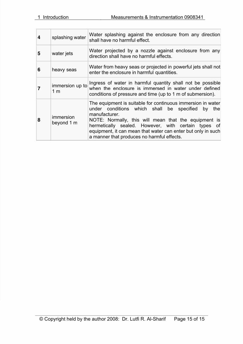
Second digitProtection of the equipment inside the enclosure against harmful ingress of water.
LevelProtectedagainst
Details
0 not protected —
1 dripping water Dripping water (vertically falling drops) shall have no harmfuleffect.
2dripping water when tilted upto 15°
Vertically dripping water shall have no harmful effect whenthe enclosure is tilted at an angle up to 15° from its normalposition.
3 spraying water Water falling as a spray at any angle up to 60° from thevertical shall have no harmful effect.
8/8/2019 1 Introduction to Measurements Systems Rev 7 080215
http://slidepdf.com/reader/full/1-introduction-to-measurements-systems-rev-7-080215 15/15
1 Introduction Measurements & Instrumentation 0908341
© Copyright held by the author 2008: Dr. Lutfi R. Al-Sharif Page 15 of 15
4 splashing water Water splashing against the enclosure from any directionshall have no harmful effect.
5 water jetsWater projected by a nozzle against enclosure from anydirection shall have no harmful effects.
6 heavy seasWater from heavy seas or projected in powerful jets shall notenter the enclosure in harmful quantities.
7immersion up to1 m
Ingress of water in harmful quantity shall not be possiblewhen the enclosure is immersed in water under definedconditions of pressure and time (up to 1 m of submersion).
8immersionbeyond 1 m
The equipment is suitable for continuous immersion in water under conditions which shall be specified by themanufacturer.
NOTE: Normally, this will mean that the equipment ishermetically sealed. However, with certain types of equipment, it can mean that water can enter but only in sucha manner that produces no harmful effects.