1 INTRODUCTION - incosewiki.info · Remember, the MBSE Ontology provided here is not intended to be...
42
Page 1 of 42 Chapter 1.3 - MBSE Concepts ‘Death by Mau-Mau!’ Traditional joke 1 INTRODUCTION This chapter discusses the main systems engineering concepts that were introduced briefly in Chapter 1.1. Understanding the concepts is essential for a number of different reasons, some of which are obvious and some of which are more subtle: - Clearly, by not understanding the basic concepts, actually performing any work in the world of systems engineering is going to be very difficult, to the point of impossible. The only way to succeed whilst not understanding the concepts is through pure chance. This is not a good approach! - In order to address the “three evils” of systems engineering, understanding is crucial. It is one of the basic evils and, as was discussed previously, drives the other two evils. - The basic approach that is advocated in this book for model -based systems engineering is that of: ‘Ontology, Framework and Views’. The concepts needed for MBSE are defined in the so-called MBSE Ontology which forms the cornerstone of any model-based systems engineering exercise. Understanding the concepts is, therefore, essential, and these concepts will be defined using the MBSE Ontology. This Ontology will then be used throughout the rest of this book for all of the examples, approaches and applications of MBSE. 1.1 Provenance of the MBSE Ontology The MBSE Ontology itself is based on a number of best-practice sources that are used throughout the world of systems engineering. The problem with trying to define the MBSE Ontology is that there is no single definitive set of terms for MBSE, therefore a number of sources were considered. The list of information sources is not intended to be exhaustive but is intended to represent a good cross-section of current thought on MBSE. Each of the information sources has its own strengths and weaknesses and, therefore, the approach was to take a consensus of terms wherever possible and where not possible, to give priority to information sources that specialise in a specific area of MBSE. Examples of these information sources include: - ‘ISO 15288 - systems and software engineering life cycle processes’ [ISO15288 2008]. This standard is the most widely-used systems engineering standard in the world. The standard itself is now considered to be quite mature as its first version was published in 2002 and its current version was published in 2008. The standard considers four main areas of processes that ISO suggests should exist in any organisation: technical, project, organisational and agreement. The emphasis of the standard focuses on the technical and project process areas, rather than the organisational and agreement process areas. Indeed, this standard is considered to be particularly weak in depth for both of these areas. Having said that, however, ISO 15288 is an excellent start point for any systems engineering endeavour
-
Upload
trinhthuan -
Category
Documents
-
view
212 -
download
0
Transcript of 1 INTRODUCTION - incosewiki.info · Remember, the MBSE Ontology provided here is not intended to be...

Page 1 of 42
Chapter 1.3 - MBSE Concepts
‘Death by Mau-Mau!’
Traditional joke
1 INTRODUCTION
This chapter discusses the main systems engineering concepts that were introduced briefly in Chapter 1.1.
Understanding the concepts is essential for a number of different reasons, some of which are obvious and some of which are more subtle:
- Clearly, by not understanding the basic concepts, actually performing any work in the world of systems engineering is going to be very difficult, to the point of impossible. The only way to succeed whilst not understanding the concepts is through pure chance. This is not a good approach!
- In order to address the “three evils” of systems engineering, understanding is crucial. It is one of the basic evils and, as was discussed previously, drives the other two evils.
- The basic approach that is advocated in this book for model-based systems engineering is that of: ‘Ontology, Framework and Views’. The concepts needed for MBSE are defined in the so-called MBSE Ontology which forms the cornerstone of any model-based systems engineering exercise.
Understanding the concepts is, therefore, essential, and these concepts will be defined using the MBSE Ontology. This Ontology will then be used throughout the rest of this book for all of the examples, approaches and applications of MBSE.
1.1 Provenance of the MBSE Ontology
The MBSE Ontology itself is based on a number of best-practice sources that are used throughout the world of systems engineering. The problem with trying to define the MBSE Ontology is that there is no single definitive set of terms for MBSE, therefore a number of sources were considered. The list of information sources is not intended to be exhaustive but is intended to represent a good cross-section of current thought on MBSE. Each of the information sources has its own strengths and weaknesses and, therefore, the approach was to take a consensus of terms wherever possible and where not possible, to give priority to information sources that specialise in a specific area of MBSE. Examples of these information sources include:
- ‘ISO 15288 - systems and software engineering life cycle processes’ [ISO15288 2008]. This standard is the most widely-used systems engineering standard in the world. The standard itself is now considered to be quite mature as its first version was published in 2002 and its current version was published in 2008. The standard considers four main areas of processes that ISO suggests should exist in any organisation: technical, project, organisational and agreement. The emphasis of the standard focuses on the technical and project process areas, rather than the organisational and agreement process areas. Indeed, this standard is considered to be particularly weak in depth for both of these areas. Having said that, however, ISO 15288 is an excellent start point for any systems engineering endeavour

Page 2 of 42
and should always be considered when looking for good systems engineering source information.
- ‘INCOSE systems engineering handbook’ [INCOSE 2011]. The International Council on Systems Engineering produces a best-practice guide for systems engineering in the form of a handbook. The handbook itself is based directly on ISO 15288 and, therefore, uses many of the same concepts and terminology. The INCOSE handbook expands greatly on all of the processes in ISO 15288 and also discusses different techniques and approaches to systems engineering. The handbook also has a rich appendix with many examples and case studies of applying systems engineering best practice.
- ‘CMMI - Capability Maturity Model Integrated’ [CMMI 2010]. The CMMI comprises a suite of documents that allow any given set of processes to be assessed in terms of its capability and maturity. The CMMI has an excellent pedigree and is the result of a colossal volume of work. The CMMI is particularly strong when concerned with processes, but rather weaker in other areas, such as architecture.
- ‘DoD - systems engineering guide for systems of systems’ [DoD 2008]. This set of guidelines represents current best practice in the US Department of Defense (sp). This is a particularly valuable source of information as there is a dearth of good, accepted knowledge concerning systems of systems since it is a relatively new area.
- ‘ISO/IEC/IEEE 42010 Systems and software engineering — Architecture description’ [ISO42010 2011]. This is an evolution of ‘IEEE 1471 -
Architectures for software-intensive systems’ [IEEE 2000] and, bearing in mind the history of IEEE 1471, this is now a mature standard. This is an excellent information source for architectures, architecture descriptions and architecture frameworks.
- Various architectural frameworks, including Zachman [Zachman 1987] [Zachman 2008], MODAF [MODAF 2010], DoDAF [DoDAF 2010], NAF [NAF 2007] and TRAK [TRAK 2012]. Architectural frameworks are widely used in today’s industry and provide a good source of information for architectures, architecture descriptions and architectural frameworks. Also, other useful knowledge sources include common notations for frameworks, such as the Unified Profile for DoDAF and MODAF (UPDM) [UPDM 2011] and development processes, such as The Open Group Architectural Framework (TOGAF) [TOGAF 2012]]
- Various competency frameworks, including UKSPEC [UKSPEC 2012], the INCOSE systems engineering competencies framework [INCOSE 2012], SFIA [SFIA 2012], APM [APM 2012] and APMP [2012]. Competency frameworks are widely-used in today’s industry in order to demonstrate the ability of people in an organisation.
- Various modelling notations, including SysML [SysML 2010] [Holt & Perry 2008], UML [UML 2011] [Holt2004], SOAML [SOAML 2009], BPMN [BPMN 2012] etc. There are a number of different modelling notations that may be used for MBSE. This book is concerned with the use of SysML. However, there are some concepts and definitions that are used in other notation that may be of value to the MBSE ontology.

Page 3 of 42
- Various best-practice books. In terms of methodologies and approaches, then there are a number of books that contain valuable knowledge concerning performing MBSE. [Holt 2005] [Holt et al 2011] [Holt & Perry 2010] [Dickerson2009]
- Various papers and other publications such as [Maier 1998] [Lewis 2009] etc.
For each of the main concepts that will be used in the MBSE Ontology, a number of source references will be discussed. The references chosen will vary, depending on the nature of the key concept. For example, CMMI focuses mainly on processes and is therefore an excellent source reference for the Process concept, whereas it does not even mention Systems of Systems and is, therefore, not a good reference for that concept.
1.2 The Systems Engineering Body of Knowledge (SEBoK)
There is an excellent project that is concerned with creating a body of knowledge for systems engineering, known as SEBoK [SEBoK 2012]. This project began in 2009 as part of the larger Body of Knowledge to Advance Systems Engineering (BKCASE) project [BKCASE 2009] with the goal of creating a systems engineering body of knowledge (SEBoK).
There were 70 contributors to the project and one of the goals was to provide a comprehensive set of key references and resources that are relevant to systems engineering and systems engineers.
Released as version 1.0 in 2012, the SEBoK brings together a set of definitions and terms and provides discussion points around them. The goal of SEBoK was not to develop a definite set of terms, but to highlight best practice and to point out differences between them.
It can be plainly seen that there are obvious parallels with this chapter, but with a few notable differences:
- The main focus in this book is specifically model-based systems engineering rather than systems engineering
- The aim of the MBSE Ontology presented in this chapter is, just like SEBoK, to identify any differences of opinion between source references. Unlike SEBoK, however, the MBSE Ontology resolves these discrepancies by making a judgement call and going as far as providing a single definition for each concept, whilst maintaining a mapping back to the source references.
- All of the analysis of source concepts and terms in this book were performed using modelling techniques.
Both the SEBoK and this chapter of the book use many of the same references and, therefore, there is not a graphical representation of SEBoK shown for each of the concepts, as the SEBoK definitions are based directly on source references. Thus, to avoid repetition, the reference to SEBoK is provided once here and not in each section. The SEBoK contains an excellent glossary where the source references for each term can be found.

Page 4 of 42
1.3 Disagreements with the MBSE Ontology
This chapter is intended to define the set of concepts and terms that will be used in this book. They are all based on best-practice definitions but, inevitably, different people in different organisations will disagree with some of the concepts and terms here. The idea of a single Ontology that will be directly and exactly applicable to every organisation can only exist in a utopian world and is simply not realistic in real life. It should be remembered, however, that disagreeing with what is presented here is fine, bearing in mind the following points:
- Disagreeing with terms. It is perfectly natural to disagree with the actual terms that are being used. People working in different organisations, in different industries and even in the same organisation will often use different words to describe the same concept. This is not a problem as long as people are aware of the different terms being used. This is the same as two people speaking two different languages – it does not mean that they cannot communicate, but does mean that there is a requirement for translation between them. The use of an Ontology is an excellent mechanism to achieve this translation.
- Disagreeing with concepts – wrong definition. In some cases there may a concept that is used in the MBSE Ontology which is considered to be completely wrong. Again, this is not necessarily a problem but it does mean that the concept will need to be re-defined. This is achieved by modifying the MBSE Ontology and ensuring that the meaning is still consistent with the rest of the MBSE Ontology.
- Disagreeing with concepts – irrelevant concepts. In some cases there may be concepts on the MBSE Ontology that are considered irrelevant or superfluous to the need of your business. In this case, simply remove them. For example, if your business does not consider Systems of Systems, then there is no value in having that concept on the MBSE Ontology.
- Disagreeing with concepts – missing concepts. In some cases there may be organisation-specific or industry-specific concepts that do not exist on this generic MBSE Ontology. In this case the new concepts need to be added to the MBSE Ontology. Obviously, care must be taken to ensure that the new concepts are consistent with the original MBSE Ontology.
Remember, the MBSE Ontology provided here is not intended to be definitive for every organisation nor industry but, rather, is intended to be a good starting point for creating and tailoring an ontology for your own MBSE activities.
2 THE MBSE ONTOLOGY
This section provides the main definition for the MBSE Ontology along with a discussion of each of the concepts, including the provenance of each.
The basic MBSE Ontology was introduced and described briefly in Chapter 1.1. The same high-level overview is presented again here for reference.

Page 5 of 42
Figure 1 The high-level MBSE Ontology used throughout this book
The diagram here shows the high-level overview of the MBSE Ontology that was introduced in Chapter 1.1. This chapter will take each of the high-level concepts and consider them in more detail. Each concept is grouped with similar and related concepts and presented, described and discussed in its own section. These major groupings are:
- System concepts, that cover the basic concepts associated with System, Systems of Systems, Constituent Systems, etc.
- Need concepts, that cover all concepts associated with System Needs, such as Requirements, Capabilities, Goals, etc.
- Architecture concepts, where the description and structure of Architectures using Architectural Frameworks is discussed.
- Life Cycle concepts, where different Life Cycles and Life Cycle Models are discussed, along with the interactions between Life Cycles.
- Process concepts, where the structure, execution and responsibility of Processes is discussed.
- Competence concepts, where the ability of people associated with Stakeholder Roles is defined,
- Project concepts, where Project and Programme-related concepts are defined.
It is the combination of all these detailed views that will make up the MBSE Ontology in its entirety and which will be presented as a single diagram, showing these major
1..*1
1..*
1
11
1..*1
1..*
1
1..*
1..*
1..*
1
1..*
1
1..*
1
1..*
1..*
1..*
11..*
1..*
1..* 1
1
1
1..*1
1
1..*
1 1..*
1..*
1
1..*
1
1..*
1
1..*
1
*1
1..*1
1..*
1..*
1..*1..*1..*
1
1..*
1
1..*
1
1..*
1
1
1..*
1..*
1
1
1..*
1..*1..* 1..* 1..*
«block»
Scenario
«block»
System
«block»
Architecture
«block»
Life Cycle
«block»
Stakeholder Role
«block»
Stage
«block»
Process Execution Group
«block»
Process
«block»
Activity
«block»
Artefact
«block»
Person
«block»
Constituent System
«block»
System of Systems
«block»
Architectural Framework
«block»
System Element
«block»
Project
«block»
Programme
«block»
Life Cycle Model
«block»
Product
«block»
Service
«block»
Competence
«block»
Organisational Unit
«block»
Organisation
«block»
Context
«block»
Need
«block»
Use Case
1..*1
describes the evolution of
1..*
1
has an interest in
11 describes
1..*1
1..*
1
is executed during
1..*
1..*
is executed during
1..*
1
1..*
1
1..*
1
1..*
1..*
holds
1..*
1
is responsible for
1..*
1..*
produces/consumes
1..* 1
1
1 is structured according to
1..*1
1
1..*
describes the evolution of
1 1..*
shows behaviour of
1..*
1
1..*
1
interfaces with
1..*
1
interacts with
1..*
1
is realised as
*1
interacts with
1..*1
exhibits
1..*
1..*
realises
1..*1..*
runs
1..*
1
1..*
1
shows the order of execution of
1..*
1
produces
1..*
1
interacts with
1
1..*
represents need for
1..*
1
represents need for
1
1..*
represents need for
1..*1..*
puts into context
1..* 1..*
validates

Page 6 of 42
groupings, at the end of this chapter. The MBSE Ontology shown in this chapter is a simplified version of the full MBSE Ontology, which itself is shown in Appendix A.
Each of the major groupings focuses on a number of key concepts that are abstracted from a variety of the source references. These source references are described, discussed and where necessary a model is shown. The concepts are then compared, contrasted and a fully-traceable description is defined that will be used throughout the rest of this book.
2.1 The System concept
One of the most fundamental terms that is used in model-based systems engineering is that of the System. This forms the core definition at the heart of systems engineering and around which the whole MBSE Ontology is based.
System-related concepts as described by the International Standards Organisation (ISO)
‘ISO 15288 – systems and software engineering life cycle processes’ [ISO15288 2008] defines a system as a:
‘combination of interacting elements organised to achieve one or more stated purposes.’
And then goes on to qualify this with an additional note that states:
‘a system may be considered as a product or as the services that it provides’
The standard then continues with a definition of system element as follows:
‘member of a set of elements that constitutes a system’
With a qualifying note that states:
‘… a system element can be hardware, software, data, humans, processes … procedures … facilities, materials and naturally-occurring entities … or any
combination’
In terms of thinking about the System at a conceptual level, ISO defines that a System may be considered as one of two types: a System of Interest or an Enabling System, which are defined as:
‘system of interest (is a) system whose life cycle is under consideration in the context of this International Standard’
‘enabling system (is a) system that supports a system-of-interest during its life cycle stages but does not necessarily contribute to its function during operation.’
This standard is particularly weak when it comes to defining a System of Systems, but does hint at one by stating:
‘for a more complex system-of-interest, a prospective system element may itself need to be considered as a system (that is in turn comprised of system elements)
before a complete set of system elements can be defined with confidence’
Therefore, in summary, the ISO 15288 System-related concepts may be visualised by the following diagram.

Page 7 of 42
Figure 2 Summary of System-related concepts for ISO 15288
The concepts shown in this diagram will be used as a basis for the definitions of the concepts in the MBSE Ontology that will be used for the remainder of this book.
System-related concepts as described by the International Council on Systems Engineering (INCOSE).
The ‘INCOSE systems engineering handbook’ [INCOSE2011] is based directly on ISO 15288 but expands on all of the points made in it, including definitions, processes and life cycles. As a result of this, the definitions for: System, Enabling System, System of Interest and System Element are exactly the same as those definitions provided in ISO 15288. INCOSE does not explicitly define the terms Products or Services, but do allude to the fact that systems engineering is intended to ‘establish agreement for the creation of products and services’ which may be interpreted as a similar definition to that provided in ISO 15288.
INCOSE, however, does enter into more detail when defining a System of Systems, using the definition:
‘systems of systems (SoS) are defined as an interoperating collection of component systems that produce results unachievable by the individual systems alone’
This provides a difference from the loose definition provided in ISO 15288 and introduces the idea that a System of Systems has its own ‘results’ - this is not explicit in the ISO 15288 definition.
Therefore, in summary, the INCOSE System-related concepts may be visualised by the following diagram.
1..*
1
1..*1
1..* 1
*
1
1..*1
«block»
System
«block»
System Element
«block»
Material «block»
System-of-Interest
«block»
Enabling System
«block»
Person
«block»
Process
«block»
Hardware
«block»
Software
«block»
Product
«block»
Service
1..*
1
is realised by
1..*1
is realised by
1..* 1
*
1
provides
1..*1
interacts with
{incomplete}

Page 8 of 42
Figure 3 Summary of the System-related concepts for INCOSE
The concepts shown in this diagram will be used as a basis for the definitions of the concepts in the MBSE Ontology that will be used for the remainder of this book.
System-related concepts as described by the US Department of Defense
The US Department of Defense (DoD) have issued a set of systems engineering guidelines that are aimed specifically at Systems of Systems [DoD2008]. The guidelines define a System as:
‘a functionally, physically and/or behaviourally related group of regularly interacting or interdependent elements; that group of elements forming a unified whole’
This definition, whilst using different terms, is very similar to that used in both ISO 15288 and the INCOSE handbook. The emphasis of these guidelines is on the concept of Systems of Systems, therefore the definition used should be particularly interesting.
‘An SoS is defined as a set or arrangement of systems that results when independent and useful systems are integrated into a larger system that delivers
unique capabilities.’
The relationship between the concepts of System and System of Systems is further elaborated on by the statement:
‘… although an SoS is a system, not all systems are SoS’
This definition really states that there is a generalisation relationship between System and System of Systems.
The guidelines then continue by identifying four main types of System of Systems, as defined by Maier [Maier1998], which are:
- Virtual - ‘Virtual SoS lack a central management authority and a centrally agreed upon purpose for the system-of-systems. Large-scale behavior emerges - and may be desirable - but this type of SoS must rely upon relatively invisible mechanisms to maintain it.’
- Collaborative - ‘In collaborative SoS the component systems interact more or less voluntarily to fulfill agreed upon central purposes. The Internet is a collaborative system. The Internet Engineering Task Force works out standards but has no power to enforce them. The central players collectively
1..* 11..* 1
1..*1
1..*1
*
11..*
1
1..*1
«block»
System Element
«block»
Component System
«block»
System of Systems
«block»
System-of-Interest
«block»
Enabling System
«block»
System
«block»
Product
«block»
Service
1..* 11..* 1
1..*1
interacts with
1..*1
interacts with
*
1
provides
1..*
1
is realised by
1..*1
is realised by

Page 9 of 42
decide how to provide or deny service, thereby providing some means of enforcing and maintaining standards.’
- Acknowledged - ‘Acknowledged SoS have recognized objectives, a designated manager, and resources for the SoS; however, the constituent systems retain their independent ownership, objectives, funding, and development and sustainment approaches. Changes in the systems are based on collaboration between the SoS and the system.’
- Directed - ‘Directed SoS are those in which the integrated system-of-systems is built and managed to fulfill specific purposes. It is centrally managed during long-term operation to continue to fulfill those purposes as well as any new ones the system owners might wish to address. The component systems maintain an ability to operate independently, but their normal operational mode is subordinated to the central managed purpose.’
Therefore, in summary, the US DoD System-related concepts may be visualised by the following diagram.
Figure 4 Summary of System-related concepts for the DoD
The concepts shown in this diagram will be used as a basis for the definitions of the concepts in the MBSE Ontology that will be used for the remainder of this book.
The MBSE Ontology definition for System-related concepts
The concepts and definitions that will be used in this book are shown in the following diagram.
1..* 11..* 1
1..*
1
1..*
1«block»
Element
«block»
Individual System
«block»
System of Systems
«block»
System
«block»
Virtual
«block»
Acknowledged
«block»
Collaborative
«block»
Directed
1..* 11..* 1
1..*
1
interacts with
1..*
1
interacts with

Page 10 of 42
Figure 5 MBSE Ontology focussed on System concepts
The diagram here shows the MBSE Ontology for the main concepts that are related to the System. The structure of the diagram is very similar to those of ISO 15288 and the DoD guide. The main structure of the ‘System’ is taken from ISO 15288, whereas the ‘System of Systems’ structure is taken mainly from the DoD guide.
These concepts are defined as follows:
- ‘System’ – set of interacting elements organised to satisfy one or more ‘System Context’. Where the ‘System’ is a ‘System of Systems’, then its elements will be one or more ‘Constituent System’, and where the ‘System’ is a ‘Constituent System’ then its elements are one or more ‘System Element’. A ‘System’ can interact with one or more other ‘System’.
- ‘Constituent System’ – a special type of ‘System’ whose elements are one or more ‘System Element’.
- ‘System of Systems’ – a special type of ‘System’ whose elements are one or more ‘Constituent System’ and which delivers unique functionality not deliverable by any single ‘Constituent System’.
- ‘System of Interest’ – a special type of ‘System’ that describes the system being developed, enhanced, maintained or investigated.
- ‘Enabling System’ – a special type of ‘System’ that interacts with the ‘System of Interest’ yet sits outside its boundary.
- ‘System Element’ – a basic part of a ‘Constituent System’.
1..* 11..* 1
*
11..*1
1..* 1
11..*
1..*
1
«block»
System
«block»
Constituent System
«block»
System of Systems
«block»
Acknowledged
«block»
Collaborative
«block»
Directed
«block»
Virtual
«block»
System Element
«block»
Product
«block»
Service
«block»
System Context
«block»
System of Interest
«block»
Enabling System
1..* 11..* 1
*
1
interacts with
1..*1 is realised as1..* 1
represents the need for
11..*
interacts with
1..*
1
interacts with

Page 11 of 42
- ‘Product’ – something that realises a ‘System’. Typical products may include, but are not limited to: software, hardware, Processes, data, humans, facilities, etc.
- ‘Service’ – an intangible ‘Product,’ that realises a ‘System’. A ‘Service’ is itself is realised by one or more ‘Process’ (See also: ‘Process’).
- ‘Virtual’ – a special type of ‘System of Systems’ that lacks central management and resources, and no consensus of purpose.
- ‘Collaborative’– a special type of ‘System of Systems’ that lacks central management and resources, but has consensus of purpose.
- ‘Acknowledged’– a special type of ‘System of Systems’ that has designated management and resources, and a consensus of purpose. Each ‘Constituent System’ retains its own management and operation.
- ‘Directed’– a special type of ‘System of Systems’ that has designated management and resources, and a consensus of purpose. Each ‘Constituent System’ retains its own operation but not management.
This subset of the MBSE Ontology has direct relationships to the ‘Need’, ‘Life Cycle’ and ‘Process’ subsets that are described in this chapter.
2.2 The Need concept The concept of a Need that is used here is a generalisation of a number of terms, including the terms Requirement, Capability and Goal. This section will, therefore, look at several definitions of these terms and then define exactly what is meant by them for the purposes of this book.
Need-related concepts as described by the Oxford English Dictionary
The basic definition of a Requirement in the Oxford English Dictionary is:
‘(noun) a thing that is needed or wanted’ [OED]
This definition, albeit a very high-level one, is very interesting for two main reasons: - A Requirement is basically defined as a ‘thing’ – not the most unambiguous of
definitions. - This ‘thing’ is either ‘needed’ or ‘wanted’. This is particularly interesting as there is
often a big difference between what a Stakeholder Role wants and what they actually need. Indeed, part of any Requirements analysis activity should concern itself with the difference between these two terms.
This is a somewhat ambiguous definition of the term.
Need-related concepts as described by the International Council on Systems Engineering (INCOSE).
The next definition that will be considered is taken from the world of systems engineering. The whole area of systems engineering advocates that requirements must be understood so much so that the areas of Requirements engineering and systems engineering are often confused. The next definition, therefore, is taken from the International Council on Systems Engineering (INCOSE) handbook [INCOSE2011].
‘A statement that identifies a system, product or process characteristic or constraint, which is unambiguous, clear, unique, consistent, stand-alone (not grouped), and verifiable, and is
deemed necessary for stakeholder acceptability.’

Page 12 of 42
This definition is more complex that the previous one, but also shares some characteristics with it. Consider the following:
- For the first time, this definition states explicitly that a Requirement takes the form of a ‘statement’.
- This definition then states that a Requirement is a ‘system, product or process characteristic or constraint’. This is, essentially, putting a better definition to the term ‘thing’ that was used in the first definition.
- The definition then goes on to qualify this statement, by stating that it must be ‘unambiguous, clear, unique, consistent, stand-alone (not grouped), and verifiable’. This set of basic characteristics will be discussed throughout this book but, suffice to say, there exists a set of desirable characteristics for any Requirement.
- The final part of the INCOSE definition states that the Requirement is ‘deemed necessary for stakeholder acceptability’. This is very much in the ‘needed’ rather than ‘wanted’ camp when compared to the OED definition.
In conclusion, therefore, a fuller definition of the term that adds more detail when compared with the OED definition.
Need-related concepts as described by the modelling community
The next definition of the term Requirement is taken from the world of modelling. This is an important definition as modelling is core to the whole approach taken in this book. This definition is taken from the Unified Modelling Language definition:
‘a desired feature, property or behaviour of a system’ [Rumbaugh 2004]
This definition is certainly simpler that the INCOSE one and has a number of noteworthy aspects.
- The term ‘desired’ is used here, which really sits somewhere between ‘wanted’ and ‘needed’.
- The term Requirement is defined in the Context of being a property of a System, rather than the Context of the Stakeholder.
In conclusion, therefore, another simple definition and, again, one that is very similar to both the INCOSE and OED definitions.
In the seminal book ‘Model-based requirements engineering’ [Holt et al 2011] the idea of a Need is taken further by considering the Context and also how it will be validated. The key terms are shown in the diagram below.

Page 13 of 42
Figure 6 Summary Need-related concepts as described in 'Model-based requirements engineering'
The concepts here consider the ‘Requirement’ as an abstract concept that has a ‘Requirement Description’ but that also has its ‘Context’ defined in terms or one or more ‘Use Case’. Each ‘Use Case’ may then be validated by one or more ‘Scenario’. This is the first definition where the concepts of a basic need (shown here as ‘Requirement’) are taken further and related to other established modelling concepts (the ‘Use Case’ and the ‘Scenario’). This is further extended by considering traceability back to one or more ‘Source Element’ and the concept of a ‘Rule’ that may be defined in order to constrain one or more ‘Requirement’.
Need-related concepts as described by the International Standards Organisation (ISO)
The next definition that will be considered is taken from the generic quality-based standard - ISO 9001 [ISO9001 2008] which defines a Requirement as:
‘need or expectation that is stated, generally implied or obligatory’
Again, this may appear to be a simple definition, but there are some interesting points to be made here.
- For the first time, the term ‘expectation’ is used here as an alternate to ‘need’. The main difference between these two terms is that one is more specific than the other. A need must to be stated, whereas an expectation may be viewed as more assumed than stated.
- Following directly on from the previous point, this definition provides three qualifiers on the term ‘requirement’. It states that a Requirement may be ‘stated’ explicitly, ‘generally implied’ implicitly or ‘obligatory’ in that it is mandatory.
In conclusion, therefore, this definition has similarities with the previous definitions, but adds more detail with the nature of the Requirement.
The MBSE Ontology definition for Need-related concepts
Based on these information sources, the following section of the MBSE Ontology was defined.
1 1..*
1..*
1..*
1
1
1..*
*
1..*
1..*
Context
Use Case
Scenario
Semi-formal Scenario Formal Scenario
System Context
Stakeholder ContextSource Element
Business Requirement
Functional Requirement
Requirement Description
Rule
Non-functional Requirement
Requirement{Abstract}
1 1..*
describes the context of
1..*
1..*
is elicited from
1
1
describes
1..*
*
constrains
1..*
1..*
validates
{incomplete}

Page 14 of 42
Figure 7 - MBSE Ontology focussed on Need concepts
The diagram here shows the MBSE ontology for the main concepts that are related to need concepts. These are defined as follows:
- ‘Need’ – a generic abstract concept that, when put into a ‘Context’, represents something that is necessary or desirable for the subject of the Context.
- ‘Need Description’ – a tangible description of an abstract ‘Need’ that is defined according to a pre-defined set of attributes.
- ‘Goal’– a special type of ‘Need’ whose ‘Context’ will typically represent one or more ‘Organisational Unit’ (as an ‘Organisational Context’). Each ‘Goal’ will be met by one or more ‘Capability’.
- ‘Capability’ – a special type of ‘Need’ whose ‘Context’ will typically represent one or more ‘Project’ (as a ‘Project Context’) or one or more ‘Organisational Unit’ (as an ‘Organisational Context’). A ‘Capability’ will meet one or more ‘Goal’ and will represent the ability of an ‘Organisation’ or ‘Organisational Unit’.
- ‘Requirement’- a property of a System that is either needed or wanted by a
‘Stakeholder Role’ or other Context-defining element. Also, one or more ‘Requirement’ is needed to deliver each ‘Capability’.
- ‘Source Element’ –the ultimate origin of a ‘Need’ that is elicited into one or more ‘Need Description’. A ‘Source Element’ can be almost anything that inspires, effects or drives a ‘Need’, such as: a Standard, a System, Project documentation, a phone call, an email, a letter, a book etc.
- ‘Rule’ – is a construct that constrains the attributes of a ‘Need Description’. A ‘Rule’ may take several forms, such as: equations, heuristics, reserved word lists, grammar restrictions, etc.
- ‘Use Case’ – a ‘Need’ that is considered in a specific ‘Context’ and that is validated by one or more ‘Scenario’
- ‘Context’ – a specific point of view based on, for example: Stakeholder Roles, System hierarchy level, Life Cycle Stage, etc.
1..* 1..*
1..*
*
1
1..*1
1..*
1..*1..*1..*
1..*
1
1 **
«block»
Rule
«block»
Source Element
«block»
Capability
«block»
Goal
«block»
Requirement
«block»
Scenario
«block»
Need Description
«block»
Formal Scenario
«block»
Semi-formal Scenario
«block»
Organisational Context
«block»
Project Context
«block»
Stakeholder Context
«block»
System Context
«block»
Context
«block»
Use Case
«block»
Need
1..* 1..*
is elicited from
1..*
* constrains
1
1..*
meets
1
1..*
is needed to deliver
1..*1..*
puts into context
1..*
1..*
validates
1
1
describes
**
is derived from
{incomplete}

Page 15 of 42
- ‘Scenario’ – an ordered set of interactions between or more ‘Stakeholder Role’, ‘System’ or ‘System Element’ that represents a specific chain of events with a specific outcome. One or more ‘Scenario’ validates each ‘Use Case’
- ‘Formal Scenario’ – a ‘Scenario’ that is mathematically-provable using, for example, formal methods.
- ‘Semi-formal Scenario’- a ‘Scenario’ that is demonstrable using, for example, visual notations such as SysML, tables, text, etc.
The ‘Need’ subset of the MBSE Ontology has relationships with the ‘Project’ and ‘System’ subsets.
2.3 The Architecture concept
The concept of an architecture is fundamental to any systems engineering undertaking. There is much confusion, however, due to the plethora of very similar terms involving the word architecture. The use of architecture has also changed significantly over the years as the definitions that apply to the world of software engineering have a significantly-simpler scope than the world of systems engineering.
Architecture-related concepts as described by the International Standards Organisation (ISO).
There are two main ISO standards that will be considered for the source knowledge for defining architecture, which are:
- ISO 15288 – Systems and software engineering -- System life cycle processes. This standard is used many times in this book, but has surprisingly-little information concerning architecture. [ISO15288 2008]
- ISO 42010 – Systems and software engineering — Architecture description. This standard is more recent that ISO 15288 and is concerned solely with architectures. The terminology provided in this standard, therefore, is very well defined and has far more detail than in ISO 15288. [ISO 42010 2011]
In ISO 15288, the definition of an architecture is given as:
‘fundamental organisation of a system embodied in its components, their relationships to each other, and to the environment, and the principles guiding its
design and evolution.’
ISO/IEC 42010 defines a number of terms: architecting: process of conceiving, defining, expressing, documenting,
communicating, certifying proper implementation of, maintaining and improving an architecture throughout a system’s life cycle
architecture: fundamental concepts or properties of a system in its environment embodied in its elements, relationships, and in the principles of its design and evolution
architecture description (abbreviation 'AD'): work product used to express an architecture
architecture description language (abbreviation 'ADL'): any form of expression for use in architecture descriptions

Page 16 of 42
architecture framework: conventions, principles and practices for the description of architectures established within a specific domain of application and/or community of stakeholders
architecture viewpoint: work product establishing the conventions for the construction, interpretation and use of architecture views to frame specific system concerns
architecture view: work product expressing the architecture of a system from the perspective of specific system concerns
concern: interest in a system relevant to one or more of its stakeholders. A concern pertains to any influence on a system in its environment, including developmental, technological, business, operational, organizational, political, economic, legal, regulatory, ecological and social influences.
environment: context determining the setting and circumstances of all influences upon a system. The environment of a system includes developmental, technological, business, operational, organizational, political, economic, legal, regulatory, ecological and social influences.
stakeholder : individual, team, organization, or classes thereof, having an interest in a system
The fundamental definition of the term ‘architecture’ is almost identical between the two standards, but ISO 42010 provides far more definitions that ISO 15288 and will used as the main knowledge source for this section.
Figure 8 Summary Architecture-related concepts for ISO 42010
The diagram here shows a summary of the architecture-related terms for ISO 42010. As the definition of ‘architecture’ in ISO 15288 is almost identical, then this diagram can be seen to represent both standards accurately.
1 1..*
1
1..*
1..*
1
1..*
1
1..*
1
1..*
1..*
11..*
11
1..*
1
1..*
1
1..*
1
1
1..* 1..* 1 1..*1 1..*1
1..*
1
1..*
1
1
*
«block»
Principle
«block»
Architecture
«block»
Concept
«block»
Element
«block»
Design Principle
«block»
Evolution Principle
«block»
System
«block»
Stakeholder
«block»
Concern
«block»
Architecture Framework
«block»
Architecture Description
«block»
Architecture Viewpoint
«block»
Architecture View
«block»
Environment
1 1..*
applies to a specific group of
1
1..*
has an interest in
1..*
1
addesses
1..*
1
1..*
1
1..*
1..*
is produced according to
11..*
governs
11
exhibits
1..*
1
1..*
1
1..*
1
1
1..*
expresses
1..* 1
defines established views of
1..*1
identifies
1..*1
identifies
1..*
1
identifies
1..*
1
identifies
1
*
is situated in

Page 17 of 42
Architecture-related concepts as described by the International Council on Systems Engineering (INCOSE).
The INCOSE handbook does not provide an explicit definition of what an architecture is, yet does refer to several different types of architecture, such as: system architecture, logical architecture, functional architecture, enterprise architecture,
‘there may be several required operational views of the system driven by architectural frameworks’
As has been mentioned previously, the INCOSE handbook is, in many ways, an expansion of ISO 15288 which itself is weak where architectures are concerned.
Architecture-related concepts as described by the Architecture Framework community
When architectures are used for a specific industry, or a specific stakeholder group, it is quite common for an Architecture Framework to be defined. An Architecture Framework is not, in itself, an Architecture, but defines a set of Views that are required to describe an Architecture.
A number of Architecture Frameworks will be considered at a very high level. For a more in-depth description see [Holt&Perry2010].
The Zachman framework
The Zachman Framework is a framework for Enterprise Architecture. The Zachman Framework is one of the oldest and most mature frameworks and is certainly one of the most widely-used in industry today [Zachman 1987] [Zachman 2008].
Zachman derived the framework from the world of classical (building) architecture and, hence, the names of the views and the perspectives relate to the terminology of architecture.
The diagram below shows a high-level view of the Zachman framework.
Figure 9 - Summary of the Architecture-related concepts for Zachman
6
1
1..6
1
1..* 1..*
1 6
1
1
1 1
«block»
Zachman Framework
«block»
Entity
«block»
Matrix
«block»
Communication
Interrogative
«block»
Reification
Transformation
«block»
Descriptive Representation
«block»
Architecture
«block»
What
«block»
How
«block»
When
«block»
Who
«block»
Where
«block»
Why
«block»
Definition
«block»
Representation
«block»
Specification
«block»
Configuration
«block»
Instantiation
«block»
Identification
6
1
1..6
1
1..* 1..*
describes
1 6describes
1
1
is depicted as
1 1
is the basis for

Page 18 of 42
The framework itself takes the form of a simple ‘Matrix’ comprising rows and columns with intersecting cells that describe aspects of an entity. Usually there are 36 cells as the matrix usually has six rows and always has six columns.
Each row represents between one and six ‘Communication Interrogative’, each of which asks a basic question regarding the ‘Entity’ that is under consideration. These questions take the basic form of: ‘What’, ‘How’, ‘When’, Who’, ‘Where’ and ‘Why’. Each column represents a ‘Reification Transformation’ that covers the broad transformation of information from a vague abstraction into a solid instantiation. These are:
- ‘Identification’ which is often represented on the matrix as scope contexts and that is mainly applicable to strategists as theorists
- ‘Definition’ which is often represented on the matrix as business contexts and that is mainly applicable to executive leaders as owners
- ‘Representation’ which is often represented on the matrix as system logics and that is mainly applicable to architects as designers
- ‘Specification’ which is often represented on the matrix as technology physics and that is mainly applicable to engineers as builders
- ‘Configuration’ which is often represented on the matrix as component assemblies and that is mainly applicable to technicians as implementers
- ‘Instantiation’ which is often represented on the matrix as operations and instance classes and that is mainly applicable to workers as participants
The Zachman has been used as a major reference for most architectural frameworks, including the ones described in this section.
Defence-based Architecture Frameworks.
The defence industry has a number of architectural frameworks that originate in and are used by particular countries. These include:
- MODAF – Ministry of Defence Architecture Framework [MODAF 2010] which originated and is used in the UK.
- DoDAF – Department of Defense Architecture Framework [DoDAF 2007] which originated and is used in the USA.
- NAF – NATO Architecture Framework [NAF 2007], which is used in NATO countries.
- DNDAF – DND/ CF Architecture Framework [DNDAF 2012], which originated and is used in Canada.
The list goes on with many countries having their own specific framework, but most of them are closely related and, therefore, have very similar constructs and concepts. For the sake of brevity and the reader’s sanity, a single one will be considered as a knowledge source – for a more in-depth comparison see [ISO 2012]. In addition, to learn more about common notation for defence frameworks, see [UPDM 2012].
The UK Ministry of Defence Architectural Framework (MODAF) defines an architectural framework as:
‘An Architectural Framework (AF) is a specification of how to organise and present architectural models. … an AF defines a standard set of model categories (called
‘Views’) which each have a specific purpose. These views are often categorised by

Page 19 of 42
the domain they cover – e.g. operational / business, technical, etc. – which are known in MODAF as Viewpoints’
In terms of the application of MODAF, its scope includes:
‘MODAF provides a rigorous method for understanding, analysing, and specifying: Capabilities, Systems, Systems of Systems (SoS), Organisational Structures and
Business Processes.’
The MODAF specification identifies seven viewpoints that are required to make up the full architectural framework. Note that this is a different definition of the term ‘Viewpoint’ from the one used in ISO 42010.
Figure 10 Summary of the MODAF architecture-related concepts
The MODAF is made up of seven ‘Viewpoint’ each of which is made up of one or more ‘View’. These viewpoints are simply collections of views and serve to group views that are used for similar purposes. The viewpoints are: ‘All Views’ that describe information that applies to all viewpoints, the ‘Strategic’ viewpoint that describes capabilities, the ‘Operational’ viewpoint that describes concepts, the ‘System’ viewpoint that describes the actual systems, the ‘Service-oriented’ viewpoint that describes the actual services, the ‘Acquisition’ viewpoint that describes acquisition programme views and the ‘Technical’ viewpoint that identifies relevant standards.
The various defence-based frameworks are related to each other and so, unsurprisingly, have a number of similarities. In order to illustrate these similarities the following table provides a high-level mapping between the terms that are used in several frameworks.
MODAF DoDAF NAF
Viewpoint View View
View Product Subview
All Viewpoint All View NATO All View
Acquisition Viewpoint - NATO Programme View
7
1
1..*
1
1..*
1
1..* 1 «block»
MODAF
«block»
Viewpoint
«block»
View
«block»
Aspect
«block»
Architectural Model
«block»
System
«block»
System of Systems
«block»
Organisational Structure
«block»
Business Process
7
1
1..*
1
1..*
1
1..* 1
provides a specification of how to represent
{incomplete}
Page 20 of 42
Strategic Viewpoint - NATO Capability View
Operational Viewpoint Operational View NATO Operational View
Systems Viewpoint Systems and Services View NATO Systems View
Service-oriented Viewpoint Systems and Services View NATO Service-oriented View
Technical Viewpoint Technical Standards View NATO Technical view
Figure 11 Comparison of terms in defence-based architectural frameworks
The table shown here is not intended to be an exhaustive comparison but is intended to make the point that there are many similarities between the various defence-based architectural frameworks. For a full discussion on the similarities and differences between these frameworks, including models of the different structures, see [Holt&Perry2010].
Non-defence Architecture Frameworks
Alongside the defence-based architectural frameworks, there are a number of non-defence architecture frameworks (note the difference in terms here, where the term ‘architectural framework’ was used in defence, the term ‘architecture framework’ is used here; both mean the same thing).
Perhaps the most widely-known is The Open Group Architecture Framework (TOGAF) [TOGAF 2012] which is not actually an architecture framework but, rather, a set of phases and associated processes in the form of an architecture development method (ADM) that will enable an enterprise architecture to be created for an organisation.
TOGAF does not define any particular views (although it does hint strongly at some) but focuses on how to manage the development and delivery of the architecture. This is an important point as the TOGAF is effectively a management-based approach and, hence, focuses largely on management and planning, rather than the actual development of the architecture and its views.
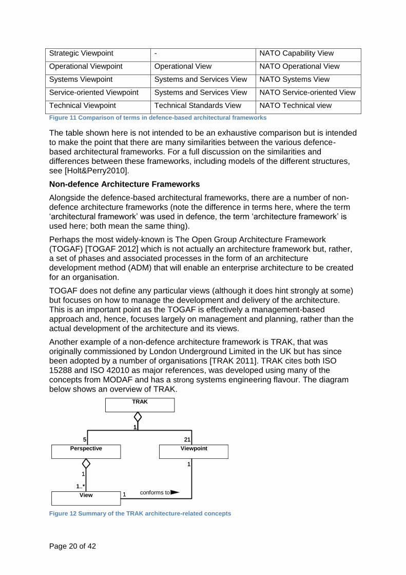
Another example of a non-defence architecture framework is TRAK, that was originally commissioned by London Underground Limited in the UK but has since been adopted by a number of organisations [TRAK 2011]. TRAK cites both ISO 15288 and ISO 42010 as major references, was developed using many of the concepts from MODAF and has a strong systems engineering flavour. The diagram below shows an overview of TRAK.
Figure 12 Summary of the TRAK architecture-related concepts
5
1
1
1
1..*
1
21
1
TRAK
ViewpointPerspective
View
5
1
1
1
conforms to1..*
1
21
1

Page 21 of 42
The diagram here shows that ‘TRAK’ is made up of five ‘Perspective’ that groups one or more elated ‘View’ and 21 ‘Viewpoint’. Each ‘View’ is defined according to one ‘Viewpoint’.
The MBSE Ontology definition for Architecture
Based on these knowledge sources, the following Ontology was defined.
Figure 13 – MBSE Ontology for Architectures and Architectural Frameworks
The concepts shown on Figure 13 are defined as follows:
'Architectural Framework' - a defined set of one or more ‘Viewpoint' and an ‘Ontology'. The ‘Architectural Framework’ is used to structure an ‘Architecture’ from the point of view of a specific industry, Stakeholder Role set, or Organisation. The ‘Architectural Framework’ is defined so that it meets the Needs defined by one or more ‘Architectural Framework Concern’. An ‘Architectural Framework’ is created so that it complies with zero or more ‘Standard’.
'Architectural Framework Concern' - defines a Need that an ‘Architectural Framework’ has to address.
'Ontology' - an element of an ‘Architectural Framework’ that defines all the concepts and terms (one or more ‘Ontology Element’) that relate to any ‘Architecture’ structured according to the ‘Architectural Framework’.
'Ontology Element' - the concepts that make up an ‘Ontology’. Each ‘Ontology Element’ can be related to each other and is used in the definition of each ‘Viewpoint’ (through the corresponding ‘Viewpoint Element’ that makes up a ‘Viewpoint’). The provenance for each ‘Ontology Element’ is provided by one or more ‘Standard’.
'Viewpoint '- a definition of the structure and content of a ‘View’. The content and structure of a ‘Viewpoint’ uses the concepts and terms from the ‘Ontology’ via one or more ‘Viewpoint Element’ that make up the ‘Viewpoint’. Each ‘Viewpoint’ is defined so that it meets the needs defined by one or more ‘Viewpoint Concern’.
'Viewpoint Concern' - defines a Need that a ‘Viewpoint’ has to address.
‘Viewpoint Element’ - the elements that make up a ‘Viewpoint’. Each ‘Viewpoint Element’ must correspond to an ‘Ontology Element’ from the ‘Ontology’ that is part of the ‘Architectural Framework’.
1..*
1..*
1
1..*
*
1
1..*
1
1 1..*
1..*
1
1..*
1
1 1..*
1..*
1
1
111
1..*
1
1..*11..*
1
1..*
1
1..*1
1..*1
1..*
1
1..*
1
1
1
1..*
1
1
1..*
1
1..* «block»
Architectural Framework
Concern
«block»
Viewpoint Concern
«block»
View
«block»
View Element
«block»
Architecture
«block»
Perspective
«block»
Viewpoint
«block»
Viewpoint Element
«block»
System
«block»
Architectural Framework
«block»
Ontology Element
«block»
Ontology
«block»
Standard
«block»
Rule
1..*
1..*
is derived from
1
1..*represents need for
*
1
complies with
1..*
1
1 1..*conforms to
1..*
1
1..*
1
collects together
1 1..*
visualises
1..*
1
collects together
1
1 describes11
describes structure of
1..*
1
1..*1
corresponds to1..*
1
related to
1..*
1
1..*1 uses elements from
1..*1
is related to
1..*
1
1..*
1
is related to
1
1
1..*
1
provides provenance for
1
1..*
constrains
1
1..*
represents need for

Page 22 of 42
‘Architecture’ - a description of a ‘System’, made up of one or more ‘View’. One or more related ‘View’ can be collected together into a ‘Perspective’.
‘View’ - the visualisation of part of the ‘Architecture’ of a ‘System’, that conforms to the structure and content defined in a ‘Viewpoint’. A ‘View’ is made up of one or more ‘View Element’.
‘View Element’ - the elements that make up a ‘View’. Each ‘View Element’ visualises a ‘Viewpoint Element’ that makes up the ‘Viewpoint’ to which the ‘View’, on which the ‘View Element’ appears, conforms.
‘Perspective’ - a collection of one or more ‘View’ (and hence also one or more defining ‘Viewpoint’) that are related by their purpose. That is, one or more ‘View’ which address the same architectural needs, rather than being related in some other way, such as by mode of visualisation, for example.
‘Rule’ - a construct that constrains the ‘Architectural Framework’ (and hence the resulting ‘Architecture’) in some way, for example by defining one or more ‘Viewpoint’ that are required as a minimum.
‘System’ - set of interacting elements organised to satisfy one or more Needs. The artefact being engineered that the ‘Architecture’ describes.
It is important to note here that an Architecture is simply considered to be a description of a System, represented by a number of Views that are created according to a number of predefined Viewpoints from a given Architectural Framework.
There are a number of terms from the Ontology in Figure 13 that perhaps need some clarification, namely Architectural Framework, Architecture, Viewpoint and View. The following clarification should help:
An Architectural Framework is made up of a number of Viewpoints that define the information that can be presented.
An Architecture is based on an Architectural Framework. It is made up of Views, with each View a realisation of a Viewpoint.
Viewpoints define the information that can be presented; it is a definition of what can be produced when an Architecture is based on an Architectural Framework.
A View is an artefact, produced as part of an Architecture. It describes an aspect of that Architecture. If the Architecture is created using an Architectural Framework, then every View will conform to a Viewpoint in the Architectural Framework.
Not all Architectural Frameworks make this distinction. For example, MODAF makes no such distinction. It defines a number of Views but does not differentiate between the definition and realisation in terms of the language and terms used. Even more confusingly MODAF does use the term “viewpoint”, but in MODAF a “viewpoint” is the same as Perspective in Figure 13, simply a collection of related Views.
The ‘Architecture’ subset has relationships with the ‘System’ and the ‘Need’ subsets.
2.4 The ‘Life Cycle’ concept
The concept of a Life Cycle may seem to be quite a simple one. However, complexity creeps in when the following are considered:
- The application of the Life Cycle. For example, does the Life Cycle apply to development, acquisition, a Product, a Project, an Organisation, etc.?
- The relationships and interactions between different Life Cycles. For example, how do acquisition and development Life Cycles interact with one another?

Page 23 of 42
Life Cycles also feature heavily in the world of Processes, so some additional knowledge sources start to become relevant here, such as CMMI.
Life Cycle-related concepts as described by the International Standards Organisation (ISO)
The concept of a life cycle is fundamental to ISO 15288 and, indeed, features in the title of the standard [ISO15288 2008]. ISO 15288 describes a life cycle as the:
‘evolution of a system, product, service, project or other human-made entity from conception through retirement’
The standard then continues to describe a stage as:
‘period within the life cycle of an entity that relates to the state of its description or realization’
The standard also describes a number of typical stages that are not covered here but will be discussed in more detail in Chapter 3.2.
Figure 14 Summary of the Life Cycle-related concepts for ISO 15288
The diagram here shows that a ‘Life Cycle’ is made up of one or more ‘Stage’ and that it describes the evolution of an ‘Entity’ which can have many types.
Again, the diagram here appears to be quite simple with a straightforward structure, but more complexities will be discussed in Chapter 3.2 where life cycles and processes will be considered in greater detail.
Life Cycle-related concepts as described by the Capability Maturity Model Integration (CMMI)
The Capability Maturity Model Integration (CMMI) is mainly concerned with processes but also covers life cycles in some detail [CMMI2010]. CMMI uses the term ‘life cycle model’ which is defined as:
‘A partitioning of the life of a product or project into phases’
CMMI also uses the term ‘product life cycle’ which is defined as:
‘The period of time, consisting of phases, which begins when a product is conceived and ends when the product is no longer available for use. Since an organization may be producing multiple products for multiple customers, one description of a product
lifecycle may not be adequate. Therefore, the organization may define a set of
1..*
1
1 1 «block»
Life Cycle
«block»
Stage
«block»
Entity
«block»
System
«block»
Service
«block»
Product
«block»
Project
1..*
1
1 1describes the evolution of

Page 24 of 42
approved product lifecycle models. These models are typically found in published literature and are likely to be tailored for use in an organization. A product lifecycle
could consist of the following phases: (1) concept/vision, (2) feasibility, (3) design/development, (4) production, and (5) phase out.’
These concepts are summarised in the diagram below.
Figure 15 Summary of Life Cycle-related concepts for CMMI
The diagram here shows that a ‘Life Cycle Model’ is made up of one or more ‘Phase’ and partitions the life of one or more ‘Project’ or ‘Product’. Note that there is an ambiguity in the terms that are used in CMMI between: ‘Product Life Cycle’, ‘Life Cycle Model’ and ‘Product Life Cycle Model’, which all seem to be used interchangeably.
The MBSE Ontology definition
Based on these knowledge sources, the following MBSE Ontology was defined.
1..*
1
1..*
1
1..* 1
«block»
Project
«block»
Product
«block»
Life Cycle Model
«block»
Phase
1..*
1
1..*
1
partitions the life of
1..* 1
partitions the life of

Page 25 of 42
Figure 16 MBSE Ontology focussed on Life Cycle concepts
The diagram here shows the MBSE Ontology for the main concepts that are related to life cycles. These are defined as follows:
- ‘Life Cycle’ – a set of one or more ‘Stage’ that can be used to describe the evolution of ‘System’, ‘Project’ etc over time.
- ‘Life Cycle Model’ – the execution of a set of one or more ‘Stage’ that shows the behaviour of a ‘Life Cycle’.
- ‘Stage’ – a period within a ‘Life Cycle’ that relates to its realisation through one or more ‘Process Execution Group’. The success of a ‘Stage’ is assessed by a ‘Gate’.
- ‘Gate’ - a mechanism for assessing the success or failure of the execution of a ‘Stage’.
- ‘Life Cycle Interface Point – the point in a ‘Life Cycle’ where one or more ‘Life Cycle Interaction’ will occur.
- ‘Life Cycle Interaction’ – the point during a ‘Life Cycle Model’ at which one or more ‘Stage’ interact with each other.
- ‘Process Execution Group’ – an ordered execution of one or more ‘Process’ that is performed as part of a ‘Stage’.
The ‘Life Cycle’ subset of the ontology has relationships with the ‘System’, ‘Project’ and ‘Process’ subsets.
2.5 The Process concept
The concept of a Process is particularly important when considering systems engineering, as systems engineering has been previously defined as being an
1
1..*
1..* 1
1..*
1..*
1..*
1
1..*
1
1..*
1
1..*
1
1
1..*
1..*1
1 1..*
11
«block»
Stage
«block»
Project
«block»
System
«block»
Gate
«block»
Process Execution Group
«block»
Process
«block»
Life Cycle Model
«block»
Life Cycle Interaction
«block»
Life Cycle
«block»
Life Cycle Interface Point
1
1..*assesses the execution of
1..* 1
is executed during
1..*
1..*
is executed during
1..*
1
interacts with
1..*
1
shows the order of execution of
1..*
1
interfaces with
1..*
1
1
1..*
describes the evolution of
1..*1
describes the evolution of
1 1..*
shows behaviour of
11
describes interactions between

Page 26 of 42
approach. Also, as has been discussed many times in this book, there are three important aspects to realise for successful MBSE, which are: ‘People, Process and Tools’. Clearly, then processes are very important.
Process-based concepts as described by the International Standards Organisation (ISO)
The start point for looking at process definition is ISO 15288 which is very strong on process, as would be expected with a standard whose scope and title includes the idea of a ‘process’ [ISO15288 2008].
ISO 15288 describes a process as:
‘a set of interrelated or interacting activities which transforms inputs into outputs’
The standard then continues to talk about the rationale behind the process in the form of a process purpose which is described as :
‘high level objective of performing the process and the likely outcomes of effective implementation of the process.’
The new term ‘outcomes’ is introduced as part of this definition, which is defined as:
‘observable result of the successful achievement of the process purpose’
Another important concept that is defined by ISO 15288 and is strongly related to process is that of a ‘stakeholder’ that is defined as:
‘individual or organisation having a right, share, claim or interest in a system or in its possession characteristics that meet their needs and expectations’
Finally, the concept of a ‘resource’ is considered that is defined in ISO 15288 as:
‘asset that is utilised or consumed during the execution of a process’
All of these definitions was then brought together and is summarised in the diagram below.
Figure 17 - Summary of Process-related concepts for ISO 15288
The diagram here shows the summary of the ISO 15288 concepts and terminology.
1..*
1
1..*
1
1..*
1
1 1
1
1..*
1..* 1
«block»
Stage
«block»
Process
«block»
Process Outcome
«block»
Activity
«block»
Process Group
«block»
Resource
«block»
Process Purpose
1..*
1
1..*
1
1..*
1
1 1
describes objectives of
1
1..*
is executed during
1..* 1
utilizes or consumes

Page 27 of 42
Process-based concepts as described by the Capability Maturity Model Integration (CMMI)
The CMMI is very strong on the area of process, therefore it is no surprise that there are some very in-depth definitions of process-related terms in this standard [CMMI2008]. CMMI defines a process as:
‘… activities that can be recognized as implementations of practices in a CMMI model. These activities can be mapped to one or more practices in CMMI process
areas to allow a model to be useful for process improvement and process appraisal.’
In CMMI, the ‘process’ is an abstract concept that must be described in the form of a ‘process description’ that is defined by the standard as:
‘A documented expression of a set of activities performed to achieve a given purpose. A process description provides an operational definition of the major
components of a process. The description specifies, in a complete, precise, and verifiable manner, the requirements, design, behavior, or other characteristics of a process. It also may include procedures for determining whether these provisions have been satisfied. Process descriptions can be found at the activity, project, or
organizational level.’
Despite the fact that the term ‘process component’ is used here to define a generic element in a process, the standard formally uses the term ‘process element’ in its glossary, which is defined as:
‘The fundamental unit of a process. A process can be defined in terms of subprocesses or process elements. A subprocess can be further decomposed into
subprocesses or process elements; a process element cannot. ... Each process element covers a closely related set of activities (e.g., estimating element and peer
review element). Process elements can be portrayed using templates to be completed, abstractions to be refined, or descriptions to be modified or used. A
process element can be an activity or task.’
All of this information was then brought together and is summarised in the following diagram.
Figure 18 Summary of the CMMI process-related concepts
The diagram here shows a summary of the process-related terms used in the CMMI.
1..* 1..*
1..*1 1..*
1
1..*
1
1..* 1..*
1..*1
1
1
«block»
Phase
«block»
Process Description
«block»
Process Area
«block»
Subprocess
«block»
Process Element
«block»
Activity
«block»
Process
«block»
Work Product1..* 1..*
is associated with
1..*1
clusters
1..*
1
covers
1..*
1
1..* 1..*is the useful result of
1..*1
1
1
describes

Page 28 of 42
The MBSE Ontology definition for Process-related concepts
Based on these knowledge sources, the following MBSE Ontology was defined.
Figure 19 – MBSE Ontology focussed on Process-related concepts
The diagram here shows the MBSE Ontology for the main concepts that are related to the process. These are defined as follows:
- ‘Process’ – a description of an approach that is defined by: one or more ‘Activity’, one or more ‘Artefact’ and one or more ‘Stakeholder Role’. One or more ‘Process’ also defines a ‘Service’.
- ‘Artefact’ – something that is produced or consumed by an ‘Activity’ in a ‘Process’. Examples of an ‘Artefact’ include: documentation, software, hardware, systems, etc.
- ‘Activity’ – a set of actions that need to be performed in order to successfully execute a ‘Process’. Each ‘Activity’ must have a responsible ‘Stakeholder Role’ associated with it and utilises one or more ‘Resource’.
- ‘Stakeholder Role’ – the role of anything that has an interest in a ‘System’. Examples of a ‘Stakeholder Role’ include the roles of: a ‘Person’, an ‘Organisational Unit’, a ‘Project’, a ‘Source Element’, an ‘Enabling System’, etc. Each ‘Stakeholder Role’ requires its own ‘Competency Scope’ and will be responsible for one or more ‘Activity’.
- ‘Resource’ – anything that is used or consumed by an ‘Activity’ within a ‘Process’. Examples of a ‘Resource’ include: money, locations, fuel, raw material, data, people etc.
- ‘Process Execution Group’ – a set of one or more ‘Process’ that are executed for a specific purpose. For example, a ‘Process Execution Group’ may be defined based on a team, function, etc.
1..*
1
1..*
1
1..*
1
1..*
1..*
1..*
1 1..*
1
1..* 1..*
1..*
1..*
1..*1..* «block»
Process
«block»
Stakeholder Role
«block»
Activity
«block»
Artefact
«block»
Process Execution Group
«block»
System
«block»
Resource
«block»
Service
1..*
1
1..*
1
1..*
1
1..*
1..*
is executed during
1..*
1
is responsible for
1..*
1
has an interest in
1..* 1..*
utilises
1..*
1..*
produces/consumes
1..*1..*
realises

Page 29 of 42
The term ‘System’ has been defined previously and the link between processes and life cycles is realised by the concept of the ‘Process Execution Group’.
2.6 The Competence concept
One of the themes of this book is the importance of ‘People, Process and Tools’ so it should be no surprise that the area of Competence is so essential.
The competence-related concepts as described by the International Standards Organisation (ISO)
One area that is not very strong on ISO 15288 is that of competence or competency [ISO15288 2008]. Indeed, this whole area is only mentioned three times in the standard:
‘to maintain their competencies, consistent with business needs’, ‘assessment of the adequacy of team member competencies to perform project roles’, and ‘confirm that the specified range and level of competence has been attained’. The concept of competence is important, but ISO 15288 is not a good place to look for definitions.
The Competence-related concepts as described by the Capability Maturity Model Integration (CMMI)
One area that the CMMI is surprisingly-weak in is that of competence. The terms ‘competence’ and ‘competency’ are not explicitly defined in the standard, although each is mentioned several times. For example, the standards uses the phrases:
‘competence and heroics of the people’, ‘competence of the process group staff’, ‘need to provide competency development for critical functional areas’, ‘maintain the competencies and qualifications of personnel’, ‘this approach includes integration of tools, methods, and procedures for competency development’, ‘critical competencies
and roles needed to perform the work’ and ‘core competencies’.
There is, therefore, a clear need to have a concept of competence although the CMMI is not the best place to look for its definition.
The Competence-related concepts as described by competency framework community
The whole concept of Competence and Competency has been identified as a key term, but has not been defined sufficiently-well in any of the knowledge sources looked at so far. In this case, there are a number of competency frameworks that are available to be used as knowledge sources, such as:
- UKSPEC – the UK Standard for Professional Engineering Competence. The UKSPEC is the cornerstone of all technical competences in the UK. The UKSPEC is used as the basis for professional accreditation, such as Chartered Engineer (CEng) and Chartered IT Professional (CITP), and all UK professional bodies use it as part of their professional assessment. The UKSPEC is owned and managed by the Engineering Council – see [UKSPEC 2012] for more details.
- SFIA – Skills Framework for the Information Age. The acronymically-challenged framework known as SFIA (pronounced ‘Sophia’) is a framework that is geared towards the skills required for the effective implementation and

Page 30 of 42
use of Information Systems (IS) making use of Information and Communications Technology (ICT). The SFIA framework maps directly back to UPSPEC and is owned and managed by the SFIA Foundation – see [SFIA 2012] for more details.
- INCOSE Systems Engineering Competencies Framework. The International Council on Systems Engineering is an international body that is committed to furthering the discipline of systems engineering. They have produced a competency framework that maps back to the UKSPEC and covers various cross-cutting concepts associated with systems engineering. Please note that the term ‘systems engineering’ is the engineering definition of the term, rather than the IT definition of the term. The INCOSE framework is owned and managed by INCOSE – see [INCOSE 2012] for more details.
- APM – the Association for Project Management Body of Knowledge. The APM framework forms the heart of the APM assessment and accreditation and is aimed specifically at the discipline of project management for all industries. The APM Body of Knowledge is owned and managed by the APM – see [APM 2012] for more details.
- APMP – the Association of Proposal Management Professionals framework. The APMP (not to be confused with APM) framework is aimed specifically at proposal and bid management within an organization and identifies a number of skills required for such activities. The APMP framework is owned and managed by the APMP – see [APMP 2012] for more details.
For purposes of brevity, only two will be considered here, but for a full exploration of these different frameworks, see [Holt&Perry2011].
UKSPEC
It was stated earlier that the UKSPEC is the cornerstone of all technical competences in the UK. The UKSPEC is used as the basis for professional accreditation, such as Chartered Engineer (CEng) and Chartered IT Professional (CITP), and all UK professional bodies use it as part of their professional assessment. It is essential, therefore, that the UKSPEC is understood before any other framework is looked at. To put matters bluntly, if a framework does not map onto the concepts in UKSPEC, then it will not be recognized at a professional level.
The UKSPEC has a simple ontology that is shown in the diagram below.
Figure 20 Summary of Competency-related concepts for UKSPEC
The diagram here shows the key concepts and terminology for the UKSPEC. It can be seen that ‘Competency’ is made up of the following concepts:
1..*
1
1..*
1
1..*
1
15Competency
Knowledge
Understanding
Skill
Generic Competency
A: Education, Training & Experience
B: Application C: Provide Leadership
E: Demonstrate Personal Committment
D: Demonstrate Interpersonal Skills
Threshold
Engineering Technician
Incorporated Engineer
Chartered Engineer
1..*
1
1..*
1
1..*
1
15 defines standard of

Page 31 of 42
- ‘Knowledge’ that refers to having domain knowledge in a particular discipline or application area. For example, a university degree in engineering will provide a basic knowledge of engineering (the discipline) whilst experience in industry would also provide knowledge of the field (domain knowledge).
- ‘Skill’ that refers to the techniques, tools, methodologies and approaches that are employed in order to implement the knowledge. The skill depends upon having the knowledge in the first instance and really makes the knowledge useful, rather than knowledge for the sake of knowledge.
- ‘Understanding’ that refers to the ability to be able to apply the right knowledge and skills at the right time and to understand the implications for such use. This is the really difficult aspect of competence to get right. It involves understanding why the knowledge and skills have been employed and what benefits have been realized in doing so.
Competency may be thought of as existing in five ‘Generic competency’ categories, and these competencies are held at a particular level or ‘Threshold’ and, currently, there are three levels of recognition within the Engineering Council UK.
The high-level concepts contained within UKSPEC form a common pattern throughout many other frameworks.
INCOSE competencies framework
The focus of the framework is concerned with the concept of ‘Systems Engineering Ability’ which is described in the following diagram.
Figure 21 Summary of Competency-related concepts for INCOSE
The INCOSE competencies framework has a concept of ‘Systems Engineering Ability’ that may be broken down into four main areas:
1..*
1
1..*
1
1..*
1
1..*
1
1..*
1
1..*
1
1
1..*
«block»
Theme
«block»
Systems Engineering Ability
«block»
Indicator
«block»
Supporting Technique
«block»
Basic Skills & Behaviour
«block»
Domain Knowledge
«block»
Competency
«block»
Level
«block»
Awareness
«block»
Supervised Practitioner
«block»
Practitioner
«block»
Expert
1..*
1
1..*
1
1..*
1
1..*
1
1..*
1
1..*
1
1
1..*
is held at

Page 32 of 42
- ‘Supporting Technique’. A supporting technique is a specific technique that is used to support the main competencies.
- ‘Basic Skills & Behavior’. These represent the soft skills that are required in order to be a systems engineer.
- ‘Domain Knowledge’. This knowledge is related directly to the domain in which the person is working.
- ‘Competency’. The term, when used by INCOSE, refers to the core skills required for a systems engineer. Each ‘Competency’ is categorized by a ‘Theme’, of which there are three in total. Each ‘Competency’ is made up of one or more ‘Indicator’, that is measured to assess whether the ‘Competency’ has been achieved at the desired ‘Level’.
When relating these concepts back to the UKSPEC, it should be noted that what INCOSE refer to as ‘Systems Engineering Ability’ the UKSPEC refers to as ‘Competency’. The Competence-related concepts as described by the US Office for Personnel Management The US Office for Personnel Management (OPM) identifies and defines a key set of concepts related to competence, which are shown below.
Figure 22 Summary of Competence-related concepts for the US Office for Personal Management
The diagram here shows that the main key concept of that of ‘Competency’ that is made up of three main elements:
- One or more ‘Skill’ - One or more piece of ‘Knowledge’ - One or more ‘Behaviour’
This basic structure is very similar to that in many of the competency frameworks described in this section. Similarly, the ‘Competency’ itself is needed for both ‘Work Role’ and ‘Occupational Function’ a number of which are carried out by an ‘Individual’.
The MBSE ontology for Competence-related concepts
The following diagram summarises the Competence-related concepts that are defined as part of the MBSE Ontology.
1..*1
1..*
1
1..*
1
1
1..*
1 1..*
1..*
1
1..*1
«block»
Competency
«block»
Skill
«block»
Knowledge
«block»
Behaviour
«block»
Individual
«block»
Work Role
«block»
Occupational Function
1..*1
1..*
1
1..*
1
1
1..*
is needed for
1 1..*
is needed for
1..*
1
performs
1..*1
performs

Page 33 of 42
Figure 23 MBSE Ontology focussed on Competence-related concepts
The diagram here shows the MBSE Ontology for the main concepts that are related to Competence. These are defined as follows:
- ‘Person’ – a special type of ‘Resource’, an individual human, who exhibits ‘Competence’ that is represented by their ‘Competency Profile’. A ‘Person’ also holds one or more ‘Stakeholder Role’.
- ‘Competence’ – the ability exhibited by a ‘Person’ that is made up of a set of one or more individual ‘Competency’.
- ‘Competency’ – the representation of a single skill that contributes towards making up a ‘Competence’. Each ‘Competency’ is held at a ‘Level’ that describes the maturity of that ‘Competency’. There are four ‘Level’ defined for the MBSE Ontology.
- ‘Competency Profile’ – a representation of the actual measured ‘Competence’ of a ‘Person’ and that is defined by one or more ‘Competency’. An individual’s competence’ will usually be represented by one or more ‘Competency Profile’. A ‘Competency Profile’ is the result of performing a competence assessment against a ‘Competence Scope’.
- ‘Competency Scope’ – representation of the desired ‘Competence’ required for a specific ‘Stakeholder Role’ and that is defined by one or more ‘Competency’.
- ‘Stakeholder Role’ - the role of a person, organisation or thing that has an interest in the system
- ‘Indicator’ – a feature of a ‘Competency’ that describes knowledge, skill or attitude required to meet the Competency’. It is the ‘Indicator’ that is assessed as part of competency assessment.
1..*1
1..*
1
1..*
1..*
1..*
1
11
1
1
1
1..*
11
1 1
1..*
1
1
1
1..*
1
«block»
Person
«block»
Competency Profile
«block»
Competence
«block»
Stakeholder Role
«block»
Competency
«block»
Competency Scope
«block»
Resource
«block»
Level
«block»
Indicator
«block»
Awareness
«block»
Support
«block»
Lead
«block»
Expert
«block»
Competency Area
1..*1
describes measured abilities of
1..*
1
exhibits
1..*
1..*
holds
1..*
1
11
describes desired
1
1describes measured
1
1..*
is assessed against
11
requires
1 1is held at
1..*
1
1
1
1..*
1
classifies

Page 34 of 42
The Competence-related concepts are strongly related to the Process-related concepts.
2.7 The Project concept
The concept of a Project is used in every organisation to describe the work that is actually done in order to develop and deliver Systems.
The Project-related concepts as described by the International Standards Organisation (ISO)
In ISO 15288, [ISO15288 2008] the concept of a ‘project’ is well-defined as:
‘(an) endeavour with defined start and finish criteria undertaken to create a product or service in accordance with specified resources and requirements’
There is also the concept of a higher-level, or collection of projects that is identified as a ‘project portfolio’ and is defined as:
‘(a) collection of projects that addresses the strategic objectives of the organization’
These concepts and terms were then collected together and is summarised in the following diagram.
Figure 24 - Summary of the Project-related concepts for ISO 15288
The diagram here shows a summary of the ISO 15288 Project-related concepts. There is one ambiguous statement on this diagram which is: each ‘Project’ is executed in accordance with one or more ‘Resource’. It is unclear from the standard exactly what is meant by the phrase ‘in accordance with’.
The Project-related concepts as described by the Capability Maturity Model Integration (CMMI)
The CMMI also defines two basic terms associated with projects [CMMI 2010]. The basic concept of a project is defined as:
‘a managed set of interrelated resources which delivers one or more products to a customer or end user. A project has a definite beginning (i.e., project start-up) and typically operates according to a plan. Such a plan is frequently documented and specifies what is to be delivered or implemented, the resources and funds to be
1..*
1
1..*1
1..*
1
1..* 1
1..*
1
«block»
Project
«block»
Product
«block»
Service
«block»
Requirement
«block»
Resource
«block»
Project Portfolio
1..*
1creates
1..*1
creates
1..*
1
is executed in accordance with
1..* 1
is executed in accordance with
1..*
1

Page 35 of 42
used, the work to be done, and a schedule for doing the work. A project can be composed of projects.’
Notice here that a ‘project’ itself can be made up of a number of projects, but there is also the concept of a ‘program’ that has a similar definition:
‘(a) project (or) collection of related projects and the infrastructure that supports them, including objectives, methods, activities, plans, and success measures.’
In terms of what a ‘Project’ can deliver, CMMI identifies two possibilities:
- ‘Product’ – ‘a work product that is intended for delivery to a customer or end user.’
- ‘Service’ – ‘a product that is intangible and non-storable.’
These concepts and terms were then collected together and is summarised in the following diagram.
Figure 25 - Summary of Project-related concepts for CMMI
The diagram here shows the summary of the key concepts for CMMI and it can be seen that there is much in common with the other major sources here, in terms of the terms ‘Project’, ‘Program’, ‘Resource’ etc.
The Project-related concepts as described by the US Project Management Institute (PMI)
The Project Management Institute (PMI) is the world’s largest organisation for project management, with chapters across the world. The PMI has its own body of knowledge, known as the Project Management Body of Knowledge (PMBOK) [APM 2012].
The concept of a project in the PMBOK is defined as:
1..*
1
1..*
1
1..* 1
1..*
1
1..*
1
*
1
«block»
Project
«block»
Resource
«block»
Program
«block»
Infrastructure«block»
Product
«block»
Service
1..*
1
1..*
1
1..* 1delivers
1..*
1
1..*
1
interacts with
*
1

Page 36 of 42
‘A temporary endeavour undertaken to create a unique product, service, or result’
And then defines a program as:
‘A group of related projects managed in a coordinated way to obtain benefits and control not available from managing them individually. Programs may include
elements of related work outside of the scope of the discrete projects in the program’
There is a strong relationship between the terms project and program here, as can be expected, and this can be summarized in the diagram below.
Figure 26 Summary of Project-related concepts for the US Project Management Institute
The diagram here shows the summary of the main concepts in the PMI PMBOK and it can be seen that there are many similarities with the other source references used in this section.
The project-related concepts as described by the Association for Project Management Institute (APM)
The Association for Project Management (APM) is a UK-based professional body that dedicated to promoting and furthering project and programme management to its members [APM2012]. The APM has its own body of knowledge that forms the basis for its own qualification and accreditation scheme.
The APM body of knowledge defines a ‘project’ as:
‘A unique, transient endeavour undertaken to achieve planned objectives’
The concept of a ‘programme’ is defined as:
‘A group of related projects and change management activities that together achieve beneficial change for an organisation’
Based on these definitions, the following diagram was generated.
1
1
1
1
* 1
*
1
*
1 1 *
1..*1«block»
Program
«block»
Benefit
«block»
Project
«block»
Related Work
«block»
Product
«block»
Service
«block»
Result
1
1
1
1
* 1creates
*
1
creates
*
1
creates
1 *
supports
1..*1
obtains

Page 37 of 42
Figure 27 Summary of Project-related concepts for the Association for Project Management Institute (APM)
The diagram here shows that, once again, there is very strong consensus between many of the previous sources and the definitions in the APM body of knowledge.
MBSE Ontology definition for Project-related concepts
Based on these knowledge sources, the following area of MBSE Ontology was defined.
Figure 28 – MBSE Ontology focussed on Project-related concepts
The diagram here shows the MBSE Ontology for the main concepts that are related to the Process. These are defined as follows:
- ‘Project’ – One or more ‘Project’ is run by an ‘Organisational Unit’ in order to produce one or more ‘System’.
- ‘Programme’ – a special type of ‘Project’ that is itself made up of one or more ‘Project’.
- ‘Organisational Unit’ - a special type of ‘Organisation’ that itself can make up part of an ‘Organisation’. An ‘Organisational Unit’ also runs one or more ‘Project’ and will have its own ‘Organisational Context’.
- ‘Organisation’ - a collection of one or more ‘Organisational Unit’ runs one or more ‘Project’ and will have its own ‘Organisational Context’.
1..*
1
1..*
1
1..*1
1..*1
«block»
Programme
«block»
Beneficial Change
«block»
Change Management
Activity
«block»
Project
«block»
Objective
1..*
1
1..*
1
1..*1 achieves
1..*1 achieves
1
1..*
1..* 1
1..*
1
1..*
1
1..*1..*
1
1..*
1
1..*
«block»
Organisational Context
«block»
System
«block»
Programme
«block»
Project
«block»
Life Cycle
«block»
Project Context
«block»
Organisational Unit
«block»
Organisation
1
1..*
represents the need for
1..* 1produces
1..*
1
1..*
1
1..*1..* runs
1
1..*describes the need for
1
1..*
describes the evolution of

Page 38 of 42
This subset of the MBSE Ontology also has relationships with the ‘Need’, ‘System’ and ‘Life Cycle’ subsets.
3 CHAPTER SUMMARY All of the key concepts associated with MBSE that have been identified for the purposes of this book have been:
- Identified, by the very fact that they exist on the MBSE Ontology - Defined, by providing a single text-based definition that uses terms from the MBSE
Ontology - Related together, to ensure consistency of definition between the terms. - Mapped, to ensure that all definitions have good provenance and can be traced back
to best-practice sources.
The MBSE Ontology covers seven main areas of:
- System-related concepts, that cover the basic concepts associated with System, Systems of Systems, Constituent Systems, etc.
- Need-related concepts, that cover all concepts associated with System Needs, such as Requirements, Capabilities, Goals, etc.
- Architecture-related concepts, where the description and structure of Architectures using Architectural Frameworks is discussed.
- Life Cycle-related concepts, where different Life Cycles and Life Cycle Models are discussed, along with the interactions between Life Cycles.
- Process-related concepts, where the structure, execution and responsibility of Processes is discussed.
- Competence-related concepts, where the ability of people associated with Stakeholder Roles is defined,
- Project-related concepts, where Project and Programme-related concepts are defined
Each of these areas has its own focussed are of the MBSE Ontology that, when combined, form the MBSE Ontology. The MBSE Ontology will form the basis for the remainder of this book and will drive all of the MBSE activities described in the book.

Page 39 of 42
Figure 29 The complete MBSE Ontology – simplified
The diagram here shows the a simplified version of the MBSE Ontology that consists of all of the smaller, focussed diagrams that have been described so far in this book. Some information has been omitted from this diagram for the purposes of brevity and readability, but a full version of the MBSE Ontology can be found in Appendix A, along with a definition for each term in the form of a tabular glossary.
11 1..* 1..*
1..*
1
1..*
1
*1
11
1..*
1..*
1..*1..*1..*
1
1..*
1
1..*
1
1..*
1
1
1..*
1..*
1
1
1..*
1..*1
1..*
1
11
1..*1
1..*
1
1..*
1
1..*
1
1..*
1
1..*
1
1..*
1..*
1..*
11..*
1..*
1..* 1
1
1
1
1..*
1 1..*
1..*
1
1..*
1
1..*
1
«block»
Need{Abstract}
«block»
Use Case
«block»
Context
«block»
System
«block»
Architecture
«block»
Life Cycle
«block»
Stakeholder Role
«block»
Stage
«block»
Process Execution Group
«block»
Process
«block»
Activity
«block»
Artefact
«block»
Person
«block»
System of Systems
«block»
Architectural Framework
«block»
Project
«block»
Programme
«block»
Life Cycle Model
«block»
Product
«block»
Service
«block»
Competence
«block»
Scenario
«block»
Constituent System
«block»
System Element
«block»
Organisational Unit
«block»
Organisation
11
describes
1..* 1..*
validates
1..*
1
interacts with
1..*
1
is realised as
*1
interacts with
11
exhibits
1..*
1..*
realises
1..*1..*
runs
1..*
1
1..*
1
shows the order of execution of
1..*
1
produces
1..*
1
interacts with
1
1..*
represents need for
1..*
1
represents need for
1
1..*
represents need for
1..*1
describes the evolution of
1..*
1
interacts with
11 describes
1..*1
1..*
1
is executed during
1..*
1
is executed during
1..*
1
1..*
1
1..*
1
1..*
1..*
holds
1..*
1
is responsible for
1..*
1..*
produces/consumes
1..* 1
1
1 describes structure of
1
1..*
describes the evolution of
1 1..*
shows behaviour of
1..*
1
1..*
1
interfaces with
1..*
1

Page 40 of 42
4 REFERENCES [AADL 2009] Architecture Analysis and Design Language, 2009:
http://www.aadl.info/aadl/currentsite/index.html (Accessed February 2012)
[APM 2012] http://www.apm.org.uk/ (accessed March2012)
[APMP 2012] http://www.apmp.org/ (accessed March2012)
[BKCASE 2009] http://www.bkcase.org/ (accessed December 2012)
[Booch 2005] Booch, G., Rumbaugh, J and Jacobson, I ‘The Unified Modeling Language User Guide – second edition’, Addison-Wesley, New Jersey, 2005
[BPMN] Business process model and notation, http://www.omg.org/cgi-bin/doc?bmi/2007-6-5 (Accessed February 2012)
[CMMI 2010] ‘CMMI for Development, Version 1.3’ CMMI-DEV (Version 1.3, November 2010). Carnegie Mellon University Software Engineering Institute. 2010. Retrieved 16 February 2011
[Dickerson2009] ‘Architecture and principles of systems engineering’, by CE Dickerson and DN Mavris, CRC Press, 2009
[DNDAF 2012] ‘DND/CF Architecture Framework (DNDAF)’ http://www.img-ggi.forces.gc.ca/pub/af-ca/index-eng.asp (accessed September 2012)
[DoD 2008] ‘Systems Engineering Guide for Systems of Systems’ Office of the Under Secretary of Defense, USA DoD, August 2008
[DoDAF 2007] DoDAF Architectural Framework, version 1.5, 2007
[Holt 2005] J Holt ‘UML for systems engineering’, Second Edition, IET Publishing, 2005
[Holt & Perry 2008] J Holt and S Perry ‘SysML for systems engineering’. IET Publishing, 2008
[Holt 2009] Holt, J. ‘A Pragmatic Guide to Business Process Modelling’. 2nd edition. BCS Publishing, 2009
[Holt & Perry 2010] Holt, J & Perry, S. ‘Modelling enterprise architectures’. IET Publishing, 2010
[Holt & Perry 2011] ‘A pragmatic guide to competency, Jon Holt & Simon Perry, BCS Publishing 2011
[Holt et al 2011] Holt, J, Perry, S & Brownsword, M. ‘Model-Based Requirements Engineering’. IET Publishing, 2011
[IEEE 2000] Institute of Electrical and Electronic Engineers: ‘IEEE 1471, Recommended Practice for Architectural Description of Software-Intensive Systems’, IEEE Publishing, 2000
[INCOSE 2011] INCOSE. ‘Systems Engineering Handbook - A Guide For System Life Cycle Processes And Activities’. Version 3.2.2, INCOSE; 2011
[INCOSE 2012] http://www.incoseonline.org.uk/ Groups/SE_Competencies/Main.aspx?CatID=Groups (accessed March2012)

Page 41 of 42
[ISO 2012] ‘Survey of architecture framework’ http://www.iso-architecture.org/ieee-1471/afs/frameworks-table.html (accessed September 2012)
[ISO9001 2008] ‘ISO 9001:2008 Quality management systems — Requirements’, International Standards Organisation, 2008
[ISO15288 2008] ISO/IEC. ‘ISO/IEC 15288:2008 Systems and software engineering – System life cycle processes’. 2nd Edn, International Organisation for Standardisation, 2008
[ISO42010 2011] Systems and software engineering — Architecture description ISO/IEC/IEEE 42010. Website for ISO 42010 (based on original IEEE 1471:2000): http://www.iso-architecture.org/ieee-1471/cm/ (Accessed November 2011)
[Lewis 2009] ‘Requirements Engineering for Systems of Systems’, GA Lewis, E Morris, P Place, S Simanta, DB Smith, IEEE SySCon 2009 – 3rd Annual IEEE International Systems Conference, March 2009
[Maier 1998] Mark W. Maier. Architecting Principles for Systems-of-Systems. Systems Engineering, 1(4), 1998
[MODAF 2010] The Ministry of Defence Architectural Framework, 2010: http://www.mod.uk/DefenceInternet/AboutDefence/WhatWeDo/InformationManagement/MODAF/ (Accessed February 2012)
[NAF 2007] NATO Architectural Framework version 3, 2007: http://www.nhqc3s.nato.int/HomePage.asp (Accessed February 2012)
[OED 2012] OED on line: http://oxforddictionaries.com/definition/requirement (accessed March 2012)
[OMG 2010] ‘OMG Systems Modeling Language (OMG SysML™) Version 1.2’, Object Management Group, 2010: http://www.omg.org/spec/SysML/1.2 (Accessed March 2012)
[OPM 2012] ‘Human Capital Assessment and Accountability Framework (HCAAF) Resource Center - Glossary’, U.S. Office of Personnel Management (OPM), http://www.opm.gov/hcaaf_resource_center/glossary.asp, (accessed December 2012)
[PMI 2008] ‘A Guide to the Project Management Body of Knowledge (PMBOK® Guide)’, 4th ed. Newtown Square, PA, USA: Project Management Institute (PMI), 2008.
[Rumbaugh 2004] ‘The Unified Modelling Language Reference Manual’, Second edition, by J Rumbaugh, I Jacobson & G Booch, Addison Wesley Publishing, 2004
[SEBoK 2012] Pyster, A., D. Olwell, N. Hutchison, S. Enck, J. Anthony, D. Henry, and A. Squires (eds). 2012. Guide to the Systems Engineering Body of Knowledge (SEBoK) version 1.0.1. Hoboken, NJ: The Trustees of the Stevens Institute of Technology ©2012. http://www.sebokwiki.org (accessed December 2012)
[SFIA 2012] http://www.sfia.org.uk/ (accessed March2012)
Page 42 of 42
[SoaML 2009] SoaML OMG Specification, Object Management Group SoaML website: http://www.omg.org/spec/SoaML (Accessed February 2012)
[SysML 2010] SysML OMG Specification, Object Management Group SysML website: http://www.omgsysml.org (Accessed February 2012)
[TOGAF] The Open Group Architectural Framework (TOGAF), version 9: http://www.opengroup.org/architecture/togaf9-doc/arch/ (Accessed February 2012)
[TRAK 2012] ‘TRAK – Enterprise Architecture Framework’, http://trak.sourceforge.net/ (accessed November 2012)
[UKSPEC 2012] http://www.engc.org.uk/professional-qualifications/standards/uk-spec (accessed March2012)
[UML 2011] UML OMG Specification, Object Management Group UML website: http://www.uml.org (Accessed February 2012)
[UPDM 2011] Unified profile for the Department of Defense Architectural Framework (DoDAF) and the Ministry of Defence Architectural Framework (MODAF), OMG Standard, 2011: http://www.omg.org/spec/UPDM/ (Accessed February 2012)
[Zachman 1987] Zachman, John A. ‘A Framework for Information Systems Architecture’, IBM Systems Journal, vol 26, no 3. , 1987
[Zachman 2008] Zachman, J. ‘Concise Definition of the Zachman Framework’, Zachman International, 2008