1 Introduction Industrial robot requires sensory feedback to: 1.Locate randomly placed object;...
92
1 Introduction • Industrial robot requires sensory feedback to: 1. Locate randomly placed object; 2. Allow for variations in shape of objects; 3. Protect against dangerous and unexpected situations. Especially if the robot must work close to humans: 4. Allow “intelligent” recovery form error conditions; 5. Perform quality control. • The main objective of incorporating sensors in robotic system is to enable robots to work in nonstructural and random environments. • Sensors will make robots more intelligent. But the associated robotic software must have the ability to receive data from the sensors and to process the necessary real time information and commands needed for the decision making.
-
Upload
allen-mills -
Category
Documents
-
view
214 -
download
0
Transcript of 1 Introduction Industrial robot requires sensory feedback to: 1.Locate randomly placed object;...

1
Introduction• Industrial robot requires sensory feedback to:
1. Locate randomly placed object;
2. Allow for variations in shape of objects;
3. Protect against dangerous and unexpected situations. Especially if the robot must work close to humans:
4. Allow “intelligent” recovery form error conditions;
5. Perform quality control.
• The main objective of incorporating sensors in robotic system is to enable robots to work in nonstructural and random environments.
• Sensors will make robots more intelligent. But the associated robotic software must have the ability to receive data from the sensors and to process the necessary real time information and commands needed for the decision making.
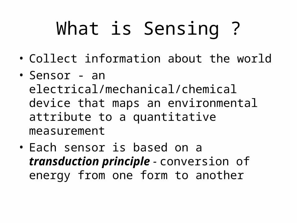
What is Sensing ?
• Collect information about the world• Sensor - an electrical/mechanical/chemical
device that maps an environmental attribute to a quantitative measurement
• Each sensor is based on a transduction principle - conversion of energy from one form to another

Transduction to electronics
• Thermistor: temperature-to-resistance• Electrochemical: chemistry-to-voltage• Photocurrent: light intensity-to-current• Pyroelectric: thermal radiation-to-voltage• Humidity: humidity-to-capacitance• Length (LVDT: Linear variable differential
transformers) : position-to-inductance• Microphone: sound pressure-to-<anything>

Human sensing and organs• Vision: eyes (optics, light)
• Hearing: ears (acoustics, sound)
• Touch: skin (mechanics, heat)
• Odor: nose (vapor-phase chemistry)
• Taste: tongue (liquid-phase chemistry)
Counterpart?

Extended ranges and modalities
• Vision outside the RGB spectrum– Infrared Camera, see at night
• Active vision– Radar and optical (laser) range measurement
• Hearing outside the 20 Hz – 20 kHz range– Ultrasonic range measurement
• Chemical analysis beyond taste and smell• Radiation: , , -rays, neutrons, etc

Electromagnetic SpectrumElectromagnetic SpectrumVisible Spectrum
700 nm 400 nm

Sensors Used in Robot

Solar Cell
Digital Infrared Ranging
Compass
Touch Switch
Pressure Switch
Limit Switch
Magnetic Reed Switch
Magnetic Sensor
Miniature Polaroid Sensor
Polaroid Sensor Board
Piezo Ultrasonic Transducers
Pyroelectric Detector
Thyristor
Gas Sensor
Gieger-MullerRadiation Sensor
Piezo Bend Sensor
Resistive Bend Sensors
Mechanical Tilt Sensors
Pendulum Resistive Tilt Sensors
CDS Cell Resistive Light Sensor
Hall EffectMagnetic Field
Sensors
Compass
IRDA Transceiver
IR Amplifier Sensor
IR ModulatorReceiverLite-On IR
Remote Receiver
Radio ShackRemote Receiver
IR Sensor w/lens
GyroAccelerometer
IR Reflection Sensor
IR Pin Diode
UV Detector
Metal Detector

Sensors used in robot navigation
• Resistive sensors– bend sensors, potentiometer, resistive photocells, ...
• Tactile sensors– contact switch, bumpers…
• Infrared sensors – Reflective, proximity, distance sensors…
• Ultrasonic Distance Sensor• Inertial Sensors (measure the second derivatives of position)
– Accelerometer, Gyroscopes, • Orientation Sensors
– Compass, Inclinometer• Laser range sensors• Vision• Global Positioning System

Classification of Sensors• Internal state (proprioception) v.s. external state
(exteroceptive)– feedback of robot internal parameters, e.g. battery
level, wheel position, joint angle, etc,– observation of environments, objects
• Active v.s. non-active – emitting energy into the environment, e.g., radar,
sonar– passively receive energy to make observation, e.g.,
camera• Contact v.s. non-contact• Visual v.s. non-visual
– vision-based sensing, image processing, video camera

11
• In general, robotic sensors can be divided into two classes:
i. Internal state sensors - device being used to measure the position, velocity and acceleration of the robot joint and/or end-effector. These devices are potentiometer, tachometers, synchros, resolvers, differential transformers, optical interrupters, optical encoders and accelerometer.
ii. External state sensors – device being used to monitor the relationship between the robot kinematics and/or dynamics with its task, surrounding, or the object being manipulated.
Robotic Sensor Classification

12
Sensor Selection/Sensing Taxonomy
• There are many different types of robot sensors available and there are many different parameter measured by these sensors.
• The application process, should be carried out in a top down manner, starting with task requirements, and going through several levels of analysis, eventually leading to the selection of a specific device.
• A taxonomy for sensing to aid this process consists of five levels of refinement leading to sensor selection:
1. Specification of task requirements :eg localization, slippage detection, size confirmation, inspection, defect testing.
2. Choice of modality :eg,vision, force, tactile3. Specification on sensor attributes :eg,output, complexity, discrete or
continuous variable, imaging or non-imaging, local or global4. Specification of operational parameters :eg size, accuracy, cost5. Selection of mechanism :eg switching devices, inductive sensors, CCD
vision imaging

13
•Some tasks requirements features:
•Insertion Monitoring•Assembly Verification•Detection of Reject Parts•Recognition of Part Types•Assembly Test Operations•Check Gripper/Tool Operation•Location & Orientation of Parts•Workspace Intrusion Detection•Check Correct Manipulation of Parts•Analysis of Spatial Relations Between Parts
14
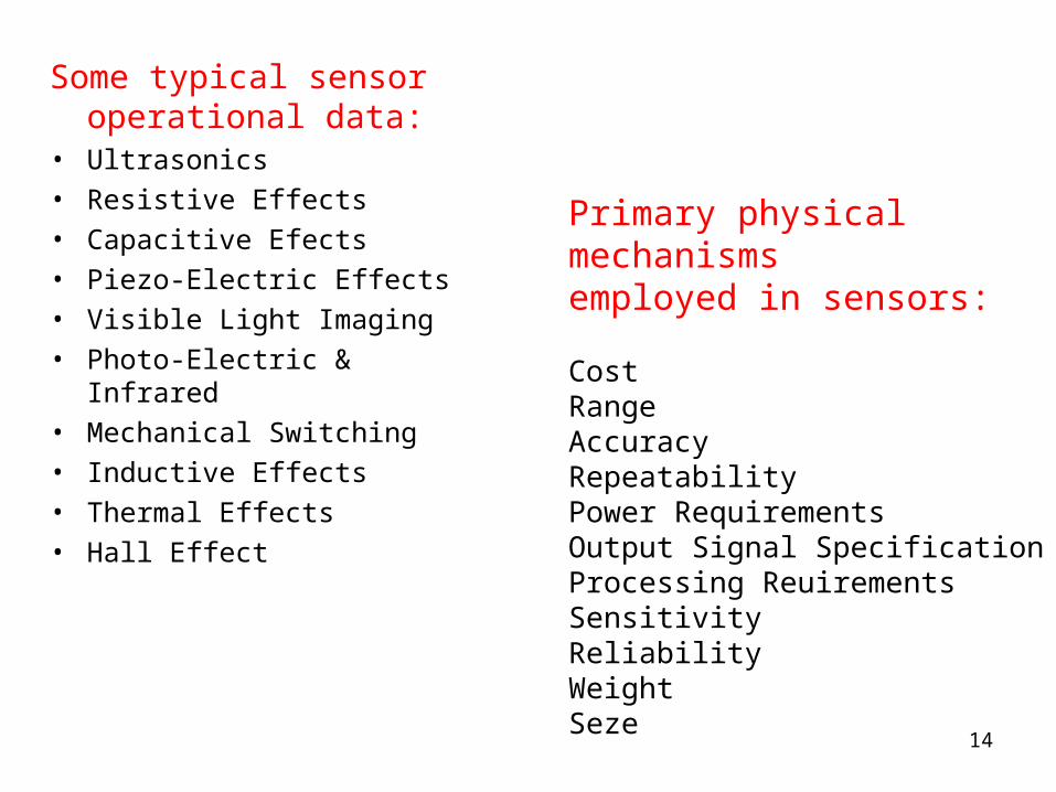
Some typical sensor operational data:
• Ultrasonics• Resistive Effects• Capacitive Efects• Piezo-Electric Effects• Visible Light Imaging• Photo-Electric & Infrared• Mechanical Switching• Inductive Effects• Thermal Effects• Hall Effect
Primary physical mechanisms employed in sensors:
CostRangeAccuracyRepeatabilityPower RequirementsOutput Signal SpecificationProcessing ReuirementsSensitivityReliabilityWeightSeze

SENSORS FOR INDUSTRIAL ROBOTS
Proximity and Range Sensors
Tactile Sensors
Vision Sensors
Miscellaneous Sensors

PROXIMITY AND RANGE SENSORS

I
• It is a technique of detecting the presence or absence of an object with electronic noncontact sensors.
• Typical application of proximity sensors includes:Object detection ש Collision avoidance ש Object verification & counting ש
• Commonly available proximity sensors are:1. Photoelectric/optical sensors
2. Inductive proximity sensors3. Capacitive proximity sensors4. Ultrasonic proximity sensors
17

Bend Sensors• Resistance = 10k to 35k• As the strip is bent, resistance increases
Potentiometers• Can be used as position sensors for sliding mechanisms or rotating shafts • Easy to find, easy to mount
Light Sensor (Photocell)• Good for detecting direction/presence of light • Non-linear resistance• Slow response to light changes
Resistive Sensors
Resistive Bend Sensor
Photocell
Potentiometer
R is small when brightly illuminated

Sensor
Measure bend of a joint
Wall Following/Collision Detection
Weight Sensor
Sensors
Sensor
Applications

Inputs for Resistive SensorsVoltage divider:
You have two resisters, oneis fixed and the other varies,as well as a constant voltage
V
micro
R1
R2
Vsense
Comparator: If voltage at + is greater than at -, digital high out
+-
Binary Threshold
V
VRR
RVsense
21
2
A/D converter
Digital I/O

Infrared Sensors
• Intensity based infrared– Reflective sensors – Easy to implement– susceptible to ambient light
• Modulated Infrared– Proximity sensors– Requires modulated IR signal– Insensitive to ambient light
• Infrared Ranging– Distance sensors– Short range distance measurement– Impervious to ambient light, color and reflectivity of object

Intensity Based Infrared
• Easy to implement (few components)• Works very well in controlled environments• Sensitive to ambient light
time
volta
ge
timevo
ltag
e
Increase in ambient light raises DC bias
Break-Beam sensor
Reflective Sensor

IR Reflective Sensors• Reflective Sensor:
– Emitter IR LED + detector photodiode/phototransistor– Phototransistor: the more light reaching the phototransistor, the
more current passes through it– A beam of light is reflected off a surface and into a detector– Light usually in infrared spectrum, IR light is invisible
• Applications:– Object detection, – Line following, Wall tracking– Optical encoder (Break-Beam sensor)
• Drawbacks:– Susceptible to ambient lighting
• Provide sheath to insulate the device from outside lighting – Susceptible to reflectivity of objects– Susceptible to the distance between sensor and the object
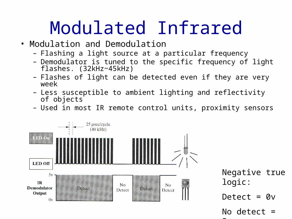
Modulated Infrared• Modulation and Demodulation
– Flashing a light source at a particular frequency– Demodulator is tuned to the specific frequency of light flashes.
(32kHz~45kHz)– Flashes of light can be detected even if they are very week – Less susceptible to ambient lighting and reflectivity of objects– Used in most IR remote control units, proximity sensors
Negative true logic:
Detect = 0v
No detect = 5v

IR Proximity Sensors
• Proximity Sensors: – Requires a modulated IR LED, a detector module with built-in modulation
decoder– Current through the IR LED should be limited: adding a series resistor in
LED driver circuit– Detection range: varies with different objects (shiny white card vs. dull
black object)– Insensitive to ambient light
• Applications:– Rough distance measurement – Obstacle avoidance– Wall following, line following
limiter demodulatorbandpass filteramplifier
comparatorintegrator
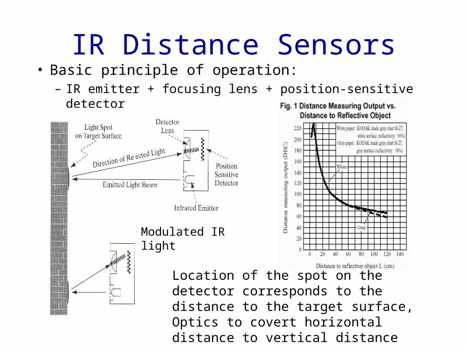
IR Distance Sensors• Basic principle of operation:
– IR emitter + focusing lens + position-sensitive detector
Location of the spot on the detector corresponds to the distance to the target surface, Optics to covert horizontal distance to vertical distance
Modulated IR light
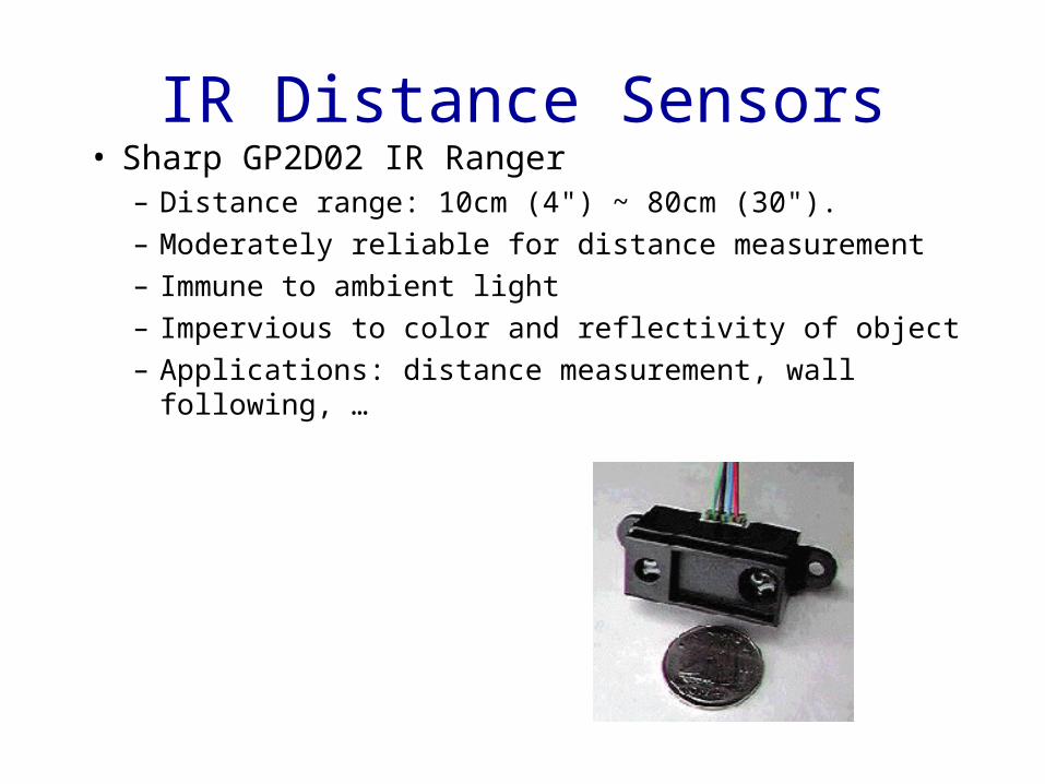
IR Distance Sensors• Sharp GP2D02 IR Ranger
– Distance range: 10cm (4") ~ 80cm (30"). – Moderately reliable for distance measurement – Immune to ambient light – Impervious to color and reflectivity of object– Applications: distance measurement, wall following, …
Range Finder(Ultrasonic, Laser)
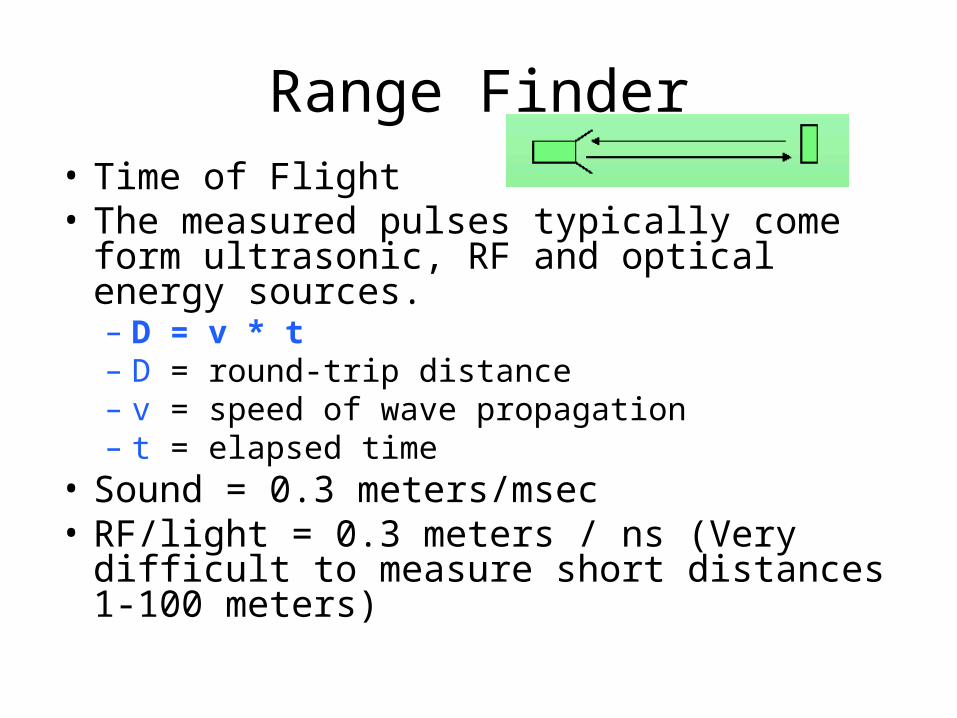
Range Finder• Time of Flight• The measured pulses typically come form
ultrasonic, RF and optical energy sources.– D = v * t– D = round-trip distance– v = speed of wave propagation– t = elapsed time
• Sound = 0.3 meters/msec• RF/light = 0.3 meters / ns (Very difficult to
measure short distances 1-100 meters)

Ultrasonic Sensors• Basic principle of operation:
– Emit a quick burst of ultrasound (50kHz), (human hearing: 20Hz to 20kHz) – Measure the elapsed time until the receiver indicates that an echo is
detected.– Determine how far away the nearest object is from the sensor
D = v * tD = round-trip distancev = speed of propagation(340 m/s)t = elapsed time
Bat, dolphin, …
Ultrasonic Sensors
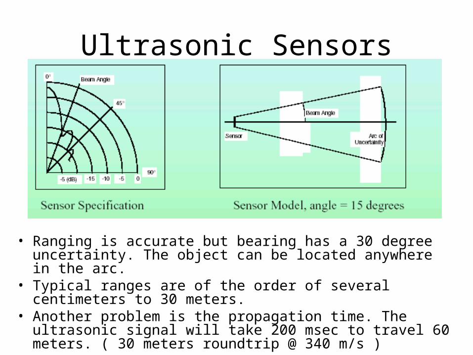
• Ranging is accurate but bearing has a 30 degree uncertainty. The object can be located anywhere in the arc.
• Typical ranges are of the order of several centimeters to 30 meters.
• Another problem is the propagation time. The ultrasonic signal will take 200 msec to travel 60 meters. ( 30 meters roundtrip @ 340 m/s )

Ultrasonic Sensors• Polaroid ultrasonic ranging system
– It was developed for auto-focus of cameras.– Range: 6 inches to 35 feet
Ultrasonic transducer
Electronic boardTransducer Ringing: transmitter + receiver @
50 KHz Residual vibrations or
ringing may be interpreted as the echo signal
Blanking signal to block any return signals for the first 2.38ms after transmission
http://www.acroname.com/robotics/info/articles/sonar/sonar.html

Operation with Polaroid Ultrasonic• The Electronic board supplied has the following I/0
– INIT : trigger the sensor, ( 16 pulses are transmitted )– BLANKING : goes high to avoid detection of own signal– ECHO : echo was detected.– BINH : goes high to end the blanking (reduce blanking
time < 2.38 ms) – BLNK : to be generated if multiple echo is required
t

Ultrasonic Sensors• Applications:
– Distance Measurement– Mapping: Rotating proximity scans (maps the
proximity of objects surrounding the robot)
chair
Robot
chair
Doorway
Scan moving from left to right
Leng
th o
f Ech
o
Scanning at an angle of 15º apart can achieve best results

Noise Issues

Laser Ranger Finder• Range 2-500 meters• Resolution : 10 mm• Field of view : 100 - 180 degrees• Angular resolution : 0.25 degrees• Scan time : 13 - 40 msec.• These lasers are more immune to Dust and
Fog
http://www.sick.de/de/products/categories/safety/

TACTILE SENSORS

• Tactile sensing includes any form of sensing which requires physical touching between the sensor and the object to be sense.
• The need for touch or tactile sensors occurs in many robotic applications, from picking oranges to loading machines. Probably the most important application currently is the general problem of locating, identifying, and organizing parts that need to be assembled.
• Tactile sensor system includes the capability to detect such things as:1. Presence2. Part shape, location, orientation, contour examination3. Contact are pressure and pressure distribution4. Force magnitude, location, and direction5. Surface inspection : texture monitoring, joint checking, damage detection6. Object classification : recognition, discrimination7. Grasping : verification, error compensation (slip, position ,orientation)8. Assembly monitoring
38

• The major components of a tactile/touch sensor system are:
1. A touch surface2. A transduction medium, which
convert local forces or moments into electrical signals.
3. Structure4. Control/interface
39

• It is the transduction method in tactile sensor design which has received the most attention. It is concerned with the change in resistance of a conductive material under applied pressure.
• This technique involves measuring the resistance either through or across the thickness of a conductive elastomer. Most elastomers are made from carbon- or silicon-doped rubber.
40
Resistive
Resistive Tactile Element –Resistance Measured ThroughThe rubber
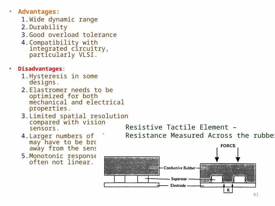
• Advantages:1. Wide dynamic range2. Durability3. Good overload tolerance4. Compatibility with integrated
circuitry, particularly VLSI.
• Disadvantages:1. Hysteresis in some designs.2. Elastromer needs to be optimized
for both mechanical and electrical properties.
3. Limited spatial resolution compared with vision sensors.
4. Larger numbers of wires may have to be brought away from the sensor.
5. Monotonic response but often not linear.
41
Resistive Tactile Element – Resistance Measured Across the rubber

Piezoelectric & Pyroelectric Effects• Piezoelectric effect is the
generation of a voltage across a sensing element when pressure applied to it. The voltage generated is proportionally related to the applied pressure. No external voltage is required, and a continuous analogue output is available from such sensor.
• A pyroelectric effect is the generation of a voltage when the sensing element is heated or cooled.
• Polymeric materials with piezoelectric and pyroelectric properties are appropriate for use with sensors.
42
Piezoelectric/Pyroelectric Effects Tactile element
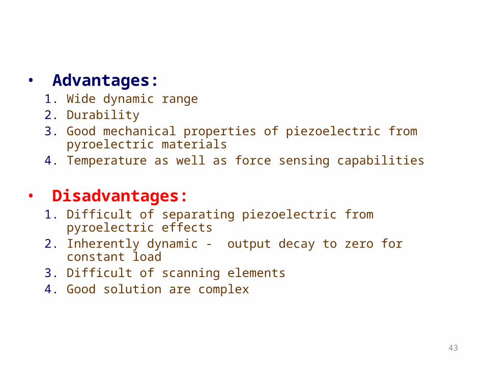
• Advantages:1. Wide dynamic range2. Durability3. Good mechanical properties of piezoelectric from pyroelectric
materials4. Temperature as well as force sensing capabilities
• Disadvantages:1. Difficult of separating piezoelectric from pyroelectric effects2. Inherently dynamic - output decay to zero for constant load3. Difficult of scanning elements4. Good solution are complex
43

CAPACITIVE TECHNIQUE
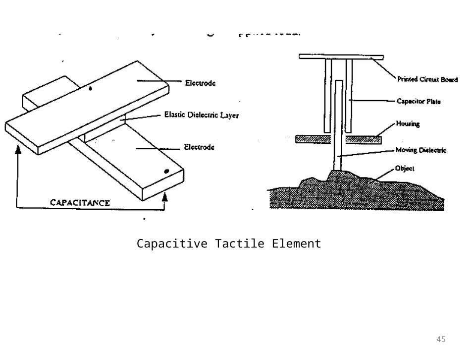
• Tactile sensors within this category are concerned with measuring capacitance, which made to vary under applied load.
• The capacitance of a parallel plate capacitor depends upon the separation of the plates and their area, so that a sensor using an elastomeric separator between the plates provides compliance such that the capacitance will vary according to applied load.
44
45
Capacitive Tactile Element

• Advantages:1. Wide dynamic range2. Linear response3. Robust
• Disadvantages:1. Susceptible to noise2. Some dielectrics are temperature sensitive3. Capacitance decreases with physical size ultimately limiting spatial
resolution.
46

Mechanical Transduction
• A Linear Potentiometer
• Advantages:1. Well known Technology2. Good for probe application • Disadvantages:1. Limited spatial resolution2. Complex for array construction
47
Mechanical TransducerA linear Potentiometer

Magnetic Transduction Methods
• Sensors using magnetic transduction are divided into two basic categories:
Groups together sensors which use mechanical movement to produce change in magnetic flux.
• Advantages:1. Wide dynamic range2. Large displacements possible3. Simple• Disadvantages:1. Poor spatial resolution2. Mechanical problems when
sensing on slopes.
48
Magnetic tactile Element
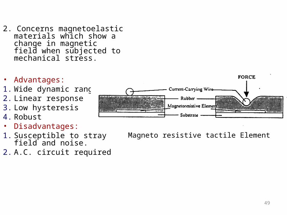
2. Concerns magnetoelastic materials which show a change in magnetic field when subjected to mechanical stress.
• Advantages:1. Wide dynamic range2. Linear response3. Low hysteresis4. Robust• Disadvantages:1. Susceptible to stray field and
noise.2. A.C. circuit required
49
Magneto resistive tactile Element
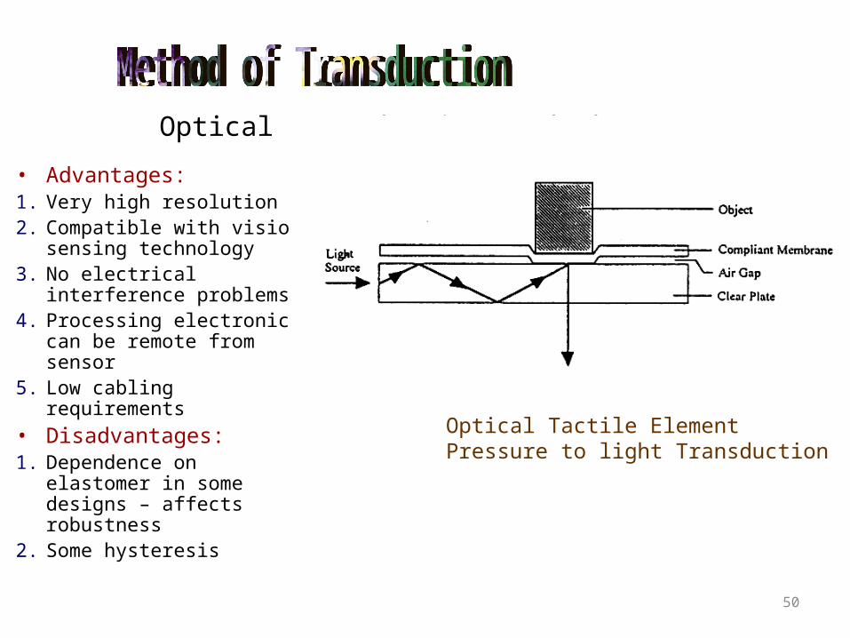
Optical Transduction Methods
• Advantages:1. Very high resolution2. Compatible with vision
sensing technology3. No electrical interference
problems4. Processing electronics can
be remote from sensor5. Low cabling requirements• Disadvantages:1. Dependence on elastomer
in some designs – affects robustness
2. Some hysteresis
50
Optical Tactile ElementPressure to light Transduction

VISION SENSORS
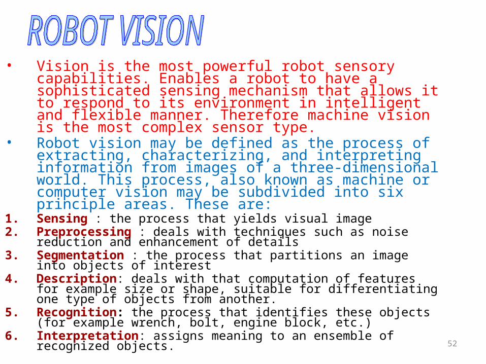
• Vision is the most powerful robot sensory capabilities. Enables a robot to have a sophisticated sensing mechanism that allows it to respond to its environment in intelligent and flexible manner. Therefore machine vision is the most complex sensor type.
• Robot vision may be defined as the process of extracting, characterizing, and interpreting information from images of a three-dimensional world. This process, also known as machine or computer vision may be subdivided into six principle areas. These are:
1. Sensing : the process that yields visual image2. Preprocessing : deals with techniques such as noise reduction and
enhancement of details3. Segmentation : the process that partitions an image into objects of
interest4. Description: deals with that computation of features for example size or
shape, suitable for differentiating one type of objects from another.5. Recognition: the process that identifies these objects (for example
wrench, bolt, engine block, etc.)6. Interpretation: assigns meaning to an ensemble of recognized objects.
52
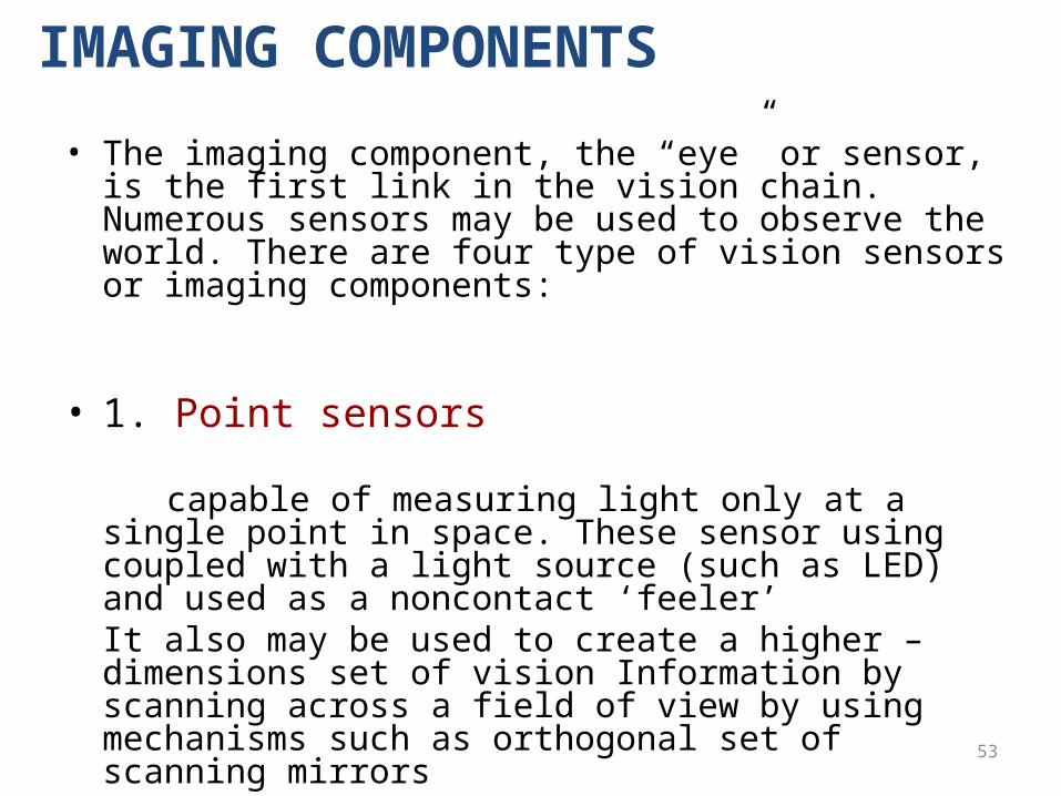
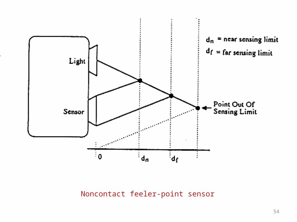
• The imaging component, the “eye” or sensor, is the first link in the vision chain. Numerous sensors may be used to observe the world. There are four type of vision sensors or imaging components:
• 1. Point sensors
capable of measuring light only at a single point in space. These sensor using coupled with a light source (such as LED) and used as a noncontact ‘feeler’ It also may be used to create a higher – dimensions set of vision Information by scanning across a field of view by using mechanisms such as orthogonal set of scanning mirrors
53
IMAGING COMPONENTS
54
Noncontact feeler-point sensor

55
Image scanning using a point sensor and oscillating deflecting mirrors
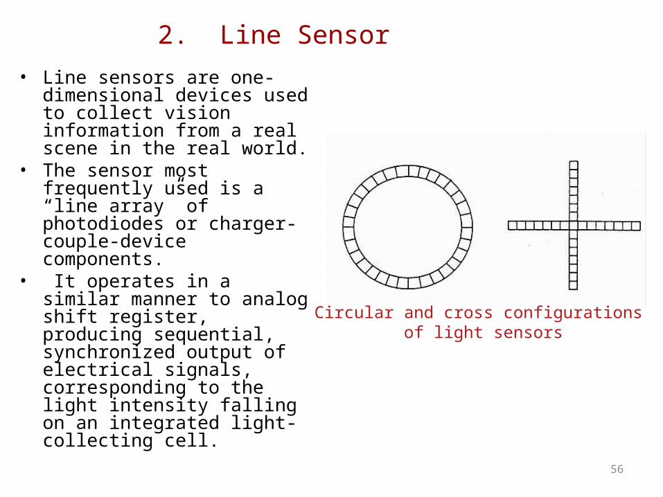
2. Line Sensor• Line sensors are one-dimensional
devices used to collect vision information from a real scene in the real world.
• The sensor most frequently used is a “line array” of photodiodes or charger-couple-device components.
• It operates in a similar manner to analog shift register, producing sequential, synchronized output of electrical signals, corresponding to the light intensity falling on an integrated light-collecting cell.
56
Circular and cross configurations of light sensors
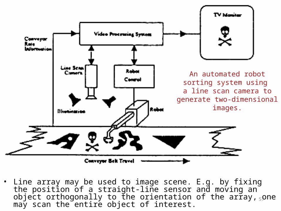
• Line array may be used to image scene. E.g. by fixing the position of a straight-line sensor and moving an object orthogonally to the orientation of the array, one may scan the entire object of interest. 57
An automated robot sorting system using
a line scan camera to generate two-dimensional images.

3. Planar Sensor
• A two dimensional configuration of the line-scan concept. Two generic types of these sensors generally in use today are scanning photomultipliers and solid-state sensors.
• Photomultipliers are represented by television cameras, the most common of which is the vidicon tube, which essentially an optical-to-electrical signal converter.
• In addition to vidicon tubes, several types of solid-state cameras are available. Many applications require the solid-state sensors because of weight and noise factor (solid-state arrays are less noisy but more expensive). This is important when mounting a camera near or on the end-effector of a robot.
58
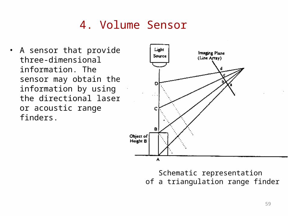
4. Volume Sensor
• A sensor that provide three-dimensional information. The sensor may obtain the information by using the directional laser or acoustic range finders.
59
Schematic representation of a triangulation range finder
IMAGE REPRESENTATION
• From the diagram below. F(x,y) is used to denote the two-dimensional image out of a television camera or other imaging device.
• “x” and “y” denote the spatial coordinates (image plane)• “f” at any point (x,y) is proportional to the brightness (intensity) of the
image at that point.• In form suitable for computer processing, an image function f(x,y) must be
digitized both spatially and in amplitude (intensity). Digitization of the spatial coordinates (x,y) will be known as image sampling, while amplitude digitization is known as intensity or grey-level quantization.
• The array of (N, M) rows and columns, where each sample is sampled uniformly, and also quantized in intensity is known as a digital image. Each element in the array is called image element, picture element (or pixel).
60

Effects of reducing sampling grid size.a) 512x512. b) 256x256. c) 128x128. d) 64x64. e) 32x32.
61
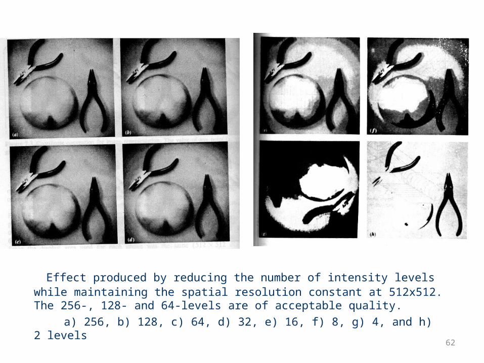
Effect produced by reducing the number of intensity levels while maintaining the spatial resolution constant at 512x512. The 256-, 128- and 64-levels are of acceptable quality.
a) 256, b) 128, c) 64, d) 32, e) 16, f) 8, g) 4, and h) 2 levels62

ILLUMINATION TECHNIQUES• Illumination of a scene is an important factor that often affects the
complexity of vision algorithms.• A well designed lighting system illuminates a scene so that the complexity
of the resulting image is minimised, while the information required for object detection and extraction is enhanced.
• Arbitrary lighting of the environment is often not acceptable because it can result in low contras images, specular reflections, shadows and extraneous details.
• There are 4 main illumination techniques for a robot work space :
63

ILLUMINATION TECHNIQUES
1. DIFFUSE-LIGHTING• This technique is for smooth, regular
surface object. It is used where surface characteristic are important.
• Example:
64
Diffuse-lighting technique

ILLUMINATION TECHNIQUES
2. BACKLIGHTING• Produce black and white image.
This technique suited for applications in which silhouettes of object are sufficient for recognition or other measurement.
• Example:
65
Backlighting technique

ILLUMINATION TECHNIQUES 3. STRUCTURED LIGHTING
• Consist of projecting points, stripes, grids onto work surface.
• This lighting technique has 2 important advantages:
1. It establishes a known light pattern on the work space and disturbances of this indicate the presence of an object, thus simplifying the object detection problems.
2. By analysing the way which the light pattern distorted, it is possible to gain insight into three-dimensional characteristics of the object.
66
Structured lighting technique
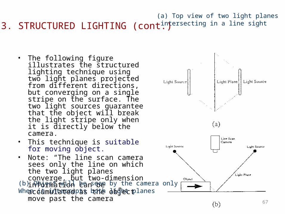
• The following figure illustrates the structured lighting technique using two light planes projected from different directions, but converging on a single stripe on the surface. The two light sources guarantee that the object will break the light stripe only when it is directly below the camera.
• This technique is suitable for moving object.
• Note: “The line scan camera sees only the line on which the two light planes converge, but two-dimension information can be accumulated as the object move past the camera”
67
3. STRUCTURED LIGHTING (cont.)(a) Top view of two light planes intersecting in a line sight
(b) Object will be seen by the camera only When it interrupts both light planes

ILLUMINATION TECHNIQUES
4. DIRECTIONAL LIGHTING
• This method is used to inspection of object surfaces.
• Defects on the surface such as scratches, can be detected by using a highly directed light beam (such as laser beam) and measuring the amount of scatter
68
Directional lighting technique

ROBOT VISION SYSTEM• There are several commercial packages that can be bought for vision processing work.
A typical hardware configuration is shown below.• Based on the technique used, the robotic vision systems can be grouped into the
following major types:1. Binary vision systems 4.Structured light vision systems2. Gray-level vision systems 5.Character recognition vision systems3. Ad hoc special-purpose vision systems
69
Vision system hardware

• A typical system will have facilities for controlling the camera remotely and perhaps interfaces for remote lighting control.
• The main problem with commercial vision packages is that they have to be general purpose in order to be applicable in many situations. This very requirement sometimes means that they are not suitable or are over complicated for a particular robot task in hand.
• In industrial robot world, vision is not used in an exploratory sense but is used to confirm or measure or refine existing known data.
• Whichever commercial vision system one purchases, one is likely to use it for applications such as those listed in the next section.
70

Vision Dev. Tools: Survey
• Commercial products– Matrox: MIL, Inspector– Coreco Imaging: Sapera,
MVTools, WiT– MVTec: Halcon– Euresys: eVision, EasyAccess– AAI: Aphlion
• Free tools– Intel: Open Source Computer
Vision – Microsoft: Vision SDK– XMegaWave: XMegaWave– UTHSCSA: ImageTool
71
Slide borrowed from CAIRO

VISION APPLICATIONS• 1. OBJECT LOCATION
Used in object handling and processing: -Position -Orientation• 2. OBJECT PROPERTIES
Used in inspection, identification, measurement: -Size -Area -Shape -Periphery length / area ratio -Texture -Repetition of pattern -Properties of internal features
• 3. SPATIAL RELATIONSUsed in measurement and task verification -Relative positions -Relative orientations -Occlusions -Alignments -Connectivity
• 4. ACTION MONITORING Used in actuator control and verification: -Direct feedback -Error measurement
-Action confirmation -Inspection -Collision avoidance planning. 72

MISCELLANEOUS SENSORS
73

MISCELLANEOUS SENSORS
• There are several type of sensor that can be used to determine the position of robot joints like potentiometer, optical encoder, Linear Variable Differential Transformer (LVDT) Force & Torque Sensors.
74
POSITION, VELOCITY&
ACCELERATION SENSORS

Potentiometer
• Potentiometer transducers can be used to measure both linear and angular displacement
75
(a) Potentiometer (b) (b) Schematic diagram of the potentiometer

Linear Variable Differential Transformer (LVDT)
• LDVT is a robust and precise device which produce a voltage output proportional to the displacement of a ferrous armature for measurement of robot joints or end-effectors. It is much expensive but outperforms the potentiometer transducer.
76
Linear Variable Differential Transformer (LVDT)

Force & Torque Sensors
• Force transducers are often based on displacement principles. There various type force and torque transducer available commercially
77
A force-measuring device based on a compression spring and LDVT.

78
This figure illustrate a tension load cell. It can be used to measure the force required to pick up heavy load in industry

Force & Torque Sensors
• Force can be measured using piezoelectric principle.
• Figure shows a load washer type piezoelectric force transducer. It is designed to measure axial forces. It is preloaded when manufactured and can measure both tensile and compressive forces.
79
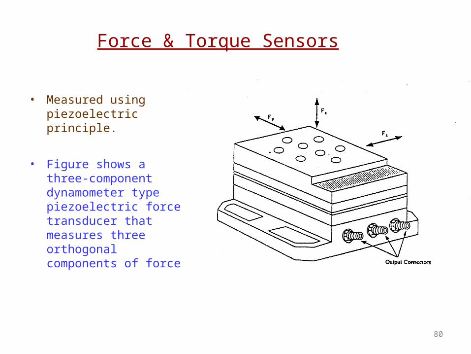
Force & Torque Sensors
• Measured using piezoelectric principle.
• Figure shows a three-component dynamometer type piezoelectric force transducer that measures three orthogonal components of force.
80
Motor Encoder

Incremental Optical Encoders
- direction
- resolution
grating
light emitter
light sensor
decode circuitry
A
B A leads B
• Incremental Encoder:
• It generates pulses proportional to the rotation speed of the shaft.• Direction can also be indicated with a two phase encoder:

Absolute Optical Encoders
Gray Code
• Used when loss of reference is not possible.• Gray codes: only one bit changes at a time ( less uncertainty).• The information is transferred in parallel form (many wires are necessary).
000
001
011
010
110
111
101
100
000
001
010
011
100
101
110
111
Binary

Other Odometry Sensors
• Resolver
• Potentiometer
= varying resistance
It has two stator windings positioned at 90 degrees. The output voltage is proportional to the sine or cosine function of the rotor's angle. The rotor is made up of a third winding, winding C

Inertial Sensors
• Gyroscopes – Measure the rate of rotation independent of the
coordinate frame – Common applications:
• Heading sensors, Full Inertial Navigation systems (INS)
• Accelerometers – Measure accelerations with respect to an inertial frame – Common applications:
• Tilt sensor in static applications, Vibration Analysis, Full INS Systems

Accelerometers
• They measure the inertia force generated when a mass is affected by a change in velocity.
• This force may change – The tension of a string – The deflection of a beam – The vibrating frequency of a mass
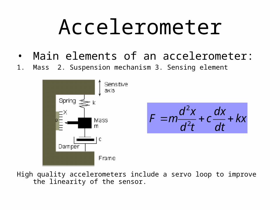
Accelerometer• Main elements of an accelerometer: 1. Mass 2. Suspension mechanism 3. Sensing element
High quality accelerometers include a servo loop to improve the linearity of the sensor.
kxdt
dxc
td
xdmF
2
2

Gyroscopes • These devices return a signal proportional to the
rotational velocity. • There is a large variety of gyroscopes that are based
on different principles

Global Positioning System (GPS)
Space Segment
http://www.cnde.iastate.edu/staff/swormley/gps/gps.html
24 satellites (+several spares)
broadcast time, identity, orbital parameters (latitude, longitude, altitude)

Global Positioning System (GPS)
Space Segment
http://www.cnde.iastate.edu/staff/swormley/gps/gps.html
24 satellites (+several spares)
broadcast time, identity, orbital parameters (latitude, longitude, altitude)

Noise Issues
• Real sensors are noisy• Origins: natural phenomena + less-than-ideal
engineering• Consequences: limited accuracy and
precision of measurements• Filtering:
– software: averaging, signal processing algorithm– hardware tricky: capacitor

Thank you!