1. GENERAL INSTRUCTIONS 4. METHOD OF INSTALLATION
12
Transcript of 1. GENERAL INSTRUCTIONS 4. METHOD OF INSTALLATION

1. GENERAL INSTRUCTIONSThis appliance is designed for storage of food andstorage of frozen food and making ice.
The refrigerators outlined herein have been design certi-fied by A.G.A. under ANSI Z21.19 Refrigerator Standardfor installation in a mobile home or recreational vehicleand are approved by the Canadian Gas Association. Thecertifications are, however, contingent on the installationbeing made in accordance with the following instructionsas applicable.
In the U.S.A., the installation must conform with:
1. National Fuel Gas Code ANSI Z223.1-(latest edition)2. Manufactured Home Construction and Safety
Standard, Title 24 CFR, Part 32803. Recreational Vehicles ANSI A119.2-(latest edition).
The unit must be electrically grounded in accordancewith the National Electric Code ANSI/NFPA 70-(latestedition) when installed if an external alternating currentelectrical source is utilized.
4. Any applicable local code.
In Canada, the installation must conform with:
1. Current CGA B 149 Gas Installation Codes2. Current CSA Standard Z 240.4 GAS-EQUIPPED
RECREATIONAL VEHICLES AND MOBILEHOUSING
3. Any applicable local code
The unit must be electrically grounded in accordancewith the CANADIAN ELECTRICAL CODE C 22 Parts 1and 2.
2. VENTILATIONThe installation shall be made in such a manner as toseparate the combustion system from the living space ofthe mobile home or recreational vehicle. Louver ope-nings must have a minimum dimension of 1/4 inch for airsupply or venting of combustion products.
Proper installation requires one fresh air intake and oneupper exhaust vent. The ventilation kits shown in thisinstruction manual have been certified for use with therefrigerator model listed in the Table. For "Certified VentSystem Kits" see Section B. The ventilation kits must beinstalled and used without modification. An openingtoward the outside at floor level in the refrigerator com-partment must be provided for ventilation of heavier-than-air fuel gases. The lower vent of the recommendedkits is provided with properly sized openings. The flow ofcombustion and ventilation air must not be obstructed.The lower side vent is fitted with a panel which providesan adequate access opening for ready serviceability ofthe burner and control manifold of the refrigerator. Thisshould be centered on the back of the refrigerator.
3. CERTIFIED INSTALLATIONCertified installations require one upper side vent andone lower side vent.
For certified vent system kits, see Section B.For further information, contact your dealer or distributor.
4. METHOD OF INSTALLATION
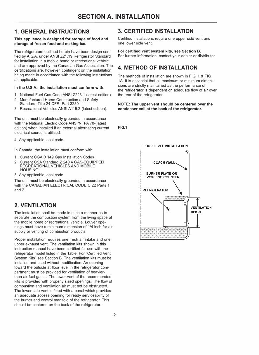
The methods of installation are shown in FIG. 1 & FIG.1A. It is essential that all maximum or minimum dimen-sions are strictly maintained as the performance ofthe refrigerator is dependent on adequate flow of air overthe rear of the refrigerator.
NOTE: The upper vent should be centered over thecondenser coil at the back of the refrigerator.
FIG.1
SECTION A. INSTALLATION
2

FIG.1a
5. VENTILATION HEIGHTSRefer to FIG 1 & FIG. 1A., Pages 1 & 2
Installation with * Minimum Ventilation Upper side vent Height �N�And lower side vent
REFRIGERATOR INCHES MM
RM 4223Metal Side Vents 21.0 533(2) RM 183 Vents
RM 4223Plastic Side Vents(1) 3107560.041 22.0 558.8(1) 3107560.009
* These dimensions represent the minimum height allowable. It is recommended the Upper Vent be located to the maximum possible height of the vehicle for optimum performance in warmer climates.
6. CLEARANCESMinimum clearances in inches to combustible materialsare:
G: Top 0"
K: Side 0"
L: Bottom 0"
M: Rear 9/32"
N: See NOTE
P: See NOTE
NOTE: Clearance "M" is between the rearmost part ofthe refrigerator and the wall behind the refrigerator.
NOTE: Clearance "N" is the distance between the bot-tom of the lower vent to the top of upper side vent. Forventilation height, refer to Section A. Installation, Item 5.Ventilation Heights. See FIG. 2.
Surfaces directly above and sides adjacent to theflue outlet must be of, or covered with, fireproofmaterial. See FIG. 2.
NOTE: Clearance "P" over top of unit condenser fins is1/4 inch. This is the minimum height which can be allo-wed over the condenser fins. Whenever possible, increa-se this height by up to 11 inches; the more ventilationyou provide, the better the performance you can expectfrom the refrigerator.
Fig. 2
3

7. INSTALLING REFRIGERATOR IN ENCLOSURE
NOTE: DO NOT install the appliance directly on car-peting. Carpeting must be removed or protected by ametal or wood panel beneath the appliance, whichextends at least the full width and depth of the appli-ance.
The dimensions shown in FIG.3 will giveyou adequate space for service and pro-per installation.
FIG. 3
RM 4223 Overall Installation Recess Distance between
Dimensions Dimensions Dimensions Top of condenser and
Top of refrigerator
Vent Height Width Depth Height Width Depth Height Width Depth
Type A B C h w d H W D e
Dual Metal (inches) 21-7/32 21-5/32 25-6/32 20-21/32 19-11/32 23-23/32 20-29/32 19-9/16 24 1/4�
Side Vents (mm) 539 537 641,5 524,5 491 602,5 530,5 497 610 6
Dual Plastic (Inches) 21-7/32 21-5/32 25-6/32 20-21/32 19-11/32 23-23/32 20-29/32 19-9/16 *24 1/4�
Side Vents (MM) 539 537 641,5 524,5 491 602,5 530,5 497 *610 6
* Depth �D� Dimensions Requirement with Plastic Vent System is Dependant on Vehicle Side Wall Thickness. If the Vehicle Side Wall Thickness is less than
1,5 inches ( 38mm ), the Recessed Depth Dimensions will be required to be Increased Proportionally to the Vehicle Wall Thicknes.
A. INSTALLATIONThe refrigerator must be installed in a substantial enclo-sure and must be level. When installing the refrigeratorin the enclosure, all areas within the recess in which therefrigerator is installed must be sealed from the livingspace.
Make sure that there is a complete seal between thefront frame of the refrigerator and the top, sides and bot-tom of the enclosure. A length of sealing strip is appliedto the rear surface of the front frame for this purpose,see FIG. 4. The sealing should provide a complete isola-tion of the appliance's combustion system from thevehicle interior.
Note: Be careful not to damage the sealing strip whenrefrigerator is put in place.
4
FIG. 4

B. SECURING REFRIGERATOR IN ENCLOSURE
The refrigerator is installed in the enclosure with eightscrews. Six screws are in the front frame and two are inthe plate on the rear. See FIG. 5.
NOTE: Push refrigerator into enclosure until front frameis tight against the cabinet. First, secure the frame tocabinet with six screws. Second, install the two screwsto the floor at the rear of the refrigerator.
Failure to follow the sequence in securing the refrigeratorin the enclosure can cause leakage between the frameand cabinet. Any space between the counter, storagearea or ceiling and top of the refrigerator should beblocked. The heat produced at the rear of the refrigeratorwill become trapped in this space, making the top of therefrigerator hot and reducing the efficiency.
The dimensions shown in FIG. 3 will give you adequatespace for service and proper installation.
8. GAS CONNECTIONHook-up to the gas supply line is accomplished at themanual gas shutoff valve, which is furnished with a 3/8"SAE (UNF 5/8" - 18) male flare connection. Always usea backup wrench when connecting the gas supply line tothe gas inlet fitting. All completed connections should bechecked for leaks with a noncorrosive leak detector.(See FIG. 6 - Gas inlet fitting may have a different orien-tation than shown).
The gas supply system must incorporate a pressureregulator to maintain a supply pressure of not more than13.5 inches water column, static (no load).
When testing the gas supply system at test pressures inexcess of 1/2 psig, the refrigerator and its individualshutoff valve must be disconnected from the gas supplypiping system.
When testing the gas supply system at pressures lessthan or equal to 1/2 psig, the appliance must be isolatedfrom the gas supply piping by closing its individualmanual shutoff valve.
In case detailed instructions on the installation andconnection to the gas supply are required, contact yourdealer or distributor.
5
FIG. 5
FIG. 6
LP GASCYLINDER
PRESSUREREGULATOR
TOREFRIGERATOR
GAS INLETFITTING
! WARNINGDO NOT use a flame to check for gas leaks.

9. TESTING LP GAS SAFETYSHUTOFF
The gas safety shutoff must be tested after the refrigera-tor is connected to LP gas supply.
To test the gas safety shutoff, proceed as follows:
A. Start the refrigerator according to the instructions for LP Gas Operation. See "Section C. Operation Instructions."
B. Check that the gas flame is lit. Allow it to burn a few minutes to ensure a full, stable flame.
C. Turn the gas safety valve (D, FIG. 8) to the "OFF" position. Within 1-2 minutes the gas safety device within the valve should automatically close. An audible "click" from the valve may be heard.
D. Turn the gas safety valve to the "ON" position (D, FIG. 8).
E. Without pushing in the knob (D, FIG. 8) of the gas safety device, apply a commercial leak detection solution to the burner jet. No bubbles should appear. Bubbles indicate a gas leak and the safety valve mustbe replaced by a qualified serviceman.
F. Rinse the burner jet with water. Light the burner and allow it to burn for five minutes.
10. 120 VOLT AC ELECTRICALCONNECTION
The refrigerator is equipped with a three-prong (groun-ded) plug for protection against shock hazards, andshould be plugged directly into a properly groundedthree-prong receptacle. DO NOT cut or remove the gro-unding prong from this plug. The power cord should berouted to avoid direct contact with the burner cover, fuelcover or manual gas shutoff valve knob.
11. 12 VOLT DC CONNECTIONThe 125 watt heating element operates the cooling unitwhen the refrigerator is connected to the battery of thevehicle. It has a current rating of about 10.5 amps; there-fore, the wiring from the battery to the refrigerator mustbe of heavy enough gauge to carry this load satisfactori-ly without undue voltage drop. To ensure this, the mini-mum size of wire to be used is 14 A.W.G. The terminalblock for connecting the 12V supply cable to the batteryis positioned at the lower lefthand corner of the rear side(G, FIG. 8). From this terminal, the connection to thebattery should be made using ring-type clamps withtightening bolts to ensure good contact with the batteryterminals. Polarity is not important, therefore it does notmatter which wire leads to which battery terminal.
DO NOT connect lights or any other electrical com-ponents to the same circuit that is used by the refri-gerator.
FUSE
A 12 amp (continuous rating) fuse should be incorpora-ted in the wiring of the DC supply, as near to the batteryas possible. The fuse must be in the side of the wiringwhich is not connected to the chassis. For example, ifthe vehicle has a negative ground, the fuse must be inthe positive side of the wiring.
12. CHANGING DOOR HINGES FROM ONE SIDE TO THE OTHER
If required, the door hinges can be moved to the opposi-te side. Reverse the door hang in the following way:
A. Unscrew the upper hinge pin, taking care not to lose the set of washers and bushings.
B. Lift the door from the lower hinge pin. If decorative door panel is to be installed, proceed to Step 13.
C. Unscrew the pin and mount it on the opposite side hinge.
D. Unscrew the travel catch and mount it on the opposite side.
E. Change the cover plate and travel lock plate in top of door frame to opposite side. Use a screwdriver to press down on one edge of the cover plate. The opposite edge will rise above the frame. Use a knife blade under the raised edge to pop it out. See FIG. 7.Use needle-nosed pliers to carefully lift lock plate out of door frame. See FIG. 7.
F. Replace door on lower hinge pin. Replace upper hinge pin and bushings removed in Step A.
G. Check that the door closes properly and seals all around.
6
IMPORTANT:
To prevent the refrigerator from being left on anddraining the battery when the vehicle's engine is notrunning and charging the battery, it is recommendedthat an automatic cutout relay be installed betweenthe battery and the refrigerator toggle switch so thatthe refrigerator will not draw current when thevehicle ignition is switched off. Alternatively, a suita-ble plug and receptacle should be installed in the12V supply line so that the refrigerator can be dis-connected from the supply, as necessary.
FIG. 7

13. INSTALLATION OF DECORATIVEDOOR PANEL
The door panel can easily be mounted. The dimensionsof the panel must be:
Height 19-3/4"Width 17-27/32"Thickness Up to 1/8"Weight 49 lbs.
A. Remove the door. See Section 12.B. Remove the lower trim molding. (NOTE: Trim molding
is not installed on new units in cartons)C. Fit the new panel in place and slide it up as far as
possible.D. Fit the trim molding back in place.
SECTION B. CERTIFIED VENT SYSTEMS
VENT KIT OPTIONS COMPONENTS PART NO.
DUAL METAL SIDE * RM 183 Upper Metal Side Vent 8030211.332 VENTS * RM 183 Upper Metal Side Vent 8030211.332
** Power Ventilator Optional 3108705.751
DUAL PLASTIC SIDE * Upper Plastic Side Vent 3107560.041VENTS * Lower Plastic Side Vent 3107560.009
** Power Ventilator Optional 3108705.751* Vent System Requires One Each.** Alternative instructions forwarded with ventilator kit. Used in conjunction with
upper and lower side vents at minimum vent heights for optimum performance.
SECTION C. OPERATING INSTRUCTIONS
1. IMPORTANCE OF LEVELING AREFRIGERATOR
In an absorption refrigerator system, ammonia is lique-fied in the finned condenser coil at the top of the refrige-rator. The liquid ammonia then flows into the evaporator(inside the freezer section) and is exposed to a circula-ting flow of hydrogen gas, which causes the ammonia toevaporate, creating a cold condition in the freezer.
The tubing in the evaporator section is specifically slo-ped to provide a continuous movement of liquid ammo-nia downward by gravity through this section. If therefrigerator is operated when it is not level and thevehicle is not moving, liquid ammonia will accumulate insections of the evaporator tubing. This will slow the cir-culation of hydrogen and ammonia gas, or in severecases, completely block it, resulting in a loss of cooling.
Remember to level the vehicle when stopping for morethan an hour, otherwise the cooling unit could be perma-nently damaged due to overheating if it is left "ON".
When the vehicle is moving, the leveling is not critical asthe rolling and pitching motion of the vehicle will pass toeither side of level, keeping the liquid ammonia fromaccumulating in the evaporator tubing.
7

2. CONTROLSThe gas and electric controls are located at the rear ofthe refrigerator and are accessible through the lowervents in the outside wall of the vehicle. See FIG. 8.
A = DC ON/OFF SWITCH
B = AC ON/OFF SWITCH
C = ELECTRIC THERMOSTAT
D = GAS ON/OFF VALVE
E = PIEZO IGNITER
F = GAS THERMOSTAT
G = DC TERMINAL BLOCK
H = GAS INLET FITTING
3. OPERATING INSTRUCTIONSA. LP GAS OPERATION
After initial installation, servicing, or changing gas cylin-ders, etc., the gas line may contain some air whichshould be allowed to escape by briefly turning on therefrigerator or other gas appliances. This will ensure thatthe flame lights immediately. See FIG. 8 for control locati-on and identification.
1) Open the shutoff valve of the gas bottle. Check that there is enough gas.Open any on-board shutoff valvewhich is in the gas line to the refrigerator.
2) Open the lower vent at the rear of the refrigerator on the outside of the vehicle, and switch the electrical toggle switches A and B to the "OFF" position.
3) Turn the gas thermostat control (F) to the highest setting.
4) Depress the knob (D) of the flame failure device, turn it to position �ON�, and hold it down while depres-sing the piezo igniter button (E) several times in quicksuccession (a click should be heard each time it is depressed).
5) Keep the knob depressed for a further 10-15 seconds.
6) Release the knob and check for flame by looking through the opening in the metal burner cover.
7) If the burner has not lit, repeat the lighting procedure.If the burner fails to light within a couple of attempts, contact a qualified technician or your dealer.
NOTE: The refrigerator has a flame failure devicewhich will automatically shut off the gas to the bur-ner if the flame is blown out. While the knob (D) isbeing held in, this device is temporarily inoperative.
8) If the ambient temperature is above 80°F and/or the door of the refrigerator is opened frequently the knob (F) should be left in higher position.
9) To terminate gas operation, turn knob (D) to the "OFF" position.
8
DO NOT attempt to operate the refrigerator byboth gas and electricity at the same time. Alwaysensure that one method of operation is turned offbefore using the alternate energy source.
FIG. 8
CONTROLSRM 4223
B A
C
FD
E
H
G

B. ELECTRIC OPERATION12V DC / 120V AC OPERATION
In the case of the RM4223, the refrigerator works conti-nuously on DC operation (no thermostat control).
On AC operation, the temperature is controlled by a ther-mostat. The thermostat knob (C, in FIG. 8) should be setto position 4-5 in normal working conditions. If theambient temperature is high and/or fresh food is put intothe refrigerator you may set the refrigerator to a highersetting.
If you wish a higher temperature in the cooling compart-ment, set the knob to a lower position.
3. TO TERMINATE ELECTRIC OPERATION
To terminate electric operation, turn switches (A and B)to the "OFF" position.
NOTE: NEVER OPERATE THE REFRIGERATOR ONMORE THAN ONE ENERGY SOURCE AT A TIME.
4.HOW TO USE THE REFRIGERATORA. FOOD STORAGE COMPARTMENT
The storage compartment is completely closed andunventilated, which is necessary to maintain the requiredlow temperature for food storage. Consequently, foodshaving a strong odor or those that absorb odors easilyshould be covered. Vegetables, salads, etc. should becovered to retain their crispness. The coldest positions inthe refrigerator are under the cooling fins and at thebottom of the refrigerator. The warmer areas are on theupper door shelves. This should be considered whenplacing different types of food in the refrigerator.
The refrigerator is designed for the storage of freshfoods, milk, etc. It is not intended for the storage of fro-zen food. The internal volume of the refrigerator is 2,5cubic feet, net.
NEVER PUT HOT FOOD INTO THE REFRIGERATOR.
Avoid using large dishes and do not stack food or foodcontainers too closely as this interferes with the circulati-on of cold air within the cabinet.
If possible, start the refrigerator on gas or AC the daybefore it is to be used, to allow time for the interior to becooled. It is then preferable to load the refrigerator withfood which has been precooled in your householdrefrigerator, or in the market.
Before moving the vehicle, make sure that all containersare tightly covered to avoid spills. If required, crumpledpaper may be packed between bottles and other items toprevent shifting while traveling.
Engage the travel catch at the top of the front corner ofthe door before moving the vehicle.
B. DEFROSTING
To defrost, take out any food, etc. then turn off the gasvalve or switch of the DC/AC supply to the refrigerator.Leave the refrigerator door open and place a suitabledish or other receptacle under the evaporator to catchthe defrost water.
When all the frost has melted, any remaining drops ofwater in the refrigerator should be wiped up with a cleancloth.
DO NOT use a hot air blower. Permanent damagecould result from warping the metal or plastic parts.DO NOT use a knife or an ice pick, or other sharptools to remove frost from the freezer shelf.
9
Most LP gas appliances used in recreational vehicles are vented to the outside of the vehicle.When parked close to a gasoline pump, it is possi-ble that the gasoline fumes could enter this typeof appliance and ignite from the burner flame,CAUSING A FIRE OR AN EXPLOSION.
FOR YOUR SAFETY, it is recommended that all LPgas appliances which are vented to the outsideshould be shut off when refueling.
The refrigerator must be shut off during refueling.
! WARNING
! CAUTION

E. CLEANING
Cleaning the refrigerator is usually done after it is defro-sted or put into storage. To clean the interior of the refri-gerator, use lukewarm water and a mild dishwashingdetergent. Use only warm water to clean the finned eva-porator, gaskets, ice trays and shelves. NEVER usestrong chemicals or abrasives to clean these parts as theprotective surfaces will be damaged. It is important toalways keep the refrigerator clean.
F. SHUTOFF (STORAGE PROCEDURE)
Place the toggle switches for DC and AC operation tothe "OFF" position or turn the gas valve to position"OFF", as applicable. See FIG. 8.
When not in use, the refrigerator should be emptied, cle-aned and dried and the door left open so that fresh aircan circulate inside.
The travel latch placed in the second hole will hold thedoor ajar and allow air to circulate.
10
DO NOT store explosive substances in the refrigera-tor, such as cigarette lighter gas, petrol, ether or thelike.
SECTION D. MAINTENANCE & SERVICETIPS FOR THE SERVICE TECHNICIAN
The user should be aware of service that must be doneon a regular schedule to keep the refrigerator operatingproperly. The service should only be performed by aqualified technician who is familiar with LP gassystems and refrigerators.
1.REFRIGERATOR REMOVALBefore working on, or removing the refrigerator, makesure the electrical supply (AC and DC) is turned OFFbefore leads are disconnected. Shut off the gas supply.Disconnect and cap the gas supply line. Loosen thescrews anchoring the refrigerator to the enclosure andslide the refrigerator out of the compartment.
Replacement is the reverse of removal. Check allconnections for gas leaks.Refer to Section A, Item 1through 13 of Installation Instructions.
2. PERIODIC MAINTENANCETo keep a Dometic refrigerator operating efficiently andsafely, periodic inspection and cleaning of several com-ponents once or twice a year is recommended.
A. It is important to keep the area at the back of the refri-gerator clean. Check the lower vent, upper vent and area between these openings for any obstructionssuch as bird/insect nests, spider webs, etc. Clean the coils on the back of the refrigerator. Use a soft bristled brush to dust off the coils..
NOTE: AVOID SPRAYING WATER THROUGH THEREFRIGERATOR VENTS WHEN WASHING THE RV.
It is important to keep the refrigerator vent area free from combustible material, gasoline and other flammable vapors or liquids.
B. Check all connections in the LP gas system (at the back of the refrigerator) for gas leaks. The LP gas supply must be turned on. Apply a noncorrosive bubble solution to all LP gas connections. The appearance of bubbles indicates a leak and should be repaired immediately by a qualified serviceman who is familiar with LP gas systems and refrigerators.
DO NOT USE A FLAME TO CHECK FOR GAS LEAKS.
! WARNING
! CAUTION

C. Examination and Cleaning of Flue, Burner and Jet
Once or twice a year, look through the opening (see FIG.9) in the burner box and examine the appearance of theburner flame which should be predominantly blue incolor when the gas thermostat knob is set to its highestposition. (Refer to FIG. 10).
If this is not the case, clean the flue, burner, jet, etc. (seesection D and E).
D. Cleaning of Burner, Burner Jet (Refer to FIG.11)
Proceed as follows:
1) Turn off the gas at the gas bottle.2) By using a phillips screwdriver, remove the screw (B)
and carefully withdraw the burner cover box. Clean the inside of the box of soot and other deposits.
3) To clean the burner, unscrew the screw (C) that fixes the burner on the boiler tube and be careful in order not to lose the washer.
4) Clean the inside of the burner.5) To examine and eventually clean the burner jet,
unscrew the gas pipe union (K) and pull out the burner jet (L).
6) Clean the jet by washing it in alcohol and blowing it through with air.
DO NOT use a wire or pin when cleaning the burner jet as damage can occur to the precision opening. This can cause damage to therefrigerator or create a fire hazard.
NOTE: The jet fitted to this refrigerator is a size "43" which is suitable for use on propane gas at 11 inches water column. The orifice in the jet is very small and must never be cleaned by means of a pin or similar instrument as this would damage the orifice. It must only be cleaned as described above.
7) Reassemble the components in the reverse order to that described above.
E. CLEANING OF FLUE TUBE, FLUE BAFFLEProceed as follows:
1) To clean the flue tube and the flue baffle, it is necessary to withdraw the refrigerator out of the recess. See Section D, Item 1.
2) By using a phillips screwdriver, remove the screw (B, in FIG. 11) and carefully withdraw the burner cover box.
3) Place a piece of paper or cloth between the boiler tube (E, in FIG. 11) and the burner assembly, to catchfalling deposits.
4) Remove the "T-piece" (A, in FIG. 12) at the top of the flue by unscrewing the screw (B, in FIG. 12) that fixes it to the flue pipe.
5) Carefully takeout the flue baffle (C, FIG. 12) and clean.
6) Clean the flue tube of soot, etc. with the aid of a special flue brush, available from your supplier.
11
FIG. 9
FIG. 10 CLEAR BLUE COLOR OF FLAME
FIG. 11
FIG. 12
OPENING INBURNER BOX
! CAUTION

7) Reassemble the components in the reverse order to that described for removal, taking care to remake the gas connections soundly, and not forgetting to refit the flue baffle.
8) Reinstall the refrigerator in its recess. Connect the gas and electrical supplies, and check for gas leaks. Light the burner and check the appearance of the flame to ensure that it is predominantly blue (when the thermostat is at "HIGH"), then leave the refrigerator on "test" for at least an hour.
3. TROUBLESHOOTINGIf the refrigerator fails to work, check the following pointsbefore calling a service technician:
A. Instructions for STARTING THE REFRIGERATOR, Section C, have been followed.
B. The refrigerator is level.C. If it is possible to start the refrigerator on any of the
connected sources of energy.D. If the refrigerator fails to work on GAS, check:
1) That the gas bottle is not empty.2) That all LP Gas valves in the supply line to the
refrigerator are open.
NOTE: The following checks should be performedonly by a qualified technician.
3) That sparks are generated by the piezo ignitor.4) That the flame continues to burn after releasing
the knob of the flame failure device (B, in FIG.8).If not, the thermocouple may be loose or defective.
12
E. If the refrigerator fails to work DC, check:1) That the DC supply is connected to the
refrigerator.2) That the fuse on the DC supply is intact.3) That the DC switch is set to the "ON" position
(A, in FIG. 8).
F. If the refrigerator fails to work on AC, check:
1) That the AC supply is connected to the refrigerator.
2) That the fuse on the AC supply is intact.3) That the AC switch is set to the "ON" position.4) That the AC thermostat is not set to the "0"
position.
G. If the refrigerator is not cold enough it may be because:
1) The ventilation is inadequate, because of reduced area of the ventilation passages (partial blockage of grilles from wire mesh, etc.).
2) The evaporator is frosted up.3) The temperature control setting is incorrect.4) The gas pressure is incorrect. Check the
pressure regulator.5) The ambient temperature is too high.6) Too much warm food is loaded at one time.7) The door is not properly closed or the magnetic
sealing strip is defective.
All of the previous instructions are to be followed closely. This refrigerator is
quality guaranteed; however, we are not responsible for any failures caused by
improper adjustments and unfavorable installation conditions. If assistance is
required, contact the service point or distributor service department.