
1 Flow Identification Assume you want to guarantee some type of quality of service (minimum...
14
1 Flow Identification Assume you want to guarantee some type of quality of service (minimum bandwidth, maximum end-to-end delay) to a user Before you do that, you have to distinguish the packets of one “user” from another “user”, since they have different requirements (bandwidth, delay) How to do this distinction? We will call a flow to be the sequence of packets generated by one user in one application.
-
Upload
simon-parks -
Category
Documents
-
view
213 -
download
0
Transcript of 1 Flow Identification Assume you want to guarantee some type of quality of service (minimum...

1
Flow Identification
Assume you want to guarantee some type of quality of service (minimum bandwidth, maximum end-to-end delay) to a userBefore you do that, you have to distinguish the packets of one “user” from another “user”, since they have different requirements (bandwidth, delay)How to do this distinction?We will call a flow to be the sequence of packets generated by one user in one application.

2
Flow Identification Continued…
How to separate packets of one user and another?Perhaps look at addresses:
Each packet has a source and destination addressSeparate packets according to (source,destination), i.e., one packet queue per pair
How to quickly do this separation?• I.e., if a packet is received, to which queue I
should add it?

3
Flow Identification, search tree
How about a search tree, indexed by (S,D)
Searching takes multiple steps (O log N, N is the number of queues), too slow
4
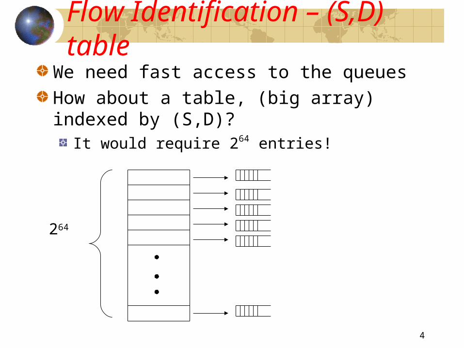
Flow Identification – (S,D) table
We need fast access to the queuesHow about a table, (big array) indexed by (S,D)?
It would require 264 entries!
264
5
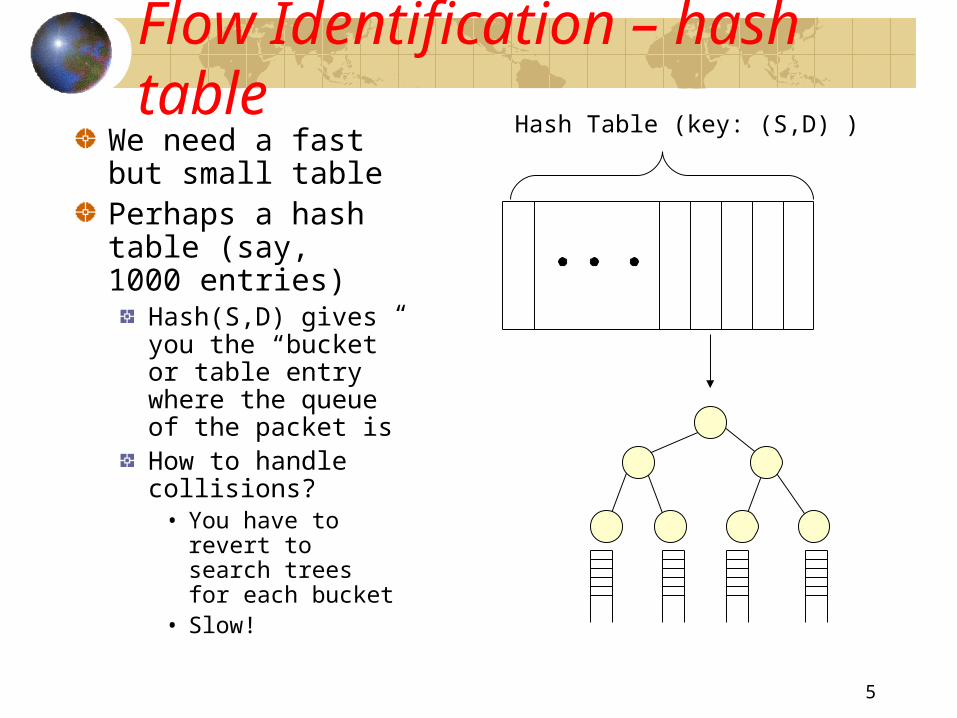
Flow Identification – hash tableWe need a fast but small tablePerhaps a hash table (say, 1000 entries)
Hash(S,D) gives you the “bucket” or table entry where the queue of the packet isHow to handle collisions?
• You have to revert to search trees for each bucket
• Slow!
Hash Table (key: (S,D) )

6
Flow Identification – flow labelWe still need a fast but small table
Say, 1000 entries
Each flow can have a label that is used as an index into that table.Note that there are more than 1000 flows in the world
But a single router may be involved in only about 1000 flows at a time
Hence, flow labels could be local to the router
These are known as “virtual circuits”BTW, they are not used in the Internet (in general)
7
Virtual Circuit Switching
Also referred as connection-oriented model.
Explicit connection setup (and tear-down) phase
All packets follow same route as the setup message route.
Resources may be reserved along this path
The telephone network performs something similar for voice calls

8
Each virtual circuit (VC) (i.e., flow) has a unique virtual circuit identifier (VID) in each switch of its path
It is determined locally at the switch and is chosen independently of other values along the path.
No two VC’s on the same link (port, interface) can use the same VID
Note: VID's are reused periodically, since they are bounded, VID : 0 .. v-1 for some constant v
Virtual Circuit ID’s
Two circuits:one from E to Fanother from A to B
vid = 9
vid = 10 vid = 2
vid = 11
vid = 29
vid = 100
Host A
Host E Host F
Host B
Switch 1 Switch 2

9
Each switch has a VC table
Table has an entry for each virtual circuit going through it
Contains (at least):• Input interface (port number, link number, or whatever
you want to call it)• Input VID• Output interface• Output VID
Virtual Circuit Table
vid = 9
vid = 10 vid = 2
vid = 11
Input Port
Input VID
Output Port Output VID
0 10 2 2
1 9 2 11
Input Port 0
Input Port 1
Output Port 2
• Packets carry the VID in their header
• The pair (input port, VID) can be used as an index into the table
• The table has n*v rows, n = # ports

10
Virtual Circuit (VC) set-up or signaling phase:
Source sends setup() message towards destination.
• Note that forwarding tables are necessary for the setup message, just like in datagram routing !!!!
Destination replies back with ack() .
All the switches along the path between source and destination create an entry in their virtual circuit table
Data Transfer Phase:
• Switches use Virtual Circuit Tables to forward data.
Virtual Circuit Switching (steps)

11
VC: Setup or signaling Phase
0
13
2
0
1 3
2
0
13
2
Switch 3 Host B
Switch 2
Host A
Switch 1
Host C
Host EHost F
Host G
Host H
In. Int. In. VCI Out. Int. Out VCI.
2 5 1 11
In. Int. In. VCI Out. Int. Out VCI.
3 11 0 7
In. Int. In. VCI Out. Int. Out VCI.
0 7 3 4
Switch 2 VC Table
Switch 3 VC Table
Setup( ) message Ack() Message
B
B
B
B
B 4
B 7
B 11
B 5
Switch 1 VC Table

12
VC: Data Transfer Phase
0
13
2
0
1 3
2
0
13
2
Switch 3 Host B
Switch 2
Host A
Switch 1
Host C
Host EHost F
Host G
Host H
In. Int. In. VCI Out. Int. Out VCI.
2 5 1 11
In. Int. In. VCI Out. Int. Out VCI.
3 11 0 7
In. Int. In. VCI Out. Int. Out VCI.
0 7 3 4
Switch 2 VC Table
Switch 3 VC Table
Data( ) message
5
Switch 1 VC Table
11
7
4

13
VC Vs Datagram switching
Virtual Circuit DatagramSender typically wait full Round Trip Time (RTT) for connection setup before sending first data packet.
There is no round trip time delay waiting for connection setup; a host can send data as soon as it is ready.
connection request contains the full address for destination, each data packet contains only a small identifier, making the per-packet header overhead small.
Since every packet must carry the full address of the destination, the overhead per packet is higher than for the connection.
If a switch or a link in a connection fails, the connection is broken and a new one needs to be established.
Since packets are treated independently, it is possible to route around link and node failures.
Connection setup provides an opportunity to reserve resources, which avoids congestion.
Source host has no way of knowing if the network is capable of delivering a packet or if the destination host is even up.
Facilitates quality of service Difficult to provide QoS
14
Easier to guaranteed throughput to each connection in VC’s than using datagrams
E.g., serve each VC on an output line using round-robin (or weighted round robin)
In datagram, there is no way to determine which “connection” a datagram belongs to
In datagram, there is no mechanism to inform the switch of the QoS desired.
Quality of Service Summary


![[MBG00]a New End-To-End Probing and Analysis Method for Estimating Bandwidth Bottlenecks](https://static.fdocuments.in/doc/165x107/577d1d611a28ab4e1e8c2559/mbg00a-new-end-to-end-probing-and-analysis-method-for-estimating-bandwidth.jpg)

