1 FEE Installation & Commissioning TPC Meeting, 21 April 2006 L. Musa.
15
1 FEE Installation & Commissioning TPC Meeting, 21 April 2006 L. Musa
-
date post
21-Dec-2015 -
Category
Documents
-
view
214 -
download
0
Transcript of 1 FEE Installation & Commissioning TPC Meeting, 21 April 2006 L. Musa.

1
FEE Installation & Commissioning TPC Meeting, 21 April 2006
L. Musa

2
Installation of FECs and Backplanes Jan ’05 - Mar ’06
electrical and functional test of each FEC
test of the connection between FECs and pad plane
test of the connection between FECs and readout backplane
PHASE I
Installation of RCUs May – Aug ’06 Comprehensive test of all (216) readout partitions: FEE, DAQ, DCS,
TRIGGER, HLT, ECS (power bars and cooling required)
PHASE III
Characterization of the whole system with RCUs Mar – May ’06
Characterization of 1 readout partition at a time: noise, gain, width, baseline, time
offset, temperature, voltages and currents
PHASE II
Electronics Installation and Commissioning Schedule
3
FE Cards Installation 1/2
Organization and schedule
• 2 installation crews (3 people / crew)
• Installation started on the 30th January
• Installation rate: ~ 1 sector / day
Status• Installation of FECs completed (on March 15), with exception of 1 sector on C
side
• Installation of Readout &Control backplanes completed by end of March, with exception of 1 sector on C side
• The electronics of 1 sector (A09), equipped with the LV bus rods and cooling, was characterized (pedestals, noise, gain)
• The electronics of sector A08 is under test

4
Measurement of VCCA, VCCD, IA, ID and T
Measurement of the FEC Identifier
FE Cards Installation 2/2
During the installation, the FECs are tested individually (stand-alone) by means of a dedicated “mounting test tool”, U2F (USB to FEC interface)
U2F Card
Readout of trigger related data (pulser)
Connection to the pad plane

5
FE Cards Installation highlights
6
TPC A Side(17th February ’06)

7
Characterization of Sector A09
Sector A09 equipped with • backplanes • cooling circuit• LV power rods• LV PS + cables (4 x 40m)
Sector A09 equipped with • backplanes • cooling circuit• LV power rods• LV PS + cables (4 x 40m)

8
sum of charges sum of charges, pad row 46
baseline noise rms (ADC counts)
Characterization of Sector A09 - IROC

9
sum of samples
baseline rms
Characterization of Sector A09 - IROC
baseline
(PASAnoise2 + ADCnoise
2) = 0.70 ADC counts

10
sum of charges sum of charges, pad row 11
Characterization of Sector A09 - OROC
baseline noise rms (ADC counts)
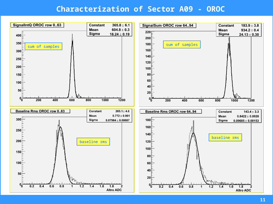
11
sum of samples
Characterization of Sector A09 - OROC
baseline rmsbaseline rms
sum of samples

12
Power Regulators
RCU status and plans …
Readout Control Unit 1/2
DCS CARD
SIU CARD

13
Readout Control Unit 2/2
Mass Production (240 units including 10% spares) completed November ‘05
Mass Test completed December ’05
Delivery of tested DCS cards Mar ‘06
Delivery of tested SIU cards (DAQ project): 1st lot (108 units) Mar ’06 2nd lot (108 units) May ‘06
Assembly and final test of RCU + SIU + DCS: Apr – Jun ‘06
Installation and commissioning of RCUs: May – Aug ‘06
Production, test, installation and commissioning
14
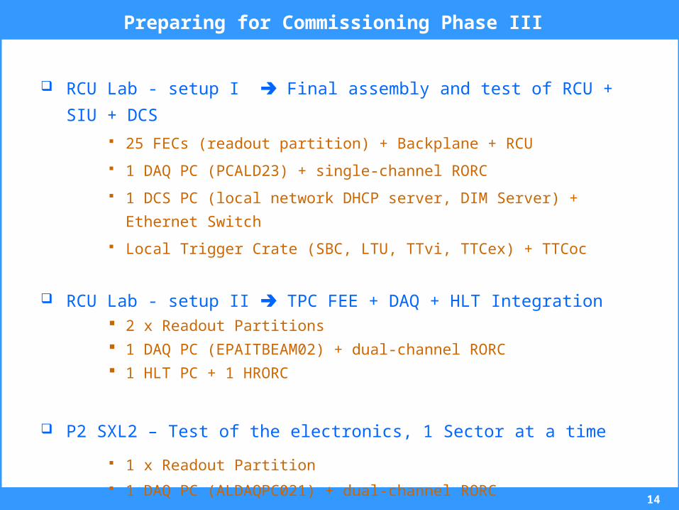
Preparing for Commissioning Phase III
RCU Lab - setup I Final assembly and test of RCU + SIU + DCS
25 FECs (readout partition) + Backplane + RCU
1 DAQ PC (PCALD23) + single-channel RORC
1 DCS PC (local network DHCP server, DIM Server) + Ethernet Switch
Local Trigger Crate (SBC, LTU, TTvi, TTCex) + TTCoc
RCU Lab - setup II TPC FEE + DAQ + HLT Integration 2 x Readout Partitions
1 DAQ PC (EPAITBEAM02) + dual-channel RORC
1 HLT PC + 1 HRORC
P2 SXL2 – Test of the electronics, 1 Sector at a time
1 x Readout Partition
1 DAQ PC (ALDAQPC021) + dual-channel RORC
15
Conclusions
Installation of FECs almost complete (97% done)
The complete electronic chain of one TPC sector has been characterized
gain, baseline and noise distributions well within specifications
Installation of backplanes was completed by Mar ’06
Installation and commissioning of RCUs in May - Aug ‘06