1. Eng-A Novel Approach on Electricity Billing and fault .... Eng-A... · ... PIC 16F877A...
16
Impact Factor(JCC): 1.3268 - This article can be downloaded from www.impactjournals.us IMPACT: International Journal of Research in Engineering & Technology (IMPACT: IJRET) ISSN(E): 2321-8843; ISSN(P): 2347-4599 Vol. 2, Issue 3, Mar 2014, 1-16 © Impact Journals A NOVEL APPROACH ON ELECTRICITY BILLING AND FAULT NOTIFICATION V. SUBRAMANIYAN 1 , A. SRI BAVANI 2 , I. VIKRAMAN 3 , K. SRIMATHI 4 & R. GOWTHAMI 5 1,2,3,4 UG Student, Department of Electrical and Electronics Engineering, Dr. Mahalingam College of Engineering and Technology, Pollachi, Tamil Nadu, India 5 Assistant Professor, Department of Electrical and Electronics Engineering, Dr. Mahalingam College of Engineering and Technology, Pollachi, Tamil Nadu, India ABSTRACT The present systems of energy billing are error prone, time and labor consuming. The Service Provider for energy uses conventional method for calculating the energy consumed by individual consumer. Now-a-days, automation finds importance in every field. So, E-metering (Electronic Metering) has gone through rapid technological advancements and there is increased demand for an efficient and reliable Automatic Meter Reading (AMR) system. This paper presents a fully automated energy meter. To keep pace with increased necessity of advanced metering infrastructure and near real time, a two way data communication technique between the power distribution company (Electricity Board) and the consumer is used. The proposed system uses PIC16F877A microcontroller. A New interactive user friendly GUI is developed using Microsoft visual studio .NET framework and C #. KEYWORDS: GSM, AMR, Visual Studio, PIC 16F877A Microcontroller, Visual Studio .NET, C# INTRODUCTION Electrical power has become indispensable to human survival and progress. The conventional method includes the electro mechanical induction meter operated by counting the revolution of an aluminum disc that is made to rotate at a speed proportional to the power. The number of revolutions is thus proportional to the energy usage. Errors that are related to the existing energy billing system are electro mechanical error and human error. The proposed system is to design a simple low cost wireless GSM based energy meter and its associated web interface for managing the energy meter data. This system automatically reads the energy meter data and sends it to the service provider on reception of a specific message from service provider. The proposed system provides auto disconnect of power supply if the bill is not paid (Out- Standing dues) and auto reconnect of power supply. This novel system also provides the auto announcement feature from consumer side to Electricity Board and vice versa. This system also allows low voltage and power factor lagging announcement features to the Electricity board from consumer place automatically. A Personal Computer with GSM receiver at the server end which contain the database, act as the billing point or server. Live meter reading from the GSM enabled energy meter is sent back to the server periodically and these details are updated in the central database as well as in the non volatile memory in the consumer end. A LCD display in the consumer side displays the voltage, current, power factor, units consumed, total cost for the consumption with an alarm indication. A keypad and RTC is used with non volatile memory to store the date and time.
Transcript of 1. Eng-A Novel Approach on Electricity Billing and fault .... Eng-A... · ... PIC 16F877A...

Impact Factor(JCC): 1.3268 - This article can be downloaded from www.impactjournals.us
IMPACT: International Journal of Research in Engineering & Technology (IMPACT: IJRET) ISSN(E): 2321-8843; ISSN(P): 2347-4599 Vol. 2, Issue 3, Mar 2014, 1-16 © Impact Journals
A NOVEL APPROACH ON ELECTRICITY BILLING AND FAULT N OTIFICATION
V. SUBRAMANIYAN 1, A. SRI BAVANI 2, I. VIKRAMAN 3, K. SRIMATHI 4 & R. GOWTHAMI 5 1,2,3,4UG Student, Department of Electrical and Electronics Engineering, Dr. Mahalingam College of Engineering and
Technology, Pollachi, Tamil Nadu, India 5Assistant Professor, Department of Electrical and Electronics Engineering, Dr. Mahalingam College of Engineering and
Technology, Pollachi, Tamil Nadu, India
ABSTRACT
The present systems of energy billing are error prone, time and labor consuming. The Service Provider for energy
uses conventional method for calculating the energy consumed by individual consumer. Now-a-days, automation finds
importance in every field. So, E-metering (Electronic Metering) has gone through rapid technological advancements and
there is increased demand for an efficient and reliable Automatic Meter Reading (AMR) system. This paper presents a
fully automated energy meter. To keep pace with increased necessity of advanced metering infrastructure and near real
time, a two way data communication technique between the power distribution company (Electricity Board) and the
consumer is used. The proposed system uses PIC16F877A microcontroller. A New interactive user friendly GUI is
developed using Microsoft visual studio .NET framework and C #.
KEYWORDS: GSM, AMR, Visual Studio, PIC 16F877A Microcontroller, Visual Studio .NET, C#
INTRODUCTION
Electrical power has become indispensable to human survival and progress. The conventional method includes the
electro mechanical induction meter operated by counting the revolution of an aluminum disc that is made to rotate at a
speed proportional to the power. The number of revolutions is thus proportional to the energy usage. Errors that are related
to the existing energy billing system are electro mechanical error and human error.
The proposed system is to design a simple low cost wireless GSM based energy meter and its associated web
interface for managing the energy meter data. This system automatically reads the energy meter data and sends it to the
service provider on reception of a specific message from service provider. The proposed system provides auto disconnect
of power supply if the bill is not paid (Out- Standing dues) and auto reconnect of power supply. This novel system also
provides the auto announcement feature from consumer side to Electricity Board and vice versa. This system also allows
low voltage and power factor lagging announcement features to the Electricity board from consumer place automatically.
A Personal Computer with GSM receiver at the server end which contain the database, act as the billing point or
server. Live meter reading from the GSM enabled energy meter is sent back to the server periodically and these details are
updated in the central database as well as in the non volatile memory in the consumer end. A LCD display in the consumer
side displays the voltage, current, power factor, units consumed, total cost for the consumption with an alarm indication.
A keypad and RTC is used with non volatile memory to store the date and time.

2 V. Subramaniyan, A. Sri Bavani, I. Vikraman, K. Srimathi & R. Gowthami
Index Copernicus Value: 3.0 - Articles can be sent to [email protected]
Energy Conservation and its Need
Energy conservation is crucial for the economical way of power generation. Energy conservation does not mean
curtailment in energy use at the expense of industrial and economic growth; rather it means effective utilization of energy
resources ensuring the same level of economic and industrial activity with lesser inputs of energy. Despite the fact there
has been a phenomenal increase in energy production in the past four decades, energy shortage continued to exist.
This is mainly because of increasing demand, limited resources, rapid depletion and increasing cost of harnessing the
resources. Hence it becomes imperative to attribute a special status to energy conservation in the world.
LITERATURE REVIEW
For this work existing energy meter reading techniques in India are analyzed and conducted an extensive study on
different energy measuring instruments available now.
Existing System
The methods of illegal usage of electricity uses the electro mechanical objects, a fixed magnet, the external phase
before meter terminals and switching the energy cables at the meter connector box. The problem identified in existing
system is as follows: The Electricity Board employee is going to each and every house and notes the reading and generates
the bill. It will take a lot of time and laborious task. If the consumers do not pay the bill one of the Electricity board
employees should go to the consumer place and disconnect the supply. After few days the bill status of the corresponding
consumer is checked again and if the bill paid, one of the Electricity Board employee should go to the consumer place and
reconnect the supply. The manual operator cannot find the un-authorized connections or mal practices carried out by the
consumer to reduce or stop the meter reading/power supply. The human error can open an opportunity for corruption done
by the human meter reader. So the problem which arises in the billing system can become inaccurate and inefficient.
Proposed System
Our Proposed system is to make the energy meter as a smart meter to read the energy consumed, voltage level and
power factor and also auto announcement features such as power failure, power factor lagging and low voltage level.
In this system a relay circuit is used to disconnect the supply to the consumer for large outstanding dues. This system
minimizes the power and time wastage. Electrically Erasable Programmable Read Only memory (EEPROM) is used to
store the data regularly. By using Real Time Clock (RTC) the real time date and time is maintained in off line position.
A keypad is used to view and erase the EEPROM. The monthly usage is also sent to the consumer through Short
Messaging Service (SMS) and also displayed in LCD display. The announcement feature and disconnect/reconnect
features are controlled by the visual basic codes. The microcontroller receives the command from server and act.
The advantage of this system is to reduce the effort of human beings. Another advantage is this system can be used in
remote area or small villages.
Table 1: Shows the Technical Specification of GSM Based Energy Meter
Sr. No Parameter Specification 1. Operating Voltage 240V 2. Operating Frequency 50Hz 3. Pulses 3200Imp/Kwh 4. GSM Modem TriBand GSM Modem(GSM 300/900 MHz) designed for data SMS

A Novel Approach on Electricity Billing and Fault Notification 3
Impact Factor(JCC): 1.3268 - This article can be downloaded from www.impactjournals.us
Table 1: Contd., 5. Automatic Reading Feature It can be remote monitoring and controlling anywhere
6. Auto Disconnect feature It provide remote shut off facility to the consumer that have large outstanding dues
7. Auto Reconnect feature It can be reconnect the power supply after pay outstanding dues
8. Power failure alert This system provide power cut information to the consumer from EB and vice versa
9. Memory Non volatile based energy reading system
10. Display System LCD display system used for energy display, voltage, current, frequency, power factor
11. Total load calculation This system gives information of total load used in particular house at any time to energy provider through SMS
CIRCUIT SOLUTION
System Architecture
Figure 1: Block Diagram
The Consumer end consists of the power supply unit, the microcontroller, the GSM Modem, LCD Display,
Voltage measurement unit, current measurement unit, power factor measurement unit, Digital energy meter, Keypad, RTC,
a relay unit and a buzzer (Alarm).
The Server end consists of a Personal Computer and a GSM Modem interfaced with PC through RS232.
The Personal Computer acts as a server which contains the consumer database.
Figure 1 shows the block diagram of proposed system. AMR Continuously monitor and record the energy meter.
This can be achieved by using microcontroller. The GSM modem is interfaced with personal computer. Microcontroller
unit continuously monitor the energy meter pulses and display on LCD. This gives the information of power consumption
in a house. For the information of power cut microcontroller unit is interface with RTC clock and relay.
For communication microcontroller unit is also interfaced with GSM modem by using MAX 232 protocol.

4 V. Subramaniyan, A. Sri Bavani, I. Vikraman, K. Srimathi & R. Gowthami
Index Copernicus Value: 3.0 - Articles can be sent to [email protected]
Circuit Architecture
Figure 2: Consumer End
Figure 3: Server End
The shown in figure 2 & figure 3 shows the circuit diagram of Consumer end and Server end respectively.
The transmitter and the receiver pin of the GSM is connected to the receiver and transmitter pin of the microcontroller that
will be used to have transmission of control messages between the two. The programming is made as so that it counts the
number of pulses that is detected by the Energy Meter and stores the count in the controller.
The LCD is used to display the count and the impulse of the energy meter. It is connected to port 0 and port 1 of
the microcontroller. The register, read and write is connected to the port 1 and controls the reading and writing in the LCD.
The power supply to the system is provided using a 12V/750mA transformer and is bridge rectified and finally reduced to
5V using a voltage regulator.

A Novel Approach on Electricity Billing and Fault Notification 5
Impact Factor(JCC): 1.3268 - This article can be downloaded from www.impactjournals.us
Flow Diagram of this System
Figure 4: Consumer End
Figure 4 shows that energy meter continuously display the Pulse and unit according power consumption.
When Energy provider company requires data for calculation of bill so the consumer send a message to EB.
It also provides the facility of power disconnect to customer who have large outstanding dues by sending a code to the
energy meter. Microcontroller has a program of matching of this code to power disconnect code. If this code matches then
power disconnect to respective meter. It also provides a facility of power re-connect if the outstanding bill amount is paid
by sending a code to the energy meter. Microcontroller has a program of matching of this code power re-connect code.
If this code is matches then power is reconnected to respective meter. Power failure feature is performed using interrupt
signal. The auto announcement feature for low voltage and power factor lagging is also provided in this system by using a
microcontroller.
Figure 5: Server End
Figure 5 shows the working of a server. The auto announcement feature for Power shutdown details is also
provided in this system by using a Personal Computer which acts as a server interfaced with GSM modem.

6 V. Subramaniyan, A. Sri Bavani, I. Vikraman, K. Srimathi & R. Gowthami
Index Copernicus Value: 3.0 - Articles can be sent to [email protected]
DETAILED DESIGN
Hardware Detailed Design
Power Supply
The microcontroller and other devices get power supply from AC to DC adapter or from direct ac lines through
voltage regulator. The ac voltage, typically 220V rms, is connected to a transformer, which steps that ac voltage down to
the level of the desired dc output. A diode rectifier then provides a full-wave rectified voltage that is initially filtered by a
simple capacitor filter to produce a dc voltage. This resulting dc voltage usually has some ripple or ac voltage variation.
A regulator circuit removes the ripples and also remains the same dc value even if the input dc voltage varies, or the load
connected to the output dc voltage changes. This voltage regulation is usually obtained using one of the popular voltage
regulator IC units. The series 78 regulators provide fixed positive regulated voltages from 5 to 24 volts. Similarly, the
series 79 regulators provide fixed negative regulated voltages from 5 to 24 volts.
For ICs, microcontroller, LCD Consumes 5 volts
For alarm circuit, op-amp, relay circuits Consumes 12 volts
Figure 6
Voltage Measurement
The circuit shown in figure 7 is designed to monitor the supply voltage. The supply voltage that has to be
monitored is step down by the potential transformer whose range is 0-6Volts The step down voltage is rectified by the
precision rectifier. The precision rectifier is a configuration obtained with an operational amplifier in order to have a circuit
behaving like an ideal diode or rectifier.
Figure 7: Voltage Measurement

A Novel Approach on Electricity Billing and Fault Notification 7
Impact Factor(JCC): 1.3268 - This article can be downloaded from www.impactjournals.us
Current Measurement
The circuit shown in figure 8 is designed to monitor the supply current. The supply current that has to be
monitored is step down by the current transformer. The step down current is converted by the voltage with the help of
shunt resistor. Then the converted voltage is rectified by the precision rectifier. The precision rectifier is a configuration
obtained with an operational amplifier in order to have a circuit behaving like an ideal diode or rectifier.
Figure 8: Current Measurement
Power Factor Measurement
The circuit shown in figure 9 is designed to find the power factor in the power line. The power line voltage and
current is monitored through the potential and current transformer respectively.
The potential transformer is used to step down the mains supply voltage to low voltage level. The voltage level is
from 440V AC to 6V AC. Then the output of the transformer is given to Zero Crossing Detector. The current consumed by
the load is measured with the help of a current transformer. The current transformer will convert the load current into lower
values of current output that will be converted in to voltage with the help of the shunt resistor. Then the corresponding
AC voltage is given to zero crossing detector. The Zero Crossing Detector is used to convert the sine wave to square wave
signal. The zero crossing detectors are constructed by the operational amplifier LM 741. The inverting and non inverting
input terminals are connected to the potential transformer and current transformer terminals respectively. So the input sine
wave signal is converted in to square wave signals. The square signal is in the range of +12v to -12v level. Then the square
wave signal is given to base of the BC 547 switching transistor in order to convert the TTL voltage 0 to 5v level. Then the
both ZCD’s outputs are given to logical XOR gate 74LS86 to find the phase angle difference between the voltage and
current. The XOR gate output is given to microcontroller or PC and calculates the power factor with help of software.
Figure 9: Power Factor Measurement

8 V. Subramaniyan, A. Sri Bavani, I. Vikraman, K. Srimathi & R. Gowthami
Index Copernicus Value: 3.0 - Articles can be sent to [email protected]
Digital Energy Meter
The circuit shown in figure 10 is designed to measure the energy consumption through Digital energy meter.
The output from digital energy meter is given to the 4N35 opto coupler as IC input. The opto coupler acts as an isolation
circuit. The AC Line Digital logic is olator, is used in AC line detection over short circuit prevention. 4N35 (short) consists
of a gallium arsenide infrared emitting diode coupled with a silicon phototransistor in a dual in−line package. In that
IC output will be always low. When input from energy meter comes, IC gives logic high as output. If this IC output is low
means the output of BC547 is High, so the LED behind that operation is in Off condition also the input given to controller
also low. When the output of 4N37 is high means the output of BC547 is Low, so the LED behind that operation is in
ON condition also the input given to controller also high. Like this whenever the input comes from digital energy meter,
the LED on board will glow, also the input to controller changes their logic from high to low. Otherwise the output of
circuit remains high condition. The output logic is inverted through 74LS04 which is placed on the circuit at final point.
So the unit of consumption is measured through the changes in IC logic.
Figure 10: Digital Energy Meter
PIC 16F877A Microcontroller
The microcontroller used in the proposed system is PIC 16F877A. PIC microcontroller is the first RISC based
microcontroller fabricated in CMOS (complementary metal oxide semiconductor) that uses separate bus for instruction and
data allowing simultaneous access of program and data memory. The main advantage of CMOS and RISC combination is
low power consumption resulting in a very small chip size with a small pin count. The main advantage of CMOS is that it
has immunity to noise than other fabrication techniques. Various microcontrollers offer different kinds of memories.
EEPROM, EPROM, FLASH etc. are some of the memories of which FLASH is the most recently developed. Technology
that is used in PIC16F877 is flash technology, so that data is retained even when the power is switched off.
Easy programming and erasing are other features of PIC 16F877A.
Figure 11: PIC Microcontroller

A Novel Approach on Electricity Billing and Fault Notification 9
Impact Factor(JCC): 1.3268 - This article can be downloaded from www.impactjournals.us
Relay Circuit
Relay is used to shutting off the electric power supply when the consumer has large outstanding dues. Whenever
the consumer clears the outstanding dues the power supply is resumed by relay module. The circuit shown in figure 12 is
designed to control the load. The load may be motor or any other load. The load is turned ON and OFF through relay.
The relay ON and OFF is controlled by the pair of switching transistors (BC 547). The relay is connected in the Q2
transistor collector terminal. A Relay is an electromagnetic switching device which consists of three pins. They are
Common, Normally close (NC) and normally open (NO).
The relay common pin is connected to supply voltage. The normally open (NO) pin is connected to load.
When high pulse signal is given to base of the Q1 transistor, the transistor starts conducting and shorts the collector and
emitter terminal and zero signals is given to base of the Q2 transistor. So the relay is turned OFF state.
When low pulse is given to base of transistor Q1 transistor, the transistor is turned OFF. When 12V is given to the
base of transistor Q2, it starts conducting and makes the relay ON. When the common and NO terminal of the relay are
shorted, load gets the supply voltage through relay.
Figure 12: Relay Circuit
LCD Display
Liquid Crystal Display is used to display the voltage, current, power factor, frequency and the number of units
consumed by the consumer. Here we have used 20X4 alphanumeric LCD display which has 250KHz clock frequency.
The meaning for 20X4 is Number of columns is 20 and the number of rows is 4. The LCD display is interfaced with the
PIC microcontroller to display all the details. The LCD’s are light weight with a few mm thickness. Since the LCD
consumes less power, they can be compatible with low power electronic circuits and can be powered for long duration.
Alarm Circuit
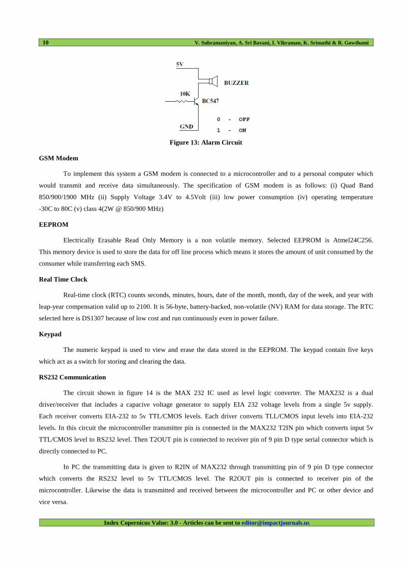
The circuit shown in figure 13 is designed to control the buzzer. The buzzer ON and OFF is controlled by the pair
of switching transistors (BC 547). The buzzer is connected to the Q2 transistor collector terminal. When high pulse signal
is given to base of the Q1 transistor, it starts conducting and close the collector and emitter terminal where zero signals is
given to base of the Q2 transistor. Hence Q2 transistor and buzzer is turned OFF state. When low pulse is given to base of
transistor Q1, the transistor is turned OFF. when 12v is given to base of Q2 transistor. The transistor conducts and at the
same time buzzer is energized and produces the sound signal.
10 V. Subramaniyan, A. Sri Bavani, I. Vikraman, K. Srimathi & R. Gowthami
Index Copernicus Value: 3.0 - Articles can be sent to [email protected]
Figure 13: Alarm Circuit
GSM Modem
To implement this system a GSM modem is connected to a microcontroller and to a personal computer which
would transmit and receive data simultaneously. The specification of GSM modem is as follows: (i) Quad Band
850/900/1900 MHz (ii) Supply Voltage 3.4V to 4.5Volt (iii) low power consumption (iv) operating temperature
-30C to 80C (v) class 4(2W @ 850/900 MHz)
EEPROM
Electrically Erasable Read Only Memory is a non volatile memory. Selected EEPROM is Atmel24C256.
This memory device is used to store the data for off line process which means it stores the amount of unit consumed by the
consumer while transferring each SMS.
Real Time Clock
Real-time clock (RTC) counts seconds, minutes, hours, date of the month, month, day of the week, and year with
leap-year compensation valid up to 2100. It is 56-byte, battery-backed, non-volatile (NV) RAM for data storage. The RTC
selected here is DS1307 because of low cost and run continuously even in power failure.
Keypad
The numeric keypad is used to view and erase the data stored in the EEPROM. The keypad contain five keys
which act as a switch for storing and clearing the data.
RS232 Communication
The circuit shown in figure 14 is the MAX 232 IC used as level logic converter. The MAX232 is a dual
driver/receiver that includes a capacive voltage generator to supply EIA 232 voltage levels from a single 5v supply.
Each receiver converts EIA-232 to 5v TTL/CMOS levels. Each driver converts TLL/CMOS input levels into EIA-232
levels. In this circuit the microcontroller transmitter pin is connected in the MAX232 T2IN pin which converts input 5v
TTL/CMOS level to RS232 level. Then T2OUT pin is connected to receiver pin of 9 pin D type serial connector which is
directly connected to PC.
In PC the transmitting data is given to R2IN of MAX232 through transmitting pin of 9 pin D type connector
which converts the RS232 level to 5v TTL/CMOS level. The R2OUT pin is connected to receiver pin of the
microcontroller. Likewise the data is transmitted and received between the microcontroller and PC or other device and
vice versa.

A Novel Approach on Electricity Billing and Fault Notification 11
Impact Factor(JCC): 1.3268 - This article can be downloaded from www.impactjournals.us
Figure 14: RS232 Communication
Software Detailed Design
MPLAB
MPLAB IDE is an integrated development environment that provides development engineers with the flexibility
to develop and debug the firmware for various Microchip devices. MPLAB IDE is a windows-based Integrated
Development Environment for the Microchip Technology incorporated with PIC microcontroller (MCU) and ds PIC digital
signal controller (DSC) families. In the MPLAB IDE, you can:
• Create source code using the built-in editor.
• Assemble, compile and link source code using various language tools. C compilers are available from Microchip
and other third party vendors.
• Debug the executable logic by watching program flow with a simulator, such as MPLAB SIM, or in real time with
an emulator, such as MPLAB ICE. Third party emulators that work with MPLAB IDE are also available.
• Make timing measurements.
• View variables in watch windows.
• Program firmware into devices with programmers such as PICSTART Plus or PRO MATE II.
• Find quick answers to questions from the MPLAB IDE on-line Help.
MPLAB Simulator
MPLAB SIM is a discrete-event simulator for the PIC microcontroller (MCU) families. It is integrated into
MPLAB IDE integrated development environment. The MPLAB SIM debugging tool is designed to model the operation
of Microchip Technology's PIC microcontrollers to assist the users in debugging software for these devices
IC PROG
The PRO MATE II is a Microchip microcontroller device programmer. Through interchangeable programming
socket modules, PRO MATE II enables in programming the entire line of microchip PIC microcontroller devices quickly
and easily and many of the Microchip memory parts. PRO MATE II may be used with MPLAB IDE running under
supported Windows OS's, with the command-line controller PROCMD or as a stand-alone programmer.

12 V. Subramaniyan, A. Sri Bavani, I. Vikraman, K. Srimathi & R. Gowthami
Index Copernicus Value: 3.0 - Articles can be sent to [email protected]
Compiler-High Tech C
A program written in the high level language called C; which will be converted into PIC micro MCU machine
code by a compiler. Machine code is suitable for use by a PIC micro MCU or Microchip development system product like
MPLAB IDE.
PIC Start Plus Programmer
The PIC start plus development system from microchip technology provides the product development engineer
with a highly flexible low cost microcontroller design tool set for all microchip PIC micro devices. The PIC start plus
development system includes PIC start plus development programmer and MPLAB IDE. The PIC start plus programmer
gives the product developer ability to program user software in to any of the supported microcontrollers. The PIC start plus
software running under MPLAB provides for full interactive control over the programmer.
Proteus 8 Professional
This is a type of electrical software which is used to simulate the whole project in animated views.
Visual Basic
Visual Basic is a third-generation event-driven programming language and integrated development environment
(IDE) from Microsoft for its COM programming model. Visual Basic .NET (VB.NET) is an object-oriented computer
programming language that can be viewed as an evolution of the classic Visual Basic (VB), implemented on the
.NET Framework. The creation of open-source tools for VB.NET development has been slow compared to C#, although
the Mono development platform provides an implementation of VB.NET-specific libraries and a VB.NET 8.0 compatible
compiler written in VB.NET,[17] as well as standard framework libraries such as Windows Forms GUI library.
Sharp Develop and Mono Develop are open-source alternative IDEs. The usage of visual basic in this system is to act as a
server for billing details and technical notifications.
RESULTS
The Simulation result of our proposed system is as follows:
Figure 15: Simulation Diagram
Figure 15 shows the overall simulation diagram of our proposed system.
A Novel Approach on Electricity Billing and Fault Notification 13
Impact Factor(JCC): 1.3268 - This article can be downloaded from www.impactjournals.us
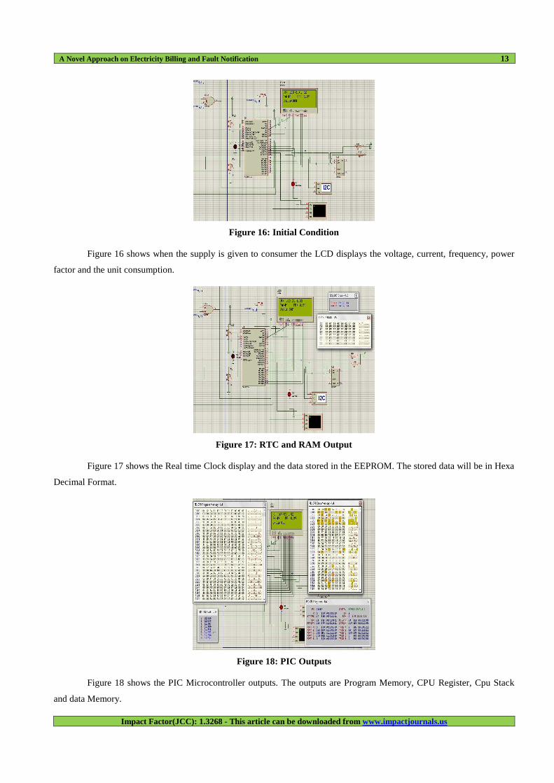
Figure 16: Initial Condition
Figure 16 shows when the supply is given to consumer the LCD displays the voltage, current, frequency, power
factor and the unit consumption.
Figure 17: RTC and RAM Output
Figure 17 shows the Real time Clock display and the data stored in the EEPROM. The stored data will be in Hexa
Decimal Format.
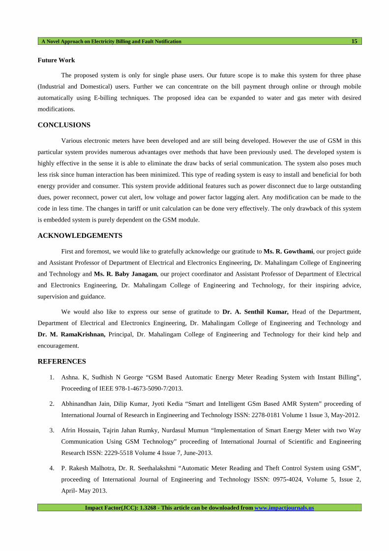
Figure 18: PIC Outputs
Figure 18 shows the PIC Microcontroller outputs. The outputs are Program Memory, CPU Register, Cpu Stack
and data Memory.

14 V. Subramaniyan, A. Sri Bavani, I. Vikraman, K. Srimathi & R. Gowthami
Index Copernicus Value: 3.0 - Articles can be sent to [email protected]
Figure 19: Normal Voltage Indication
Figure 19 shows that the message is sent to the Electricity Board from the consumer to indicate the supply voltage
is in normal condition.
Figure 20: Unit Message
Figure 20 shows that the Electricity Board Sends the unit consumed to the Consumer Using Short Service
Message format. If the Consumer have large outstanding dues the Supply will disconnect using Relay
(LED will glow OFF).
Figure 21: Low Voltage Indication
Figure 21 shows that the message is sent to the Electricity Board from the consumer to indicate the supply voltage
is in low condition.
A Novel Approach on Electricity Billing and Fault Notification 15
Impact Factor(JCC): 1.3268 - This article can be downloaded from www.impactjournals.us
Future Work
The proposed system is only for single phase users. Our future scope is to make this system for three phase
(Industrial and Domestical) users. Further we can concentrate on the bill payment through online or through mobile
automatically using E-billing techniques. The proposed idea can be expanded to water and gas meter with desired
modifications.
CONCLUSIONS
Various electronic meters have been developed and are still being developed. However the use of GSM in this
particular system provides numerous advantages over methods that have been previously used. The developed system is
highly effective in the sense it is able to eliminate the draw backs of serial communication. The system also poses much
less risk since human interaction has been minimized. This type of reading system is easy to install and beneficial for both
energy provider and consumer. This system provide additional features such as power disconnect due to large outstanding
dues, power reconnect, power cut alert, low voltage and power factor lagging alert. Any modification can be made to the
code in less time. The changes in tariff or unit calculation can be done very effectively. The only drawback of this system
is embedded system is purely dependent on the GSM module.
ACKNOWLEDGEMENTS
First and foremost, we would like to gratefully acknowledge our gratitude to Ms. R. Gowthami, our project guide
and Assistant Professor of Department of Electrical and Electronics Engineering, Dr. Mahalingam College of Engineering
and Technology and Ms. R. Baby Janagam, our project coordinator and Assistant Professor of Department of Electrical
and Electronics Engineering, Dr. Mahalingam College of Engineering and Technology, for their inspiring advice,
supervision and guidance.
We would also like to express our sense of gratitude to Dr. A. Senthil Kumar , Head of the Department,
Department of Electrical and Electronics Engineering, Dr. Mahalingam College of Engineering and Technology and
Dr. M. RamaKrishnan, Principal, Dr. Mahalingam College of Engineering and Technology for their kind help and
encouragement.
REFERENCES
1. Ashna. K, Sudhish N George “GSM Based Automatic Energy Meter Reading System with Instant Billing”,
Proceeding of IEEE 978-1-4673-5090-7/2013.
2. Abhinandhan Jain, Dilip Kumar, Jyoti Kedia “Smart and Intelligent GSm Based AMR System” proceeding of
International Journal of Research in Engineering and Technology ISSN: 2278-0181 Volume 1 Issue 3, May-2012.
3. Afrin Hossain, Tajrin Jahan Rumky, Nurdasul Mumun “Implementation of Smart Energy Meter with two Way
Communication Using GSM Technology” proceeding of International Journal of Scientific and Engineering
Research ISSN: 2229-5518 Volume 4 Issue 7, June-2013.
4. P. Rakesh Malhotra, Dr. R. Seethalakshmi “Automatic Meter Reading and Theft Control System using GSM”,
proceeding of International Journal of Engineering and Technology ISSN: 0975-4024, Volume 5, Issue 2,
April- May 2013.

16 V. Subramaniyan, A. Sri Bavani, I. Vikraman, K. Srimathi & R. Gowthami
Index Copernicus Value: 3.0 - Articles can be sent to [email protected]
5. S. Sukhumar, P. Mukesh Aravind, L. Manivannan, P. Naveen Kumar and N. Suthathira Rathina “GSM Based
Automatic Trip Control System for energy management System” proceeding of International Journal of
Innovative Research in Science, Engineering and Technology ISSN: 2319-8753 Volume 2, Issue 12,
December 2013.
6. Abhinandhan Jain, Dilip Kumar, Jyoti Kedia “Design and Development of GSm Based Energy Meter” proceeding
of International Journal of Computer Applications(0975-888) Volume 47, Issue 12, June 2012.
7. T. Kamalesh, M. Veda Chary “Post-Paid Wireless Meter Reading System for Automatic Power Controlling and
Consumption Billing Appliances” proceeding of International Journal of Scientific Engineering and Technology
Research Volume 2 Issue 9, September 2013.
8. Bharat Kulkarni “GSm Based AMR System using ARM Controller” proceeding of International Journal of
Emerging Technology and Advanced Engineering ISSN: 2250-2459 Volume 2 Issue 5 May-2012.
9. Tanvira Ismail, Partha Protim Dutta, Bikash Borgohain, Dipannita Das, Amit Prasad “Electricity Meter Reading
Using GSM”: proceeding of International Journal of Computer & Electronics Research Volume 2 Issue 3
June 2013.
10. Rahul Ganesh Sarangle, Dr.Uday Pandit Khot, Jayen Modi “GSM Based Power Meter Reading and Control
System” Proceeding of International Journal of Engineering Research and Applications ISSN: 2248-9622
Volume 2 Issue 4 June July 2012.
AUTHOR’S DETAILS
V. Subramaniyan, is pursuing, final year Bachelor of Engineering in the discipline of Electrical & Electronics
Engineering at Dr. Mahalingam College of Engineering and Technology, Pollachi, under Anna University, Chennai, India.
A. SriBavani, is pursuing, final year Bachelor of Engineering in the discipline of Electrical & Electronics
Engineering at Dr. Mahalingam College of Engineering and Technology, Pollachi, under Anna University, Chennai, India.
I. Vikraman, is pursuing, final year Bachelor of Engineering in the discipline of Electrical & Electronics
Engineering at Dr. Mahalingam College of Engineering and Technology, Pollachi, under Anna University, Chennai, India
K. Srimathi, is pursuing, final year Bachelor of Engineering in the discipline of Electrical & Electronics
Engineering at Dr. Mahalingam College of Engineering and Technology, Pollachi, under Anna University, Chennai, India.
R. Gowthami, is currently working as an Assistant Professor in the Department of Electrical & Electronics
Engineering at Dr. Mahalingam College of Engineering and Technology, Pollachi, India.