1 Distributed and Coordinated Spectrum Access …zaheer/bonding.pdf · Distributed and Coordinated...
30
1 Distributed and Coordinated Spectrum Access Methods for Heterogeneous Channel Bonding Zaheer Khan, Janne Lehtomäki, Simon Scott, Zhu Han, Marwan Krunz, and Alan Marshall Abstract Channel bonding (CB) is a technique that enables a wireless link to combine channels and achieve higher data rates. In this paper, competition for efficient spectrum access among autonomous users with heterogeneous CB capabilities is considered. Specifically, we propose distributed and coordinated channel/bonding selection methods under signal-to-interference-plus-noise ratio (SINR) and collision- protocol models. In our methods, users utilize only limited feedback to distributively arrive at CB selections that minimize their probability of conflict. The proposed method utilizes a novel channel quality metric, which is based on the ratio of noise power to the sum of interference and noise power. It is shown that CB can lead to higher data rates, and it is most beneficial when users have a high SINR. However, it is also shown that as the ratio of users to available channels increases, CB performance degrades. Our results show that under certain scenarios, the proposed coordinated and distributed channel/bonding selection schemes help users converge fast to conflict-free channel selections as compared to the other channel/bonding selection schemes. Moreover, the proposed schemes result in considerably superior performance to existing CB schemes in terms of network data rate. Index Terms Channel bonding, distributed users, heterogeneous capabilities, collision-protocol model, SINR- protocol model, spectrum access system, opportunistic spectrum access. I. I NTRODUCTION The use of carrier aggregation (CA) in licensed cellular bands and channel bonding (CB) in unlicensed bands has been shown to increase network performance under certain conditions [1]–[3]. In CA, multiple contiguous and/or non-contiguous subcarriers are utilized for parallel data transmission to or from the same user. Wireless systems such as WiFi networks rely on Z. Khan is with the University of Liverpool, UK, and part of this work was done while he was working at the University of Oulu, Finland, J. Lehtomäki and S. Scott are with the University of Oulu, Finland, Z. Han is with the University of Houston, USA, M. Krunz is with the University of Arizona, USA, and A. Marshall is with the University of Liverpool, UK.
Transcript of 1 Distributed and Coordinated Spectrum Access …zaheer/bonding.pdf · Distributed and Coordinated...
1
Distributed and Coordinated Spectrum Access
Methods for Heterogeneous Channel Bonding
Zaheer Khan, Janne Lehtomäki, Simon Scott, Zhu Han, Marwan Krunz, and
Alan Marshall
Abstract
Channel bonding (CB) is a technique that enables a wireless link to combine channels and achieve
higher data rates. In this paper, competition for efficient spectrum access among autonomous users
with heterogeneous CB capabilities is considered. Specifically, we propose distributed and coordinated
channel/bonding selection methods under signal-to-interference-plus-noise ratio (SINR) and collision-
protocol models. In our methods, users utilize only limitedfeedback to distributively arrive at CB
selections that minimize their probability of conflict. Theproposed method utilizes a novelchannel
quality metric, which is based on the ratio of noise power to the sum of interference and noise
power. It is shown that CB can lead to higher data rates, and itis most beneficial when users have
a high SINR. However, it is also shown that as the ratio of users to available channels increases,
CB performance degrades. Our results show that under certain scenarios, the proposed coordinated and
distributed channel/bonding selection schemes help usersconverge fast to conflict-free channel selections
as compared to the other channel/bonding selection schemes. Moreover, the proposed schemes result in
considerably superior performance to existing CB schemes in terms of network data rate.
Index Terms
Channel bonding, distributed users, heterogeneous capabilities, collision-protocol model, SINR-
protocol model, spectrum access system, opportunistic spectrum access.
I. INTRODUCTION
The use of carrier aggregation (CA) in licensed cellular bands and channel bonding (CB)
in unlicensed bands has been shown to increase network performance under certain conditions
[1]–[3]. In CA, multiple contiguous and/or non-contiguoussubcarriers are utilized for parallel
data transmission to or from the same user. Wireless systemssuch as WiFi networks rely on
Z. Khan is with the University of Liverpool, UK, and part of this work was done while he was working at the University ofOulu, Finland, J. Lehtomäki and S. Scott are with the University of Oulu, Finland, Z. Han is with the University of Houston,USA, M. Krunz is with the University of Arizona, USA, and A. Marshall is with the University of Liverpool, UK.
2
CB techniques to combine multiple adjacent channels to formlarger channels. Recent advances
in spectrum aggregation technologies allow the cellular industry to extend CA/CB techniques
to heterogeneous shared-spectrum bands, such as unlicensed spectrum in 2.4 and 5 GHz bands,
and opportunistic spectrum access (OSA) bands [4]–[6].
In this paper, we consider CB scenarios for distributed cognitive radio networks where sec-
ondary users compete for opportunistic access in potentially available primary user (PU) channels.
Techniques designed for conventional channel aggregationin the licensed bands, such as CA
techniques in LTE-A networks [7], cannot be directly applied to perform CA/CB in unlicensed
and OSA bands. Unlike the licensed bands, unlicensed and OSAbands exhibit high unpre-
dictability in the interference environment due to uncoordinated competing users. Different users
may have different CA/CB capabilities, and this heterogeneity needs to be taken into account
while making CA/CB decisions. Moreover, recent works have shown that when multiple users
with heterogeneous CB capabilities independently employ CB in unlicensed or OSA bands, the
performance may actually degrade due to adjacent channel interference (ACI) [3].
In this paper, we design distributed and coordinated CB methods under both signal-to-interference-
plus-noise ratio (SINR) and collision-protocol models. Under the SINR-protocol model, when
two or more simultaneous transmissions occur on the same channel, additional interference will
be experienced at the respective receivers, and loss of communication occurs when the sum
of interference exceeds a certain threshold [8]. In the collision-protocol model, all users are in
the same collision domain, and if two or more of these users transmit simultaneously on the
same channel, a collision occurs and the data frame is assumed to be lost. In practice, the SINR
at each receiver is a function of the transmission powers of interfering users, and the channel
characteristics, such as path loss and fading. This makes the design problem of autonomous OSA
schemes under the SINR model fundamentally different from and the analysis considerably more
complex than the same problem under the collision-protocolmodel.
We particularly focus on CB-based spectrum access techniques for scenarios where users
operate over wide swathes of spectrum and use a single-radiotransceiver to combine multiple
channels. We consider two possible bonding models: (1) users can combine only adjacent
channels to use them as a single pipe, as in some WLANs [3]; and(2) users can combine
both adjacent and non-adjacent channels to use them as a single pipe. Note that from a hardware
standpoint, it is beneficial for autonomous users to bond multiple channels and use them as a
single pipe for data transmission since this approach requires only one RF unit. This is different
from some non-contiguous CA techniques that require multiple RF units for operating over
3
aggregated non-adjacent frequency channels [9].
One special yet practically significant scenario for the underlying problem is CB for downlink
transmissions by small cell base stations/access points. These base stations/access points can be
deployed by multiple, independent wireless operators for data offloading purposes. Although we
consider opportunistic use scenarios, our proposed CB methods can be easily adapted to other
spectrum sharing scenarios; for example, in scenarios where multiple users have equal rights to
access the spectrum.
The main contributions and findings of this paper are as follows:
• We study the problem of spectrum access among autonomous users with heterogeneous CB
capabilities, under both the SINR and collision-protocol models. We propose a distributed
CB method and also a coordinated CB method that allow wireless links to arrive at CB
selections that minimize the likelihood of interference between users.
• Under the SINR-protocol model, a CB selection method calledπAut, where ‘Aut’ denotes
autonomous, is proposed for scenarios where autonomous users (with heterogeneous CB
capabilities) searching for spectrum opportunities can only utilize their own limited feed-
back information to arrive at CB selections that minimize the probability of conflict. By
limited feedback information, we mean information about a successful transmission, loss
of communication, or no transmission. The key idea behind the proposedπAut is that an
autonomous user is either in a ‘persist’ state, in which it will select the same CB selection
with a certain probability that is a function of the channel quality, or in an ‘explore’ state,
where it will explore a new CB selection.
• We compare the performance ofπAut to a coordinated distributed method calledπSig, where
‘Sig’ denotes a signal.πSig utilizes simple binary feedback from a spectrum access system
(SAS) [10] to arrive at CB allocations that reduce the likelihood of conflict among users.
Moreover, to provide a benchmark for the performance of the proposed methods, we also
compare them against a centralized CB selection method.
• To evaluate the proposed methods, we consider the followingmetrics: (1) convergence time
to conflict-free CB selections; (2) blocking rate, defined asthe ratio of users who are unable
to communicate successfully to the total number of users; and (3) data rate of all users. We
show that in some scenarios, such as under low user density, the πSig method converges
faster to conflict-free CB selections and enjoys a lower blocking rate compared to the fully
distributedπAut method. However,πAut always outperforms theπSig method in terms of data
rate, and also in terms of blocking rate when user density is high. Our empirical results

4
show that for all the proposed methods, the expected number of rounds to converge to CB
selections that reduce conflict is no more thanO2maxI , whereOmax represents the maximum
CB capability of a user (due to its hardware limitations), and I is the number of users.
• We find that CB achieves higher data rates, and is most beneficial when users have a high
SINR. However, we also find that when the ratio of users to available channels increases,
and users suffer from low SINR, the performance of CB in termsof data rates is decreased.
The rest of the paper is organized as follows. Section II summarizes relevant literature on
the problem of CB in OSA systems. Section III presents the system model. In Section IV we
propose distributed CB methods and a centralized method to be used as a baseline when making
performance comparisons. In Section V we evaluate the performance evaluation of various CB
methods in terms of convergence properties, blocking rate,and data rate. The paper is concluded
in Section VI.
II. RELATED LITERATURE
To address the so-called 1000X capacity challenge, wireless providers across the globe are
aggressively seeking extending their cellular operation to license-exempt and OSA bands using
innovative deployment of small cells with channel aggregation/bonding capabilities [4], [11],
[12]. In [13], [14], the authors considered adaptive OSA techniques under the collision-protocol
model, where users have no CB capabilities. In [15], the SINR-protocol model was used to
analyze the performance of autonomous OSA methods for capacity enhancement in multihop
cognitive radio networks, again considering that users have no CB capabilities. The work in
[16] considered the problem of channel selection in dynamicspectrum access scenarios under
the collision-protocol model and multiple collision domains, with emphasis on spatial spectrum
reuse. In that work, users are considered to have no CB capabilities.
Recently, in [17] and [18] the authors considered guard-band-aware channel aggregation
assignments in OSA systems. In contrast to [17] and [18], we consider the same problem for
scenarios where channel selections are made autonomously and adaptively by each user. In our
setup, there is no centralized entity that can perform optimize channel/bonding selections. More-
over, unlike [17] and [18] where only collision-protocol model was considered, in our work we
also consider the SINR-protocol model. In [3], a measurement-based framework was presented
to investigate CB in unlicensed channels. In [19], an analytical framework was proposed to
investigate the average channel throughput at the medium access control (MAC) layer for OSA
networks with CB. Unlike our work, the work in [19] considered the problem of CB under the
5
collision-protocol model.
The work in [20] presented two distributed protocols to to support channel bonding: Static
Bonding Channel Access Protocol (SBCA), which uses a fixed number of bonded basic channels
and requires finding all these basic channels empty before starting a packet transmission; and
Dynamic Bonding Channel Access scheme (DBCA), which dynamically adapts the channel
width to the instantaneous spectrum availability. In Section V, we compare the performance of
our proposed distributed CB scheme with SBCA and DBCA.
1,1 1,2 1,Sp P,1 P,2 P,Sp
PU Channel 2 - OccupiedPU Channel 1 PU Channel P
SU Subchannel set S1 SU Subchannel set Sp
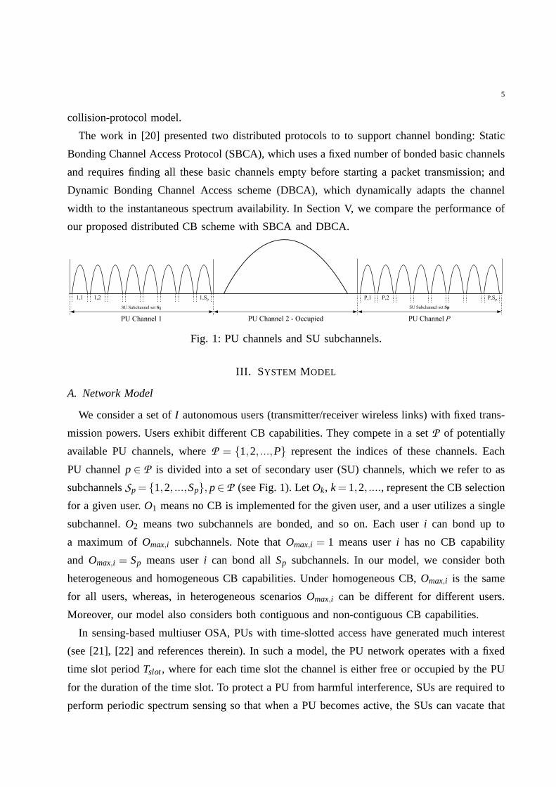
Fig. 1: PU channels and SU subchannels.
III. SYSTEM MODEL
A. Network Model
We consider a set ofI autonomous users (transmitter/receiver wireless links) with fixed trans-
mission powers. Users exhibit different CB capabilities. They compete in a setP of potentially
available PU channels, whereP = {1,2, ...,P} represent the indices of these channels. Each
PU channelp∈ P is divided into a set of secondary user (SU) channels, which we refer to as
subchannelsSp= {1,2, ...,Sp}, p∈ P (see Fig. 1). LetOk, k= 1,2, ...., represent the CB selection
for a given user.O1 means no CB is implemented for the given user, and a user utilizes a single
subchannel.O2 means two subchannels are bonded, and so on. Each useri can bond up to
a maximum ofOmax,i subchannels. Note thatOmax,i = 1 means useri has no CB capability
and Omax,i = Sp means useri can bond allSp subchannels. In our model, we consider both
heterogeneous and homogeneous CB capabilities. Under homogeneous CB,Omax,i is the same
for all users, whereas, in heterogeneous scenariosOmax,i can be different for different users.
Moreover, our model also considers both contiguous and non-contiguous CB capabilities.
In sensing-based multiuser OSA, PUs with time-slotted access have generated much interest
(see [21], [22] and references therein). In such a model, thePU network operates with a fixed
time slot periodTslot, where for each time slot the channel is either free or occupied by the PU
for the duration of the time slot. To protect a PU from harmfulinterference, SUs are required to
perform periodic spectrum sensing so that when a PU becomes active, the SUs can vacate that
6
channel. An SU determines whether the channel is free or occupied by the PU at the beginning
of every time slot by sensing the channel for a periodTsense. The SU may utilize the channel
only if it is determined to be free, and may subsequently transmit for the remainder of the time
slot Tdata= Tslot−Tsense.
Broadly speaking, two approaches can be taken to effectively utilize available subchannels.
One is the multi-channel technique in which multiple frequency channels are used for communi-
cations. The other is CB, in which multiple frequency channels are bonded into a single channel
[23]. CB techniques are widely used in shared channels, suchas the 5 GHz unlicensed band [24].
In our work, we focus on the second approach. When a user finds two or more (contiguous or
non-contiguous) subchannels free for communications, it bonds these subchannels into a single
channel and transmits a larger packet.
In our model, SUs are assumed to be synchronized. This can be done using one of several
available techniques. For example, synchronization beacons can be provided by a spectrum
manager, such as the spectrum access system (SAS) suggestedby FCC [25]. Another possibility is
to utilize a primary systems’ beacon transmissions for synchronization. Several wireless systems
periodically broadcast beacons to their users, and as SUs sense PU activity, they can overhear
these beacons and use them to synchronize.
B. SINR and Collision-protocol Models
Under the SINR model, if the received SINR is greater than a thresholdγ0, a transmission
is considered to be successful. The value ofγ0 varies from one wireless system to another. It
depends on various parameters such as the transmit power, coding and modulation scheme, and
bandwidth utilized, etc. In practice,γ0 should be selected to achieve reasonable communication
performance between users. For the SINR model, we consider an additive white gaussian noise
(AWGN) channel where the received signal strength at a receiver i from transmitterj is [26]:
Pr,i j = P0,i j
(di j
d0,i j
)−α(1)
wheredi j ≥ d0,i j is the distance of receiveri from transmitterj. The reference received power
level P0,i j at the close-in distanced0,i j = max{2D2i
λi,Di,λi} of receiver i from transmitter j is
given by [26]:
P0,i j =Pt, jGt, j Gr,iλ2
i
(4πd0,i j )2 (2)
whereDi is the length of the receiver antenna,λi is the wavelength of the center frequency,
Pt, j and Gt, j are the transmit power and transmit antenna gain, respectively, for transmitterj,
7
andGr,i is the receive antenna gain. The SINR at the receiver of useri is calculated as follows:
γi =Pr,i j
(I∑
k=1,k6= jPr,ik
)
+N0Wi
(3)
where Pr,ik is the interference power from transmitterk at receiveri (depends on overlap of
subchannel selection),N0 is noise power spectral density, andWi is the bandwidth of the
subchannel utilized by useri. Loss of communication only occurs whenγi < γ0. In Eq. (3),
the interference power from transmitterk to receiveri is obtained as follow. We calculate the
fraction of the interferer’s subchannels that the receiveris receiving on, either directly or through
adjacent subchannels. For example, consider the situationat a receiver that is affected by only
one interferer. Suppose that the interferer is transmitting on subchannels 1 and 2 and the receiver
is receiving on subchannels 2, 3, and 4. Assume that the interferer divides its transmit power
equally over subchannels 1 and 2 then the receiver is directly impacted by 50% of the interferer’s
transmit power. Moreover, the receiver may also get adjacent channel interference (ACI) from
interferer’s subchannel 1, corresponding to 50% of the interferer’s transmit power scaled down
by the ACI factor (ACI factor will be 0 if ACI effect is not modeled). For example, if the ACI
factor is 0.05 (-13 dB), the receiver for the above mentionedscenario is impacted by 50% +
50%*0.05 = 52.5% of the interferer’s power. If the receiver is tuned to subchannel 3 only, it
would only receive ACI from subchannel 2 corresponding to 50%*0.05 = 2.5% of the interferer’s
power.
We also consider a collision-protocol model when evaluating the performance of our proposed
CB methods. In this model allI users are assumed to be close to one another, and they all
can interfere with each other. When multiple transmitters transmit over the same channel or
subchannel, a collision occurs, i.e., the data frames are lost for all colliding users. In contrast
to the SINR-protocol model, the collision-protocol model does not take into account the SINR
values in determining packet losses.
C. Contiguous and Non-contiguous CB Selection Models
In our work, we consider two possible CB models: (1) users select subchannels for CB such
that selections are limited to adjacent subchannels, as in some WLANs [3]. Moreover, they are
non-overlapping CB selections with respect to the sameCB order, where CB order represents
the number of subchannels bonded by a SU, andmaximum CB orderrepresents the maximum
number of subchannels that a SU can bond; and 2) users can bondboth adjacent/non-adjacent

8
subchannels, and the selections can be also made out of overlapping subchannels with respect
to the same CB order.
For the first model, the number of possible CB selections for agiven CB orderOk is ⌊SpOk⌋.
Let the set of all possible CB selections in a given channelp for Ok=1 to Ok=max be defined as:
Σ(p) =
{Set ofO1 selections
︷ ︸︸ ︷{{1},{2}, ...,{Sp}
},
Set ofO2 selections︷ ︸︸ ︷{{1,2},{3,4}, .....
}
, ...................,
Set ofOmax selections︷ ︸︸ ︷{{1,2, ...,Omax},{Omax+1,Omax+2, ...,2Omax}, .......
}}
(4)
For example, if any overlapping/non-overlapping combination of adjacent subchannels were
allowed for a given CB orderOk=2, a user who bonds two out of four available subchannels could
also select the pair(2,3) in addition to the non-overlapping pairs(1,2), and (3,4). However,
(2,3) partially overlaps with both(1,2) and (3,4). Hence, for total available four subchannels
and forOk=2, only pairs(1,2), and(3,4) are allowed under the first model. Under this model, by
limiting the CB selections to adjacent and non-overlappingsubchannels, the complexity of the
CB selection search is reduced. However, the number of available CB selections is also reduced.
The restrictions of the first model are relaxed in the second model, as users can now bond
adjacent and non-adjacent subchannels and also overlapping ones. For the second CB model,
the number of possible CB selections for a given CB orderOk is therefore(Sp
Ok
), and the number
of all possible CB selections in a given channelp for any CB order (fromOk=1 to Ok=max) is
∑maxk=1
(SpOk
). Furthermore, the setΣ(p) of all possible CB selections in a given channelp for Ok=1
to Ok=max is simply the set of all combinations of sizek= 1,2, · · · ,kmax.
IV. CHANNEL BONDING METHODS
When designing an efficient CB technique, one must consider how interference from other
users impacts data reception at a given user. In this section, we first consider the SINR-protocol
model in the design of efficient distributed CB techniques among users with heterogeneous CB
capabilities. Later on, we consider the collision-protocol model in designing such techniques.
Finally, for comparison purposes, we present a centralizedmethod where a centralized entity
makes CB decisions.
9
Select subchannel set and
and associated PU channel
Select another
PU channel
to measure
its subchannels
quality
Calculate &
Select the PU channel
associated with the
subchannel set
selected for access
Initialize subchannel access
probabilities
Set highest channel bonding order
Set
Enter explore state
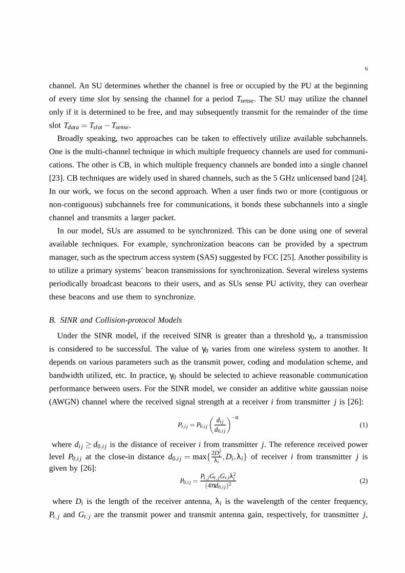
Fig. 2: πAut Method.
A. πAut Method
In the proposedπAut, while searching for spectrum opportunities, users utilize only limited
feedback, specifically, indication of a successful transmission, collision, or no transmission, to
autonomously arrive at CB selections that minimize the likelihood of harmful interference with
one another. The flow diagram forπAut is presented in Fig. 2. To account for traffic dynamics,
the CB algorithm can be executed periodically or when triggered by changes in traffic. Existing
CB selections can be used to initialize the algorithm so thatat re-execution time, the currently
used subchannels will be a subset of the highest CB order.
We now explain the main steps inπAut method and the motivation behind the parameters used:
• Upon becoming active, SUi sets its current CB order toOmax,i , i.e., it first considers, its
maximum CB capability, and it initializes its subchannel selection probabilities for a channel
10
p as:
P(p)ini =
(1−θp)
(P∑
p=1θp)
(
[1
|σ(p)k=max|
,1
|σ(p)k=max|
, ....]
)
∀p∈ P (5)
whereθp is the average PU occupancy in channelp andσ(p)k is the set of orderk subchannel
sets of PU channelp. In practice,θp can be provided by a spectrum manager, such as a
spectrum access system (SAS) as proposed by the FCC. For example, recently the FCC
has suggested the use of environment sensing capability (ESC) devices in the vicinity of
PUs [27]. These devices measure the channel occupancy of PUsas well as the aggregate
received power from SU transmissions to avoid any potentialinterference from SUs onto
PUs. However, in the absence of knowledge ofθp, an SU can initialize subchannel selection
randomly with uniform distribution. After initializationthe SU enters the ‘explore’ state and
setsβi = 1, whereβi refers to the statistical (long term) average ofβi . βi is the ratio of
noise power at receiveri to the sum of interference from all transmitters (excludingits own
transmitter j) and noise power at receiveri:
βi =Ni
Ni +I∑
k=1,k6= jPr,ik
(6)
βi is measured by taking mean of theβi values sampled across subchannels that have
been visited by a user. As the data rate is directly proportional to the SINR, it would be
logical for the channel quality metric to be a function thereof; however, the SINR of the
current subchannel tells us nothing about the state of othersubchannels. Furthermore, a low
SINR could be caused by a low signal to interference ratio (SIR), by a low SNR, or by a
combination of both. For example, a low SINR could be caused by the distance between
transmitter and receiver (low SNR). If the user is experiencing low SNR as a result of this,
then it is unlikely that switching subchannels will result in any improvement in the data rate,
and will instead lead to increased system overhead through excessive signalling. However,
in the case of a low SIR caused by high levels of interference,switching subchannels could
improve the data rate, provided that another subchannel with a lower interference level is
available. A low SIR can also be related to a specific CB selection, as it is possible that the
SU made a poor CB selection due to several other interfering users selecting all or some of
the channels in the CB selection. In this case, making other CB selections can help improve
the performance. The proposedβi takes into account such SINR-related factors. In some
11
scenarios, low SNR could also be the result of significant frequency-selective fading over
the current subchannel(s). Possible mobility of users (or changes in the environment) will
over time average out the fading effect. In these cases, the SNR could be measured over
several time slots to average out fading, so that SNR dependsmainly on the transmitter-
receiver distance for all subchannels. Also, if the coherence bandwidth is much less than
the subchannel bandwidth, then averaging out of fading willoccur in the frequency domain
(different subchannels will likely exhibit similar SNR values for given distance) and no
time-domain averaging is required.
To obtain βi , we need to measure the noise levelNi . One way is to use receivers that
can switch the input chain to use internal termination, which greatly reduces the incoming
signals and provides mostly a signal-free estimate of the noise level. Another way is to
use signal processing techniques to locate signal-free samples and use them for noise-floor
estimation. One such technique is Minimum Value Processing(MVP), in which one obtains
a running average of the square of the received signal, obtains a large number of samples
of it, and selects their minimum value. The key in avoiding a negative bias is to use a
sufficiently large averaging window. The obtained minimum value is the estimated noise
floor. Other noise-floor estimation techniques include the forward consecutive mean excision
(FCME) algorithm [28], which has been used in many measurement studies [29].
Note that in the first time slot when a user becomes active, it has no knowledge ofβi for
different subchannels. In this case, useri can either start with a pessimistic value, e.g.,
βi = 0, or an optimistic value, e.g.,βi = 1. In our work, we consider the optimistic value.
Note that immediately after becoming active, the user measuresβi for different subchannels
over next time slots and update its estimate.
• In subsequent time slots, useri can be either in the ‘explore’ or ‘persist’ state. When user
i is in the explore state, it randomly selects a subchannel CB set. When useri is in persist
state, it utilizes the previously used subchannel set. The user then senses the associated PU
channel of the selected subchannel set over the periodTsense. One of two possibilities can
occur: (1) The PU channel is found to be occupied; or (2) The PUchannel is found to be
free.
• If the PU channel is found to be occupied, useri remains quiet and utilizes the remaining
time period of the frame to measure theβi (see Eq. 6) over another PU channel that is
randomly selected from the remaining channels.
• If the PU channel is found to be free, data is transmitted for the durationTdata. One of two
12
possibilities occur: 1) Successful transmission; or 2) Unsuccessful transmission.
• If the SINR at the intended receiver is greater than a threshold valueγ0, then the transmission
is successful and an acknowledgement (ACK) will be sent to the user. In this case there are
two possibilities: (1) the user is currently in the explore state and will enter persist state; and
(2) the user is currently in the persist state and will enter the explore state with probability
Pexplore. It is important to note that due to the relatively smaller size of the ACK packets, it is
less likely that the ACK packets could also experience packet losses. Also, to reduce further
ACK packet loses they may be transmitted with more robust coding/modulation/control
rate techniques. For example, in [30] the authors have suggested the use of low rate ACK
transmission where packet ACK are sent with lower control rate of 1Mbps. Lower rate for
ACK can lead to lower requirement for SINR tolerance.
Pexplore=
√
1Cβ
βi(1−βi)ζ (7)
whereζ > 0 is a constant, andCβ represents a counter which counts the number of time
slots sinceβi,new≯ βi,old.
Motivation for the use of the channel quality metric βi and Pexplore
After making a successful CB selection, the user may later beable to identify better CB
selection than the current one. To take into account this, a user after successful transmission
enters the explore state with probabilityPexplore. It is important to note that to avoid constant
exploration (and hence constant subchannel switching),Pexplore must be decreased after
making a successful CB selection. The probability Pexplore takes into account the data rate on
the current subchannel and the likelihood of discovering a better subchannel. This is achieved
by utilizing the proposed channel quality metricβi . In the presence of no interference
βi equals to 1, while as interference increasesβi → 0. As the value ofβi decreases, the
likelihood of achieving a higher data rate by changing subchannel assignment increases.
Therefore,βi reflects how beneficial changing subchannel assignment can be, while being
strictly between the values of 0 and 1. The constantζ > 0 is a weighting factor. Whenζ= 1,
the parameter has no impact on thePexplore. However, whenζ > 1, Pexplorestarts decreasing.
A careful choice ofζ is required: if it is set to a very high value, then we may not beable
to achieve convergence to a state where users experiences the highest valueβi ; on the other
hand, if it is set a too low value, then it encourages more exploration and hence subchannel
switching more often among the users.βi reflects the state of the channels visited by a user
13
over period of time andβi → 0 means that the channels are of poor quality. In this case
further exploration can incur only overhead costs in terms of subchannel switching. Hence,
in Eq. 7 Pexplore→ 0 also asβi → 0. Moreover, Pexplore should also take into account the
fact that if a user after finding subchannel selections for utilization is not able to find new
subchannel selections offering an improvement then the user should explore less often as
exploration incurs cost in terms of subchannel switching.
• If the SINR at the intended receiver is less than the threshold valueγ0 then the transmission is
unsuccessful and no ACK will be received by the user. In this case there are two possibilities:
(1) The user has been successful in a previous transmission using the subchannel selection
and is currently in persist state, it will persist after failure with the probability Ppersist in
the next slot. Ppersist for such cases is given by:
Ppersist= 1−
(1
(TSCS− (Tf ail −1))−
1TSCS
)
(8)
whereTSCS is the number of time slots the user has been utilizing the current subchannel
selection (SCS) set. Note thatTSCSafter first failure is always greater than one.Tf ail is the
number of time slots the user has had failed transmission on the current subchannel. Note
that Ppersist= 1 in the first time slot after a failed transmission, and decreases with each
further failed transmission.
Motivation for the use of Ppersist: Being in the persist state means the user has been
previously successful on its current subchannel set. When the user experiences a failed
transmission in the current time slot it can be that at least one interfering user has attempted
to utilize at least one subchannel in the current set. There are two outcomes in this case:
1) that all interfering users experienced a failed transmission and were unsuccessful, or 2)
at least one of the interfering users had a successful transmission and has entered persist
state. In the first case, all the interfering users will continue in explore state and attempt to
utilize different subchannel sets in the next time slot. This will likely lead to a successful
transmission as interfering users will not select the same subchannel selection and the user
can get improved SINR. In the second case where at least one ofthe interfering users is
successful on the subchannel set and enters persist state, the current user of the subchannel
set may or may not continue to have failed transmissions as aggregate interference levels may
change depending on the subchannel selections of other interfering users. As the number
of sequential failed transmissions increases, the more likely it is to be caused by at least
one persisting user in the current subchannel set, and not users exploring the subchannel
14
set. In this case, it is desirable to enter explore state and find another set of subchannels to
utilize. We therefore base the probability Ppersist as a function ofTSCSandTf ail .
2) The second possibility is that the user is in explore stateand was unsuccessful on this
subchannel. If the user has CB selectionOk, wherek> 1 it will reduce its CB order by 1
with probability Preduce, it then sets the probability of accessing the current subchannel set
in the next time slot to 0. Preduce (the probability of reducing CB order by 1) is given by:
Preduce=βi +Tlim(1− βi)
2(9)
whereTlim is defined as:
Tlim = min
{
1,Tactive
δ
}
(10)
whereTactive is the number of time slots the user has been active andδ > 0 is a parameter
set sufficiently high that the estimateβi accurately reflects the state of the channels in use.
For example,δ = 1 means that even when the user has been recently active in thenetwork
(active only a few time slots),βi will still have high influence on reducing the CB order
when a user gets unsuccessful in transmissions. However,βi is statistical average and it
would be good for a user to collect more samples ofβi to have better long term average
value. Hence, a higher value forδ allows a user to take decision of reducing CB order
based on better estimates ofβi .
Motivation for the use of Preduce : Even in the presence of no interference it is possible that
channel quality between a transmitter and its receiver is degraded due to bad signal-to-noise
(SNR) ratio. For example, it could be caused by the distance between a transmitter and its
intended receiver (low SNR). In such scenarios it can be lessefficient to communicate with
a higher CB selection, as lower CB selection can improve the coverage. Reducing the CB
order in such scenarios may be desirable as a transmitter mayspend the same amount of
power in a smaller bandwidth and hence may improve its SNR. The probability Preduce
ensures that when transmissions are failed the probabilityof reducing CB order is high
whereβi is high, in which case a low SNR is likely the cause of the failed transmission. In
the case of lower values ofβi where interference may be the cause of failed transmission,
the probability of reducing CB order increases with failed transmissions. This is due to the
reason that as a user explores channels it mostly measures low values ofβi which in turn
decreases the estimateβi . Low values ofβi means most of the subchannel are poor quality
and by reducing CB order a user may increase its SINR.

15
• If a user enters explore state after a previously successfultransmission and finds a subchan-
nel set on which it can communicate successfully, it will persist with the new subchannel
set if βi of the new set is greater thanβi of the previously utilized set. Otherwise it will
persist with the previous subchannel set.
B. TheπSig Method with SAS Coordination
To protect the PUs from interference and to facilitate the users seeking to utilize the spectrum
for secondary usage, recent approaches to spectrum sharinghave suggested the use of a spectrum
manager entity, such as SAS [10]. In SAS based systems multiple independent users may be
required to register their information (which can include CB capabilities, location information,
etc) and also to inform their subchannel selection decisions to a SAS [10]. In our work, we
ask the following question. In the presence of a SAS system, which has such user information
available; can it be utilized for efficient CB selections? Weparticularly focus on the scenarios
where the information can be made available with minimum overhead.
Under the collision-protocol model, where only a single user can utilize a given channel when
in interference range, a SAS entity with knowledge of user channel and subchannel selections
can help users to converge quickly to subchannel selectionsthat minimize the probability of
collisions. This can be achieved withlow overhead information exchange; for example, a SAS can
inform users with a single bit if they should utilize a given subchannel. A user can inform the SAS
of it’s channel and subchannel selections only when it changes it’s selection. This information
exchange between the SAS system and the users can be achievedusing the concept of anchoring
the control channel which is recently proposed in [4]. In this approach, through aggregation, the
connectivity on the opportunistic access spectrum always comes with the connectivity on the
more reliable spectrum. The control signaling always happens on the reliable channel such as a
licensed or an unlicensed channel with no incumbent. Note that the proposed method does not
allow for any information exchange between users. Also, in the proposed method, we consider
interference range to be twice the transmission range of a user. This is a typical assumption in
standard literature when considering interference ranges.
It is important to note that unlike the collision-protocol model, under the SINR-protocol model,
a SAS entity using the above low overhead information exchange to obtain the knowledge of all
users’ SCS selections at a given time instant can be of littlehelp to users to converge quickly
to those selections that minimize the probability of interference. This is due to the reason that
different users can have different sets of interferers thatcan cause loss of communication, and

16
hence the universal knowledge of SCS selections obtained bythe SAS entity (as explained above)
may not lead to efficient SCS selections.
The important steps involved in the proposedπSig method are explained below in detail.
1) SAS information exchange:Using knowledge of user locations, the SAS determines the
users that are within interfering range of a particular user. Based on this, and the subchannel
selections of the users that are within interfering range ofa user; the SAS generates a subchannel
status bit-map for each user. Each element of the bit-map corresponds to a subchannel, where
a value of 1 indicates that the subchannel is singleton, i.e., occupied by only a single user, that
is within the interference range of the user. A value of 0 indicates that the subchannel is either
free, or utilized by 2 or more users within the interfering range of the user.
πSig Methoda) Each useri Module
Initialize Ok=max, and each element of the local binary subchannel status bitmap to 0Update binary subchannel status bitmap if new bit map received fromSASSelectuniformly at randomOk non-singleton subchannels associated with a PU channelpInform Inform SAS of the subchannel selectionSensethe PU channel associated with the selected subchannels
if PU is presentthenEnter State= persist, Return toSenseand wait for the next time slot
elseTransmit dataif Successful communicationthen
Enter State= persist, Return toSenseand wait for the next time slotelse
Enter State= exploreCheck for the availability of at least one other non-singleton subchannel set of orderOkReduceOk → Ok−1 whenk≥ 2 and no non-singleton subchannel set of orderOk is available.Return to Update
end ifend if
b) SAS Module
Collect subchannel selections of every useriGeneratebit-map of subchannel status, non-singleton channel subchannels= 0, singleton channels= 1Communicate bitmap to usersUpdate subchannel selections when received from a user andReturnto Generate
2) Subchannel selection and utilization:
• A user initializes a local binary subchannel status bit-map, the length of which is equal to
the total number of usable subchannels. Each element of the bit-map is initialized to 0. The
user sets it’s current CB orderOk,i = Omax,i .
• After the initialization phase, a user then selects randomly with uniform probability anOk,i
order subchannel set out of those subchannel sets that are currently free and its associated
PU channel. The user communicates its subchannel selectionto the SAS and senses the
17
selected PU channel for the time periodTsense. One of two possibilities can occur: 1) The
PU channel is found to be occupied; or 2) The channel is free.
• If the channel is found to be occupied, the user remains quiet. If the channel is found
free, data is transmitted. One of two possibilities occur: 1) successful transmission; or 2)
unsuccessful transmission.
• If the transmission is successful then the user enters a persist state and selects the same
subchannel set in the next time slot.
• If the transmission is unsuccessful then the user remains inan explore state. If there is no
other subchannel sets of the orderOk,i with status 0, according to the local binary subchannel
status bit-map , then the user reducesOk,i by 1.
• The user updates the local binary subchannel status bit-mapaccording to the bit-map
received from the SAS, and returns to the subchannel selection step.
C. πCen centralized method for subchannel selection
To establish a baseline for comparing the results obtained from the proposedπAut and πSig
methods, we consider aπCen centralized method to the CB selection problem. A centralized CB
and subchannel allocation solution that performs an exhaustive search over a set of all possible
subchannel sets forI users with different distances, subchannel and interference conditions is
computationally intensive and becomes numerically untractable beyond a certain number of users.
The πCen method finds a subchannel assignment for all users in the network that maximizes the
data rate of the network such that each user is able to successfully communicate. The steps
involved in theπCen method are explained in detail as follows:
• Step 1:The method works by first assigning a differentO1 subchannel set to each of the
I users. When no unused subchannels remain, the centralized method goes through all
subchannels one-by-one and assigns a subchannel that maximizes data rate.
• Step 2:The method then attempts to increaseOk by trying one by one different CB orders
Ok for a useri. For instance, if the useri has Omax,i = 3 then the method first tries all
subchannel sets ofO2 for the useri and then all subchannel sets ofO3. While trying each
subchannel set, if there are any interferers on this new subchannel set, it attempts to relocate
the interferers by trying all possible subchannel sets (of their currentO j ) assignments for the
interferers. The method calculates data rate for each roundof increase inOk. However, the
subchannel assignments are only updated if the total data rate has increased. The assignment
that maximizes the data rate is utilized. The above step of attempts to increaseOk is repeated
18
one by one for all the users in the network.
• Step 3:Once step 2 is performed for allI users, the method checks whether at least one
user has a different subchannel assignment after the current iteration. If this is true then
an improved subchannel assignment has been found in the current iteration for at least 1
user, and the method proceeds to the next iteration in which step 2 is repeated again. If this
is false then no improved subchannel assignments were foundfor any user in the current
iteration, and the method ends.
0 20 40 60 80 1000,92
0,94
0,96
0,98
1
Network Instance
τcen/τopt
(a) 1 channel / 4 SUs
0 20 40 60 80 1000.99
0.992
0.994
0.996
0.998
1
Network Instance
τcen/τopt
(b) 2 channels / 8 SUs
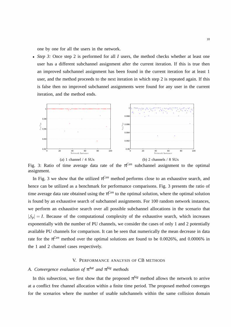
Fig. 3: Ratio of time average data rate of theπCen subchannel assignment to the optimalassignment.
In Fig. 3 we show that the utilizedπCen method performs close to an exhaustive search, and
hence can be utilized as a benchmark for performance comparisons. Fig. 3 presents the ratio of
time average data rate obtained using theπCen to the optimal solution, where the optimal solution
is found by an exhaustive search of subchannel assignments.For 100 random network instances,
we perform an exhaustive search over all possible subchannel allocations in the scenario that
|Sp| = I . Because of the computational complexity of the exhaustivesearch, which increases
exponentially with the number of PU channels, we consider the cases of only 1 and 2 potentially
available PU channels for comparison. It can be seen that numerically the mean decrease in data
rate for theπCen method over the optimal solutions are found to be 0.0026%, and 0.0006% in
the 1 and 2 channel cases respectively.
V. PERFORMANCE ANALYSIS OFCB METHODS
A. Convergence evaluation ofπAut and πSig methods
In this subsection, we first show that the proposedπSig method allows the network to arrive
at a conflict free channel allocation within a finite time period. The proposed method converges
for the scenarios where the number of usable subchannels within the same collision domain

19
is |Sp| ≥ I users. We also provide the expected number of time slots required to arrive at a
conflict-free allocation using theπSig method. For analytical convergence analysis, we consider
a difficult scenario where allI users are within the same collision domain, and|Sp|= I .
Let E[T(n)] denote the expected number of time slots required for a network of I users to
arrive at a conflict-free CB allocation, starting from the initial staten. When I users operate in
the network then using theπSig method, the stochastic subchannel selection process in this case
can be modeled as a finite-state Markov chain with a finite setS . Let
S = {n,n−1,n−2, · · · ,1}, (11)
where each element ofS is a state representing the number of users randomly selecting a
subchannel in a time slot. SetS forms the state space of the subchannel selection process.
For instance, whenI = 4 users operate in the network, there are 4 states in the Markov chain,
S = {4,3,2,1}, a state(n= 4) means that all 4 users randomly perform a selection in a time
slot, a state(n= 3) means that 3 users randomly select while 1 user does not perform random
selection in a time slot, a state(n= 2) means that 2 users randomly select while 2 users do not
perform random selection in a time slot, and state(n= 1) is the state in which no user performs
random selection.
Definition 1. A state i in a Markov chain is called absorbing if the chain must stay in state
i with probability 1 once it has visited that state. The states that aren’t absorbing are called
transient.
Definition 2. A Markov chain is called absorbing if every state i has a path of successors
i −→ i′ −→ i′′ −→ ... that eventually leads to an absorbing state.
The above Definitions 1 and 2 are given in [31]. The initial state of the stochastic CB selection
process isn= I , in which all I users randomly perform a selection in a time slot. If the Markov
chain is currently in statei it moves to statej at the next step with a transition probability denoted
by Pi j . We say that in a given time instant, the process moves forward when the number of users
performing random selection changes due to one or more usersselecting singleton subchannel.
It stays in the same state if the number of users performing random selection remains the same.
For example, whenI = 4 users, the process starts in staten = 4. In the next time slot, it will
remain in staten= 4 if no user selects a singleton subchannel, it will move to state n = 3, if
one user selects a singleton subchannel, and so on. When all users have selected a singleton
subchannel then they settle down in terms of subchannel selections. Hence, in the next time

20
instants the network remains in that state. Hence, the considered Markov chain is absorbing in
which state 1 is absorbing and all other states are transient.
Proposition V.1. For an absorbing Markov chain, the probability that the chain eventually enters
an absorbing state (and stays there forever) is 1.
The staten= 1 is called absorbing as transition probability from state 1to 1 is one. In other
words, once the system hits state 1, it stays there forever not being able to escape. This is due to
the reason that when all users have selected a singleton subchannel, i.e., a subchannel occupied
by only a single user, they settle down in terms of subchannelselections in this conflict-free
state. Hence, in the next time instants the network remains in that state. Hence, the considered
Markov chain is absorbing in which state 1 is absorbing.
Proposition V.2. For an absorbing Markov chain, the time that it takes for the chain to arrive
at a certain absorbing state (a random variable) has finite expected value.
The transition probability from any statei to j, given i 6= 1, is greater than zero, and also the
transition probability from the statei = 2 to i = 1 is greater than zero. Hence, it takes finite time
to reach the absorbing state, i.e., the staten= 1.
The above propositions 1 and 2 are proved in [31].
To calculate transition probability from statei to j for the considered stochastic subchannel
selection process, we need to consider the probability thatwhen in a state,n users select uniformly
at random randomly out ofn subchannels, exactlyr of these users will select singleton selections,
i.e. a subchannel occupied by only a single user. This probability is given by [32]:
p(n, r) =n
∑s=r
(n!
(n−s)!
)2 1(s− r)!r!
(n−s)n−s
nn (−1)s−r,
0≤ r ≤ n.
(12)
Let P represent the state transition probability matrix of an absorbing Markov chain in canonical
form:
P=
(
Q R
O I
)
,
where I is an identity matrix,O is a matrix with all zero entries,R is the matrix of transitionprobabilities from transient to absorbing states andQ is the matrix of transition probabilitiesbetween the transient states. The transition probability matrix P for the absorbing Markov chainof subchannel selection process can be constructed using Eq. 12. For example, forI = 4, P can

21
be calculated using Eq. 12 as follows:
P=
Q R
state 4 state 3 state 2 state 1
state 4 P44 = p(4,0) P43 = p(4,1) P42 = p(4,2) P41 = p(4,4)
state 3 P34 = 0 P33 = p(3,0) P32 = p(3,1) P31 = p(3,3)
state 2 P24 = 0 P23 = 0 P22 = p(2,0) P21 = p(2,2)
state 1 P14 = 0 P13 = 0 P12 = 0 P11 = 1
O I
Using the standard theory of absorbing Markov chains (presented in [31]), one can calculate
E[T(n)] for the subchannel selection process starting from the initial staten as follows. LetN
be fundamental matrix which is given byN = (I −Q)−1, whereI is an identity matrix andQ is
the matrix of transition probabilities between the transient states. In [31], it has been shown that
the i j -entry of the matrixN gives the expected number of times the Markov chain is in state j,
given that it starts in statei. Hence, using theπSig method, when the network starts from the
initial staten= N, E[T(n= N)] until convergence to a conflict-free allocation for the network
is given byE[T(n= N)] = ∑Nj=1N1, jCj , whereN1, j is the jth entry of the first row of matrixN,
andCj is the jth entry of vectorC. All entries of C are 1.
0 5 10 15 20 25 302
4
6
8
10
12
14
I
Number
ofTim
eSlots
πSig Analytical
πSig Simulated
πFB Simulated
πAut Simulated
Fig. 4: Expected time to converge to conflict free subchannelselections of theπSig and πFB
methods as a function ofI users, under collision-protocol model. The number of availablesubchannels|Sp|= I , andOmax,i = 1∀i.
In Fig. 4, we compare the results given by the analytical expected time to convergence we
derived in Section V-A and the calculated expected time to convergence from a Monte Carlo
simulation. Observe that the values calculated from Monte-Carlo simulations agree perfectly
with those obtained from the presented analytical model.
In Fig. 4 we also evaluate and compare the expected time to converge (E[TTC]) to conflict free
subchannel selections (in terms of time slots), of theπSig method both analytically and simulated,
with a method proposed in [21], as a function ofI increasing users. Moreover, we consider a
difficult scenario under collision-protocol model where the number of available subchannels|Sp|
22
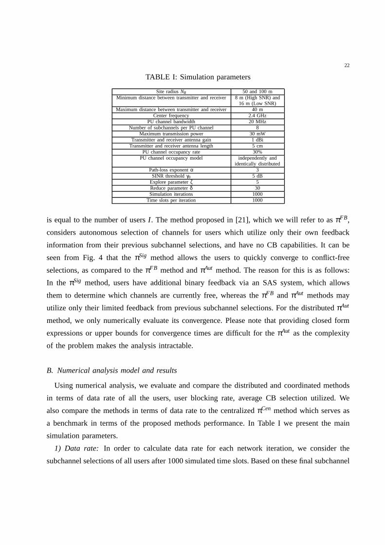
TABLE I: Simulation parameters
Site radiusNR 50 and 100 mMinimum distance between transmitter and receiver8 m (High SNR) and
16 m (Low SNR)Maximum distance between transmitter and receiver 40 m
Center frequency 2.4 GHzPU channel bandwidth 20 MHz
Number of subchannels per PU channel 8Maximum transmission power 30 mW
Transmitter and receiver antenna gain 1 dBiTransmitter and receiver antenna length 5 cm
PU channel occupancy rate 30%PU channel occupancy model independently and
identically distributedPath-loss exponentα 3SINR thresholdγ0 5 dB
Explore parameterζ 5Reduce parameterδ 30Simulation iterations 1000
Time slots per iteration 1000
is equal to the number of usersI . The method proposed in [21], which we will refer to asπFB,
considers autonomous selection of channels for users whichutilize only their own feedback
information from their previous subchannel selections, and have no CB capabilities. It can be
seen from Fig. 4 that theπSig method allows the users to quickly converge to conflict-free
selections, as compared to theπFB method andπAut method. The reason for this is as follows:
In the πSig method, users have additional binary feedback via an SAS system, which allows
them to determine which channels are currently free, whereas theπFB and πAut methods may
utilize only their limited feedback from previous subchannel selections. For the distributedπAut
method, we only numerically evaluate its convergence. Please note that providing closed form
expressions or upper bounds for convergence times are difficult for the πAut as the complexity
of the problem makes the analysis intractable.
B. Numerical analysis model and results
Using numerical analysis, we evaluate and compare the distributed and coordinated methods
in terms of data rate of all the users, user blocking rate, average CB selection utilized. We
also compare the methods in terms of data rate to the centralizedπCen method which serves as
a benchmark in terms of the proposed methods performance. InTable I we present the main
simulation parameters.
1) Data rate: In order to calculate data rate for each network iteration, we consider the
subchannel selections of all users after 1000 simulated time slots. Based on these final subchannel
23
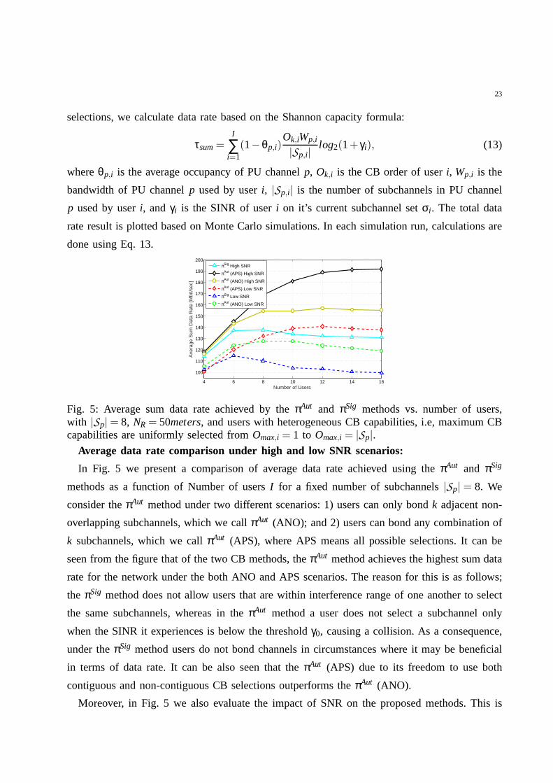
selections, we calculate data rate based on the Shannon capacity formula:
τsum=I
∑i=1
(1−θp,i)Ok,iWp,i
|Sp,i|log2(1+ γi), (13)
whereθp,i is the average occupancy of PU channelp, Ok,i is the CB order of useri, Wp,i is the
bandwidth of PU channelp used by useri, |Sp,i| is the number of subchannels in PU channel
p used by useri, andγi is the SINR of useri on it’s current subchannel setσi . The total data
rate result is plotted based on Monte Carlo simulations. In each simulation run, calculations are
done using Eq. 13.
4 6 8 10 12 14 16
100
110
120
130
140
150
160
170
180
190
200
Number of Users
Ave
rage
Sum
Dat
a R
ate
[Mbi
t/sec
]
πSig High SNR
πAut (APS) High SNR
πAut (ANO) High SNR
πAut (APS) Low SNR
πSig Low SNR
πAut (ANO) Low SNR
Fig. 5: Average sum data rate achieved by theπAut and πSig methods vs. number of users,with |Sp|= 8, NR= 50meters, and users with heterogeneous CB capabilities, i.e, maximum CBcapabilities are uniformly selected fromOmax,i = 1 to Omax,i = |Sp|.
Average data rate comparison under high and low SNR scenarios:
In Fig. 5 we present a comparison of average data rate achieved using theπAut and πSig
methods as a function of Number of usersI for a fixed number of subchannels|Sp| = 8. We
consider theπAut method under two different scenarios: 1) users can only bondk adjacent non-
overlapping subchannels, which we callπAut (ANO); and 2) users can bond any combination of
k subchannels, which we callπAut (APS), where APS means all possible selections. It can be
seen from the figure that of the two CB methods, theπAut method achieves the highest sum data
rate for the network under the both ANO and APS scenarios. Thereason for this is as follows;
the πSig method does not allow users that are within interference range of one another to select
the same subchannels, whereas in theπAut method a user does not select a subchannel only
when the SINR it experiences is below the thresholdγ0, causing a collision. As a consequence,
under theπSig method users do not bond channels in circumstances where it may be beneficial
in terms of data rate. It can be also seen that theπAut (APS) due to its freedom to use both
contiguous and non-contiguous CB selections outperforms the πAut (ANO).
Moreover, in Fig. 5 we also evaluate the impact of SNR on the proposed methods. This is
24
important, as even in the presence of little to no interference it is possible that channel quality
between a transmitter and its receiver is degraded due to lowSNR. One factor that can impact
the SNR is the distance between the users. We consider two scenarios, where the minimum
distance of receivers from their transmitters is no less than 8 m, and 16 m, respectively, and in
both cases a maximum distance is no more than 40 m (between a transmitter and its intended
receiver). The maximum distance is selected so that at this maximum distance a user without CB
can successfully communicate given that there is no interference (based on the other parameters
such as path loss exponent). It is possible that a receiver may be located closer to interfering
transmitters than the 8 m / 16 m minimum distance. Increasingthe minimum distance from 8
m to 16 m reduces mean SNR. We will refer to the case of 8 m minimum distance as the high
SNR scenario, and 16 m case as the low SNR scenario from here on. It can been seen in Fig. 5
that under high SNR theπAut (APS) achieves the highest gain in sum data rate for the network.
0 50 100 150 200
Time Slot
100
110
120
130
140
150
160
170
180
190
200
Ave
rage
Sum
Dat
a R
ate
(Mbi
t/sec
)
ΠAut
DBCA
SBCA
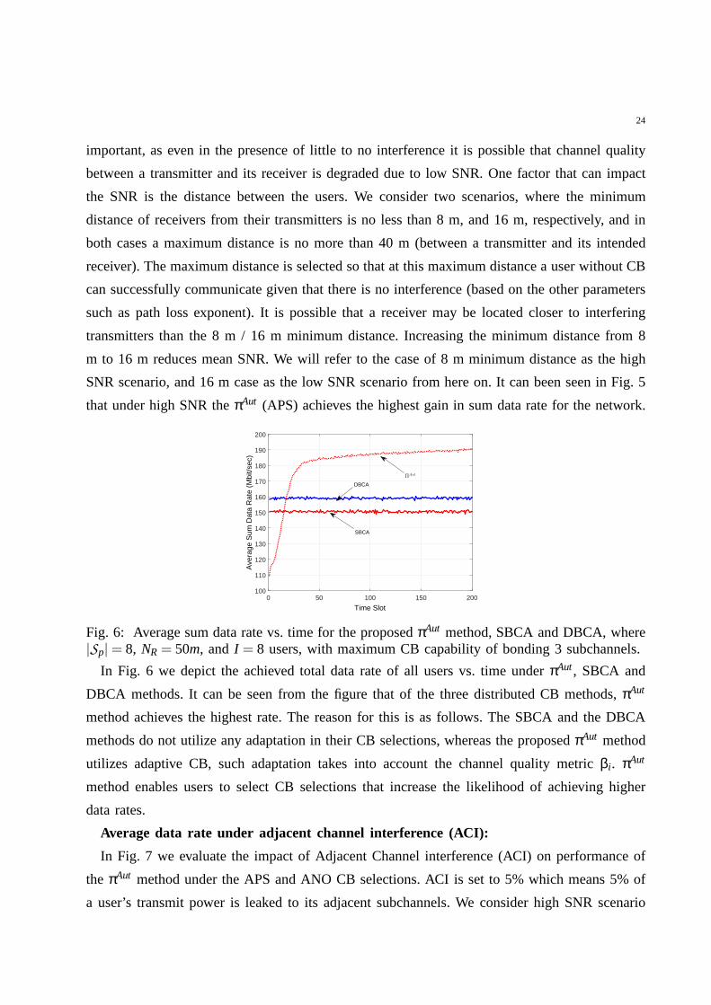
Fig. 6: Average sum data rate vs. time for the proposedπAut method, SBCA and DBCA, where|Sp|= 8, NR = 50m, and I = 8 users, with maximum CB capability of bonding 3 subchannels.
In Fig. 6 we depict the achieved total data rate of all users vs. time underπAut, SBCA and
DBCA methods. It can be seen from the figure that of the three distributed CB methods,πAut
method achieves the highest rate. The reason for this is as follows. The SBCA and the DBCA
methods do not utilize any adaptation in their CB selections, whereas the proposedπAut method
utilizes adaptive CB, such adaptation takes into account the channel quality metricβi . πAut
method enables users to select CB selections that increase the likelihood of achieving higher
data rates.
Average data rate under adjacent channel interference (ACI):
In Fig. 7 we evaluate the impact of Adjacent Channel interference (ACI) on performance of
the πAut method under the APS and ANO CB selections. ACI is set to 5% which means 5% of
a user’s transmit power is leaked to its adjacent subchannels. We consider high SNR scenario
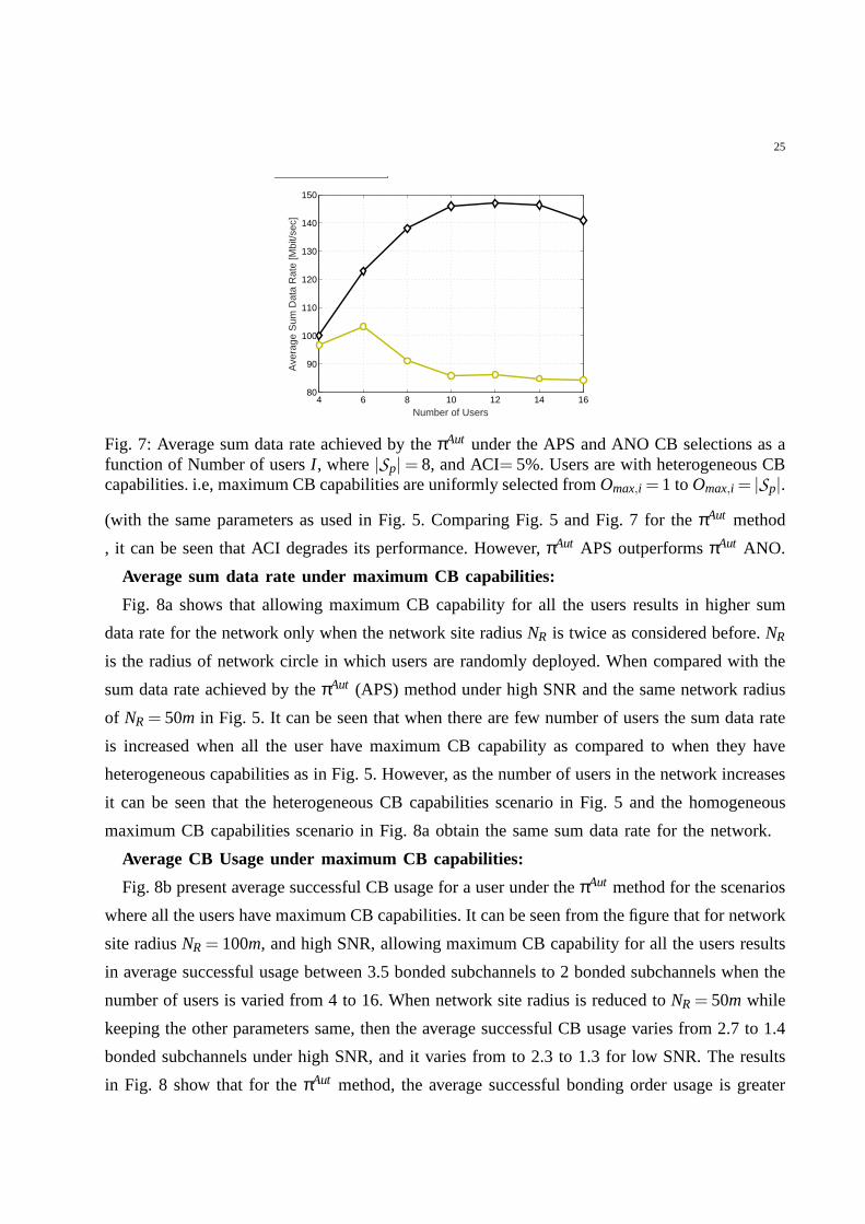
25
4 6 8 10 12 14 1680
90
100
110
120
130
140
150
Number of Users
Ave
rage
Sum
Dat
a R
ate
[Mbi
t/sec
]
Fig. 7: Average sum data rate achieved by theπAut under the APS and ANO CB selections as afunction of Number of usersI , where|Sp|= 8, and ACI= 5%. Users are with heterogeneous CBcapabilities. i.e, maximum CB capabilities are uniformly selected fromOmax,i =1 toOmax,i = |Sp|.
(with the same parameters as used in Fig. 5. Comparing Fig. 5 and Fig. 7 for theπAut method
, it can be seen that ACI degrades its performance. However,πAut APS outperformsπAut ANO.
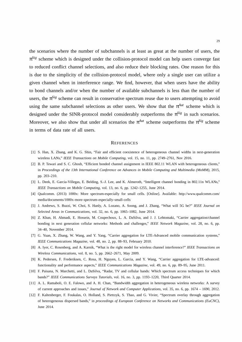
Average sum data rate under maximum CB capabilities:
Fig. 8a shows that allowing maximum CB capability for all theusers results in higher sum
data rate for the network only when the network site radiusNR is twice as considered before.NR
is the radius of network circle in which users are randomly deployed. When compared with the
sum data rate achieved by theπAut (APS) method under high SNR and the same network radius
of NR= 50m in Fig. 5. It can be seen that when there are few number of usersthe sum data rate
is increased when all the user have maximum CB capability as compared to when they have
heterogeneous capabilities as in Fig. 5. However, as the number of users in the network increases
it can be seen that the heterogeneous CB capabilities scenario in Fig. 5 and the homogeneous
maximum CB capabilities scenario in Fig. 8a obtain the same sum data rate for the network.
Average CB Usage under maximum CB capabilities:
Fig. 8b present average successful CB usage for a user under theπAut method for the scenarios
where all the users have maximum CB capabilities. It can be seen from the figure that for network
site radiusNR= 100m, and high SNR, allowing maximum CB capability for all the users results
in average successful usage between 3.5 bonded subchannelsto 2 bonded subchannels when the
number of users is varied from 4 to 16. When network site radius is reduced toNR= 50m while
keeping the other parameters same, then the average successful CB usage varies from 2.7 to 1.4
bonded subchannels under high SNR, and it varies from to 2.3 to 1.3 for low SNR. The results
in Fig. 8 show that for theπAut method, the average successful bonding order usage is greater

26
4 6 8 10 12 14 16
150
200
250
300
350
400
Number of Users
Ave
rage
Sum
Dat
a R
ate
[Mbi
t/sec
]
πAut (APS) Low SNR, NR = 50 m
πAut (APS) High SNR, NR=100 m
πAut (APS) High SNR, NR = 50 m
(a)
4 6 8 10 12 14 160
0.5
1
1.5
2
2.5
3
3.5
4
Number of Users
Ave
rage
Suc
cess
ful B
ondi
ng U
sage
πAut (APS) Low SNR, N
R= 50 m
πAut (APS) High SNR, NR =100 m
πAut (APS) High SNR, NR = 50
(b)
Fig. 8: a) Average sum data rate achieved and b) Average successful CB utilized under theπAut
with APS CB selections for|Sp|= 8. Each user is with the same maximum CB capability whichmeans that each user has the ability to bond all the subchannels.
than one for all studied cases. However, it is also true that as the users to available subchannels
ratio (UCR) increases, the average bonding order that a usercan successfully utilize goes down.
As the UCR increases, ultimately there comes a point where CBbecomes of no benefit to a user
due to high user density, i.e., the user can successfully utilize only one subchannel for access.
This means that the proposed distributed CB method gives either better performance or equal
performance, compared to the scenarios when no bonding is applied. It is important to note
that this degradation in CB performance due to the increasedUCR is common to all channel
bonding/selection techniques [3].
Average sum data rate Comparison with benchmark Centralized method πCen:
In Fig. 9 we present a comparison of the data rate achieved by the distributedπAut and
πSig methods to the data rate achieved using the close to optimal centralizedπCen method. The

27
4 8 12 16 20 24 28 320
200
400
600
800
1000
1200
Number of Users
AverageSum
DataRate[M
bit/s]
πCen High SNR
πCen Low SNR
πSig High SNR
πSig Low SNR
πAut (ANO) High SNR
πAut (ANO) Low SNR
Fig. 9: Average sum data rate vs. number of usersI for the πAut, πSig and theπCen methods.Number of subchannels is increased with the number of users,i.e., |Sp|= I .
results show that of all the CB methods presented, theπAut performs the closest to theπCen
solution. With 4 users and 4 subchannels, whenOmax,i = 3∀i, the average data rate achieved is
approximately 123 Mb/s with theπCen method and 107 Mb/s with theπAut method. In other
words with 4 users, theπAut achieves average data rate of 87% of that achieved by close to
optimalπCen method. The gap in performance between theπAut andπCen methods does however
increase with the number of users. For double the number of users, the performance of theπAut
decreases to approximately 77% of theπCen method, reducing further to 69% with 32 users.
2) User blocking rate:It is logical that as the number of users increases while the number
of subchannels is constant, users will experience higher levels of interference, and some users
will be left unable to communicate on any subchannels withγi > γ0. We consider blocking rate
to be the ratio of the mean number of blocked users per iteration to the total number of users:
Rblocking=Iblocked
I(14)
In Fig. 10 we present a comparison of the blocking rate observed using theπAut under the APS
and ANO selections, and alsoπSig as a function ofI users withOmax,i = 3, again considering
both high and low SNR scenarios. The number of subchannels isfixed |Sp|= 8. As previously
mentioned, users in theπAut method do not select subchannels only when SINR is below the
thresholdγ0. In the scenarios where a user is causing interference to others, but not experiencing
high interference levels, the user may utilize a higher CB order and deprive other users of
successful subchannel selections. As a consequence, the blocking rate of theπAut method as
compared to theπSig method is greater for such scenarios.
The results in Fig. 10 show that the blocking rate of theπSig method is lower than theπAut

28
4 6 8 10 12 14 160
0.1
0.2
0.3
0.4
0.5
0.6
0.7
0.8
Number of users
Blo
ckin
g R
ate
πSig High SNR
πAut (ANO) High SNR
πSig Low SNR
πAut (ANO) Low SNR
πAut (APS) High SNR
πAut (APS) Low SNR
Fig. 10: User blocking rate of theπAut andπSig methods as a function of Number of usersI .
with ANO selections method, when the number of users is less than 16 in the high SNR case, and
10 in the low SNR case. However, its blocking rate is higher than theπAut with APS selections
method. For an increased number of users, i.e. as the ratio ofusers to subchannels increases,
the blocking rate of theπAut method under both ANO and APS selections is lower than theπSig
method. This shows that the information provided by the SAS (under the assumption of collision
domain model) to users in theπSig method is useful for reducing conflict between users when
the ratio of users to useable subchannels is suitably low. When the ratio of users to subchannels
increases, it becomes increasingly likely that all subchannels are determined by the SAS to be
in a state of conflict (i.e. state 0), therefore the subchannel status bit-maps no longer contain
any useful information. In reality two or more users within interference range of one another
may select the same subchannel, with interference levels low enough not to cause a collision. It
is for this reason that the limited feedback information utilized in theπAut method proves to be
more beneficial as the ratio of users to subchannels grows large.
VI. CONCLUSION
In our work we consider both the collision, and SINR-protocol models to analyze the problem
of CB. We present a fully autonomous CB method designed underthe SINR-protocol model,πAut,
in which users utilize only their limited feedback on previous transmissions, and measurements
made while unable to transmit. We compare the performance ofthe πAut, with a method we
design under the collision-protocol model; theπSig method, and a close to optimal centralized
solution; theπCen method. The two distributed methods differ in terms of information available
to users. In theπSig method, users inform a SAS of their subchannel selections, which in turn
informs users of the state of each subchannel through a binary bit-map. We have shown that
29
the scenarios where the number of subchannels is at least as great at the number of users, the
πSig scheme which is designed under the collision-protocol model can help users converge fast
to reduced conflict channel selections, and also reduce their blocking rates. One reason for this
is due to the simplicity of the collision-protocol model, where only a single user can utilize a
given channel when in interference range. We find, however, that when users have the ability
to bond channels and/or when the number of available subchannels is less than the number of
users, theπSig scheme can result in conservative spectrum reuse due to users attempting to avoid
using the same subchannel selections as other users. We showthat theπAut scheme which is
designed under the SINR-protocol model considerably outperforms theπSig in such scenarios.
Moreover, we also show that under all scenarios theπAut scheme outperforms theπSig scheme
in terms of data rate of all users.
REFERENCES
[1] S. Han, X. Zhang, and K. G. Shin, “Fair and efficient coexistence of heterogeneous channel widths in next-generation
wireless LANs,” IEEE Transactions on Mobile Computing, vol. 15, no. 11, pp. 2749–2761, Nov 2016.
[2] B. P. Tewari and S. C. Ghosh, “Efficient bonded channel assignment in IEEE 802.11 WLAN with heterogeneous clients,”
in Proceedings of the 13th International Conference on Advances in Mobile Computing and Multimedia (MoMM), 2015,
pp. 203–210.
[3] L. Deek, E. Garcia-Villegas, E. Belding, S.-J. Lee, and K. Almeroth, “Intelligent channel bonding in 802.11n WLANs,”
IEEE Transactions on Mobile Computing, vol. 13, no. 6, pp. 1242–1255, June 2014.
[4] Qualcomm. (2013) 1000x: More spectrum-especially for small cells. [Online]. Available: http://www.qualcomm.com/
media/documents/1000x-more-spectrum-especially-small-cells
[5] J. Andrews, S. Buzzi, W. Choi, S. Hanly, A. Lozano, A. Soong, and J. Zhang, “What will 5G be?”IEEE Journal on
Selected Areas in Communications, vol. 32, no. 6, pp. 1065–1082, June 2014.
[6] Z. Khan, H. Ahmadi, E. Hossein, M. Coupechoux, L. A. DaSilva, and J. J. Lehtomaki, “Carrier aggregation/channel
bonding in next generation cellular networks: Methods and challenges,”IEEE Network Magazine, vol. 28, no. 6, pp.
34–40, November 2014.
[7] G. Yuan, X. Zhang, W. Wang, and Y. Yang, “Carrier aggregation for LTE-Advanced mobile communication systems,”
IEEE Communications Magazine, vol. 48, no. 2, pp. 88–93, February 2010.
[8] A. Iyer, C. Rosenberg, and A. Karnik, “What is the right model for wireless channel interference?”IEEE Transactions on
Wireless Communications, vol. 8, no. 5, pp. 2662–2671, May 2009.
[9] K. Pedersen, F. Frederiksen, C. Rosa, H. Nguyen, L. Garcia, and Y. Wang, “Carrier aggregation for LTE-advanced:
functionality and performance aspects,”IEEE Communications Magazine, vol. 49, no. 6, pp. 89–95, June 2011.
[10] F. Paisana, N. Marchetti, and L. DaSilva, “Radar, TV andcellular bands: Which spectrum access techniques for which
bands?”IEEE Communications Surveys Tutorials, vol. 16, no. 3, pp. 1193–1220, Third Quarter 2014.
[11] A. L. Ramaboli, O. E. Falowo, and A. H. Chan, “Bandwidth aggregation in heterogeneous wireless networks: A survey
of current approaches and issues,”Journal of Network and Computer Applications, vol. 35, no. 6, pp. 1674 – 1690, 2012.
[12] F. Kaltenberger, F. Foukalas, O. Holland, S. Pietrzyk,S. Thao, and G. Vivier, “Spectrum overlay through aggregation
of heterogeneous dispersed bands,” inproceedings of European Conference on Networks and Communications (EuCNC),
June 2014.
30
[13] Y. Xu, A. Anpalagan, Q. Wu, L. Shen, Z. Gao, and J. Wang, “Decision-theoretic distributed channel selection for
opportunistic spectrum access: Strategies, challenges and solutions,” IEEE Communications Surveys Tutorials, vol. 15,
no. 4, pp. 1689–1713, April 2013.
[14] J. Alcaraz, M. Lopez-Martinez, J. Vales-Alonso, and J.Garcia-Haro, “Bandwidth reservation as a coexistence strategy
in opportunistic spectrum access environments,”IEEE Journal on Selected Areas in Communications, vol. 32, no. 3, pp.
478–488, March 2014.
[15] Y. Shi, Y. Hou, S. Kompella, and H. Sherali, “Maximizingcapacity in multihop cognitive radio networks under the SINR
model,” IEEE Transactions on Mobile Computing, vol. 10, no. 7, pp. 954–967, July 2011.
[16] X. Chen and J. Huang, “Distributed spectrum access withspatial reuse,”IEEE Journal on Selected Areas in Communica-
tions, vol. 31, no. 3, pp. 593–603, March 2013.
[17] G. S. Uyanik, M. J. Abdel Rahman, and M. Krunz, “Optimal guard-band-aware channel assignment with bonding
and aggregation in multi-channel systems,” inProcedings of IEEE Global Communications Conference (GLOBECOM),
December 2013, pp. 4769–4774.
[18] H. Salameh, M. Krunz, and D. Manzi, “Spectrum bonding and aggregation with guard-band awareness in cognitive radio
networks,” IEEE Transactions on Mobile Computing, vol. 13, no. 3, pp. 569–581, March 2014.
[19] S. Joshi, P. Pawelczak, D. Cabric, and J. Villasenor, “When channel bonding is beneficial for opportunistic spectrum access
networks,” IEEE Transactions on Wireless Communications, vol. 11, no. 11, pp. 3942–3956, November 2012.
[20] B. Bellalta, A. Faridi, J. Barcelo, A. Checco, and P. Chatzimisios, “Channel Bonding in Short-Range WLANs,” inEuropean
Wireless Conference, May 2014, pp. 1–7.
[21] Z. Khan, J. Lehtomäki, L. Dasilva, and M. Latva-aho, “Autonomous sensing order selection strategies exploiting channel
access information,”IEEE Transactions on Mobile Computing, vol. 12, no. 2, pp. 274–288, February 2013.
[22] Q. Zhao, S. Geirhofer, L. Tong, and B. M. Sadler, “Opportunistic spectrum access via periodic channel sensing,”IEEE
Transactions on Signal Processing, vol. 56, no. 2, pp. 785–796, Feb. 2008.
[23] L. Xu, K. Yamamoto, and S. Yoshida, “Performance comparison between channel-bonding and multi-channel CSMA,” in
Procedings of IEEE Wireless Communications and NetworkingConference (WCNC), March 2007, pp. 406–410.
[24] Cisco. (2015) 802.11ac: The fifth generation of WiFi. [Online]. Available: http://www.cisco.com/c/en/us/products/
collateral/wireless/aironet-3600-series/white_paper_c11-713103.html
[25] European Telecommunications Standards Institute, “System architecture for information exchange between different
Geo-location Databases (GLDBs) enabling the operation of White Space Devices (WSDs),” Technical Specification,
Tech. Rep., 2015. [Online]. Available: {http://www.etsi.org/deliver}
[26] T. Rappaport,Wireless Communications: Principles and Practice, 2nd ed. Prentice Hall PTR, 2001.
[27] F. H. Sanders, E. F. Drocella, and R. L. Sole, “Using on-shore detected radar signal power for interference protection
of off-shore radar receivers,” National Telecommunications and Information Administration (NTIA), USA, Tech. Rep.,
March, 2016. [Online]. Available: {https://www.its.bldrdoc.gov/publications/download/TR-16-521.pdf}
[28] H. Saarnisaari, P. Henttu, and M. Juntti, “Iterative multidimensional impulse detectors for communications based on the
classical diagnostic methods,”IEEE transactions on communications, vol. 53, no. 3, pp. 395–398, 2005.
[29] J. J. Lehtomaki, R. Vuohtoniemi, and K. Umebayashi, “Onthe measurement of duty cycle and channel occupancy rate,”
IEEE Journal on Selected Areas in Communications, vol. 31, no. 11, pp. 2555–2565, November 2013.
[30] M. Maadani, S. A. Motamedi, and H. Safdarkhani, “An adaptive rate and coding scheme for MIMO-enabled IEEE 802.11-
based Soft-Real-Time wireless sensor and actuator networks,” in International Conference on Computer Research and
Development, vol. 1, March 2011, pp. 439–443.
[31] J. G. Kemeney and J. L. Snell,Finite Markov chains. Springer-Verlag, 1976.
[32] S. Alpern and J. Reyniers, “Spatial dispersion as a dynamic coordination problem,”Theory and Decision, vol. 53, no. 1,
pp. 29–59, January 2002.