1 Descriptions of Function - EPRIsmartgrid.epri.com/UseCases/UC-3 Version 1.11.pdf · 1...
48
T T h h e e U U t t i i l l i i t t y y U U s s e e C C a a s s e e # # 3 3 C C u u s s t t o o m m e e r r ( ( r r e e s s i i d d e e n n t t i i a a l l a a n n d d c c o o m m m m e e r r c c i i a a l l ) ) i i m m p p l l e e m m e e n n t t s s D D e e m m a a n n d d R R e e s s p p o o n n s s e e s s y y s s t t e e m m a a n n d d r r e e s s p p o o n n d d s s t t o o D D e e m m a a n n d d R R e e s s p p o o n n s s e e s s i i g g n n a a l l s s f f r r o o m m t t h h e e u u t t i i l l i i t t y y ( ( u u s s i i n n g g A A M M I I ) ) D D a a t t e e 1 1 2 2 - - 1 1 5 5 - - 2 2 0 0 0 0 9 9 , , V V e e r r s s i i o o n n 1 1 . . 1 1 1 1 1 Descriptions of Function 1.1 Function Name Customer implements Demand Response system and responds to Demand Response signals from the utility. 1.2 Function ID L-11.1.3 1.3 Brief Description This use case will describe the process to allow a Utility’s Customer to implement a Demand Response system and respond to the Demand Response signals from the utility. Scenario 1 - Utility, responding to a variety of drivers (eg. CO2, feeder loading, etc.), sends dynamic pricing signals to influence a customer’s response. (Peak Shaving). Scenario 2 - Utility, responding to a variety of drivers (eg. CO2, feeder loading, etc.), sends Demand Response signals to request a customer’s response or disconnect service. (Reliability Driven). 1.4 Narrative The Customer is becoming aware of the importance of understanding how much energy they are using and when it is being used. Many customers want to understand how their energy consumption habits affect their monthly energy bills and to find ways to reduce their monthly energy costs. By providing the Customer better visibility to their energy usage and cost at their site, they can make more educated energy related decisions regarding participation in load reduction programs, be more inclined to install energy efficient systems and potentially change their energy consumption habits. The Customer will be able to view more detailed energy use information based on daily and potentially near real time meter read. UC-3 Version 1.11.doc 1 December 15, 2009 Printed 12/16/2009
Transcript of 1 Descriptions of Function - EPRIsmartgrid.epri.com/UseCases/UC-3 Version 1.11.pdf · 1...
TThhee UUttiilliittyy UUssee CCaassee ##33 CCuussttoommeerr ((rreessiiddeennttiiaall aanndd ccoommmmeerrcciiaall)) iimmpplleemmeennttss DDeemmaanndd RReessppoonnssee ssyysstteemm aanndd rreessppoonnddss ttoo DDeemmaanndd
RReessppoonnssee ssiiggnnaallss ffrroomm tthhee uuttiilliittyy ((uussiinngg AAMMII)) DDaattee 1122--1155--22000099,, VVeerrssiioonn 11..1111
1 Descriptions of Function
1.1 Function Name
Customer implements Demand Response system and responds to Demand Response signals from the utility.
1.2 Function ID L-11.1.3
1.3 Brief Description This use case will describe the process to allow a Utility’s Customer to implement a Demand Response system and respond to the Demand Response signals from the utility. Scenario 1 - Utility, responding to a variety of drivers (eg. CO2, feeder loading, etc.), sends dynamic pricing signals to influence a customer’s response. (Peak Shaving).
Scenario 2 - Utility, responding to a variety of drivers (eg. CO2, feeder loading, etc.), sends Demand Response signals to request a customer’s response or disconnect service. (Reliability Driven).
1.4 Narrative The Customer is becoming aware of the importance of understanding how much energy they are using and when it is being used. Many customers want to understand how their energy consumption habits affect their monthly energy bills and to find ways to reduce their monthly energy costs. By providing the Customer better visibility to their energy usage and cost at their site, they can make more educated energy related decisions regarding participation in load reduction programs, be more inclined to install energy efficient systems and potentially change their energy consumption habits. The Customer will be able to view more detailed energy use information based on daily and potentially near real time meter read.
UC-3 Version 1.11.doc 1 December 15, 2009 Printed 12/16/2009

With a utility AMI infrastructure, there are multiple avenues for the utility to provide information on energy use as well as alerts and updates as well as control signals. Technologies such as in home Customer displays, the Internet, cell phones, e-mail, and text messaging can be used to alert the Customer based on their desire for information and comfort level for taking action with that information. The types of messages the utility could send include energy conservation alerts or tips, planned outage information, pricing information, and other energy related information.
The information can also be used by in home automation or commercial/industrial building automation to make decisions based on Customer preference and take action based on control system programming. At the residential level, this may allow the Customer to benefit by shifting or reducing energy usage autonomously, making for a more consistent and convenient savings. Within the commercial and industrial space, building controls interacting with modern control systems can be used to alter consumption, store energy.
The Utility’s Rates & Tariffs determines dynamic retail price and sends updates to the Customer. Customer responds. AMI system measures Customer response providing data to the Meter Data Management System. The Meter Data Management System sends the updated pricing information or the demand response requirements necessary based on the system event through the meter communications network to the Customer AMI Meter. The Customer Building Automation System (commercial/industrial) or Home Area Network receives dynamic pricing or demand response system event signal from the Utility and performs optimizations on the best mix of actions to be taken based on the customer’s criteria. The Home Area Network or commercial Building Control System acknowledges receipt of signal and verifies if action (demand response - load control) has taken place to the Meter Data Management System. The Meter Data Management System passes the responses back to the Customer Service/Billing System, compiling them and feeding them back to Distribution Operations. Scenario 1 – sending dynamic pricing signals Utility, responding to a variety of drivers (eg. CO2, feeder loading, etc.), sends dynamic pricing signals to influence a customer’s response. Scenario 2 – sending dynamic pricing signals – reliability driven Utility, responding to a variety of drivers (eg. CO2, feeder loading, etc.), sends Demand Response signals to request a customer’s response or disconnect service. (Reliability Driven).
UC-3 Version 1.11.doc 2 December 15, 2009 Printed 12/16/2009

The Utility’s Rates & Tariffs determines dynamic retail price and sends updates to the Customer. Customer responds. AMI system measures Customer response providing data to the Meter Data Management System.
The Meter Data Management System sends the updated pricing information or the demand response requirements necessary based on the system event through the meter communications network to the Customer AMI Meter. The Customer Building Automation System (commercial/industrial) or Home Area Network receives dynamic pricing or demand response system event signal from the Utility and performs optimizations on the best mix of actions to be taken based on the customer’s criteria. The Home Area Network or commercial Building Control System acknowledges receipt of signal and verifies if action (demand response - load control) has taken place to the Meter Data Management System. The Meter Data Management System passes the responses back to the Customer Service/Billing System, compiling them and feeding them back to Distribution Operations.
1.5 Actor (Stakeholder) Roles Describe all the people (their job), systems, databases, organizations, and devices involved in or affected by the Function (e.g. operators, system administrators, technicians, end users, service personnel, executives, SCADA system, real-time database, RTO, RTU, IED, power system). Typically, these actors are logically grouped by organization or functional boundaries or just for collaboration purpose of this use case. We need to identify these groupings and their relevant roles and understand the constituency. The same actor could play different roles in different Functions, but only one role in one Function. If the same actor (e.g. the same person) does play multiple roles in one Function, list these different actor-roles as separate rows.
Grouping (Community) , Group Description
Actors Functioning from Customer’s Premises. Actors that perform their specific functions from the customer’s premises.
Actor Name Actor Type (person, device, system etc.)
Actor Description
Home Area Network
System HAN. Any Customer side (to include commercial and residential customers) automation that can make use of utility signals to affect energy usage within the premises will be considered as the Home Area Network for this project. Home Area Network can affect DER, lighting, security, etc. The Utility will not own Home Area Network.
UC-3 Version 1.11.doc 3 December 15, 2009 Printed 12/16/2009
Grouping (Community) , Group Description
Actors Functioning from Customer’s Premises. Actors that perform their specific functions from the customer’s premises.
Actor Name Actor Type (person, device, system Actor Description etc.)
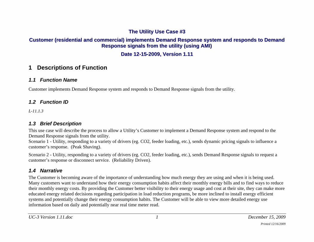
Customer Energy Management System
System CEMS. Customer owned premise system which interfaces with the Home Area Network and the AMI Premise Interface to provide services for load management and distributed generation. Additionally, may provide the Customer ability to control Customer owned equipment independent of the AMI.
Customer Person Residential or commercial energy user that has a contract with the utility to receive electrical service from the utility and have an AMI meter installed. The Customer participates in programs provided by the utility including pricing events, load control or distributed generation. Receives pricing and event information from the AMI. Pre-programs responses to events into their load controllers). Needs to reduce their load throughout the event to reduce energy costs or receive financial benefit.
AMI Renewable Energy Credit Meter
Device AMI REC Meter. AMI Renewable Energy Credit Meter is a revenue grade meter used to measure the energy supplied by Customer owned Distributed Generation. The AMI Renewable Energy Credit Meter information is recorded and forwarded to the PV Program Manager. Advanced electric revenue meter capable of two-way communications with the utility. A device that serves as a gateway between the utility, Customer site, and load controllers of the Customer. The meter measures, records, displays, and transmits data such as energy usage, generation, text messages, event logs, etc. to authorized systems (i.e., the AMI Network Management System) and provides other advanced utility functions.
Customer Control Equipment
Device Switches loads on or off or reduces load in response to events communicated by the AMI system (Meter). Needs to follow the preprogrammed rules. E.g. smart thermostat.
UC-3 Version 1.11.doc 4 December 15, 2009 Printed 12/16/2009
Grouping (Community) , Group Description
Actors Functioning from Customer’s Premises. Actors that perform their specific functions from the customer’s premises.
Actor Name Actor Type (person, device, system Actor Description etc.)
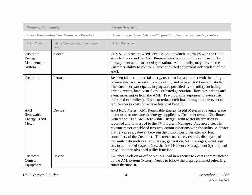
(residential) Customer Display Device
Device Display device that receives energy and event information from the AMI and presents it to the Customer.
AMI Net/Billing Meter
Device AMI Net/Billing Meter is a bi-directional revenue grade meter used to measure energy supplied by the Distributed Generation or used by the Customer. Advanced electric revenue meter capable of two-way communications with the utility. A device that serves as a gateway between the utility, Customer site, and load controllers of the Customer. The meter measures, records, displays, and transmits data such as energy usage, generation, text messages, event logs, etc. to authorized systems (i.e., the AMI Network Management System) and provides other advanced utility functions.
AMI Meter Device Advanced electric revenue meter capable of two-way communications with the utility. A device that serves as a gateway between the utility, Customer site, and Customer load controllers. The meter measures, records, displays, and transmits data such as energy usage, generation, text messages, event logs, etc. to authorized systems (i.e., the AMI Network Management System) and provides other advanced utility functions.
AMI Premise Interface
System The AMI Premise Interface is one of the communications radios that could be “under glass” of the AMI Meter. (There are two radios built in to the AMI Meter. One is for the AMI System and is a longer range radio. The other is for the AMI Premise Interface and it has a smaller range.) This is the communication resource to the Inverter and the Home Area Network (if available).
UC-3 Version 1.11.doc 5 December 15, 2009 Printed 12/16/2009

Grouping (Community) , Group Description
Actors Functioning from Customer’s Premises. Actors that perform their specific functions from the customer’s premises.
Actor Name Actor Type (person, device, system Actor Description etc.)
Customer Inverter
Device Equipment at the Customer site belonging to the Customer that can be used for control of DG real and reactive power output.
Customer Predefined Profile
System The Customer completes a profile upon installation that will determine how the Customer premise will function under different circumstances (pricing, etc.). This profile is programmed into the Customer Energy Management System.
Replicate this table for each logic group.
Grouping (Community) , Group Description
The Utility Actors. Actors that perform their specific functions as a part of the Utility.
Actor Name Actor Type (person, device, system etc.)
Actor Description
The Utility System Host utility. Meter Data Management System
System MDMS. System that gathers, validates, estimates and permits editing of meter data such as energy usage, generation, and meter logs. It stores this data for a limited amount of time before it goes to a data warehouse (Meter Data Archive), and makes this data available to authorized systems and authorized personnel.
Distributed Resource Availability and Control System
System DRAACS. System and subsystems responsible for maintaining an estimate, with a known precision, of how much resource is available for dispatch. Distributed Resource Availability and Control System is also responsible for accepting requests for blocks of energy and/or capacity and implementing that request by issuing load control requests. Distributed Resource
UC-3 Version 1.11.doc 6 December 15, 2009 Printed 12/16/2009

Grouping (Community) , Group Description
The Utility Actors. Actors that perform their specific functions as a part of the Utility.
Actor Name Actor Type (person, device, system Actor Description etc.)
Availability and Control System contains an optimization function that can determine the optimal Customer set to request curtailment from based upon a variety of factors/parameters, including the size and location of the desired Demand Response (DR) resource. Distributed Resource Availability and Control System is expected to track the "as implemented" response to load control requests and issue additional load reduction requests to selected Customer sets until authorized load reduction target is met. Distributed Resource Availability and Control System uses measured responses to load demand requests to refine its internal model. Note: Any Distributed Resource Availability and Control System in use today may be parts of other systems being used. No platform exists to bring it into an operational tool today.
Grid Control Center
System GCC. The Grid Control Center controls grid operations through the Energy Management System, SCADA and Distribution Management System in the control area. The Grid Control Center will communicate to grid operators to ensure grid reliability and also sends signals.
Customer Information System
System CIS. Maintains Customer contact information, calculates and formats Customer bills, receives, and applies payments for individual accounts. The system is responsible for storing Customer information such as site data, meter number, rates, and program participation.
Customer Service Representative
Person CSR. Staff employed by the utility who respond to Customer complaints, to outage notifications, or to Customer requests to activate, modify and/or terminate delivery of service. Customer Service Representatives also enroll a Customer in utility sponsored programs and answer questions related to the energy consumption and cost data of the Customer. Many off-cycle reading,
UC-3 Version 1.11.doc 7 December 15, 2009 Printed 12/16/2009

Grouping (Community) , Group Description
The Utility Actors. Actors that perform their specific functions as a part of the Utility.
Actor Name Actor Type (person, device, system Actor Description etc.)
billing, work orders and diagnostics requests are initiated by the Customer Service Representative in response to Customer contact.
AMI Network Management System
System AMI NMS. AMI Network Management System is the utility back office system that is responsible for remote two-way communications with the AMI Meters to retrieve data and execute commands. The AMI Network Management System has the responsibility to balance load on the communications network resulting from scheduled meter reads and to retry meters when communications fail. AMI Network Management System is the component responsible for monitoring the health of the AMI system, managing and implementing remote firmware updates, configuration changes, provisioning functions, control and diagnostics.
Distribution Management System
System DMS. A system that integrates the functions of SCADA, outage management, work management, distribution load management, reactive control, and asset management into a single console and set of applications.
AMI System Advanced Metering Infrastructure. Advanced electric revenue metering system capable of two-way communications between the Customer and the utility. A device that serves as a gateway (AMI Premise Interface) between the utility, Customer site, and load controllers of the Customer. The meter measures, records, displays, and transmits data such as energy usage, generation, text messages, event logs, etc. to authorized systems (i.e., the AMI Network Management System) and provides other advanced utility functions..
Wholesale Power Group
Person WPG. Takes all resources available and determines optimum generation mix on economic basis
UC-3 Version 1.11.doc 8 December 15, 2009 Printed 12/16/2009

Grouping (Community) , Group Description
The Utility Actors. Actors that perform their specific functions as a part of the Utility.
Actor Name Actor Type (person, device, system Actor Description etc.)
Power Operations
Person PO. Initiates dynamic pricing data or demand response events to mitigate transmission reliability requirements
Distribution Operations
Person DO. Operating over the distribution system, using SCADA and Distribution Management System to make decisions concerning the distribution grid. Initiates dynamic pricing data or demand response events to mitigate distribution reliability and voltage profile requirements.
Price Origination Group
System Develop the rules that translate the resource costs and reliability inputs into dynamic pricing and demand response signals for the Customer
Energy Management System
System EMS. The Energy Management System controls grid operations in the control area. The Energy Management System will communicate to substation RTUs to ensure grid reliability.
1.6 Information exchanged Describe any information exchanged in this template.
Information Object Name Information Object Description
Wholesale Power Group loading and additional pricing information
System loading information and additional information that may affect the pricing signal.
UC-3 Version 1.11.doc 9 December 15, 2009 Printed 12/16/2009

Information Object Name Information Object Description
Distribution Management System loading and additional pricing information
System loading information and additional information that may affect the pricing signal.
Wholesale Power Group and Distribution Management System loading and additional pricing information
A combination of the system loading information and additional information that may affect the pricing signal sent from the Wholesale Power Group and the Distribution Management System.
Current Dynamic Pricing Signal Pricing Signal calculated when the Price Origination Group enters the loading and additional pricing information into the Dynamic Pricing Signal Application.
Current Dynamic Pricing Signal and the Customer Predefined Profile
Calculated pricing signal from the Dynamic Pricing Signal Application that is compared to the Customer Predefined Profile. This comparison is made automatically and will determine how the Customer Energy Management System and the affected premises (controlled premise devices) will respond.
AMI Net/Billing Meter Read Request
A request for an AMI Net/Billing Meter Read.
AMI Net/Billing Meter Data Meter data for a specific AMI Net/Billing Meter. This data includes voltage, current, load and power quality parameters.
Updated System and System Condition Data
Updated field equipment status, system or area load, voltage parameters, power quality and outages.
Demand Response Event Based on Reliability
Demand Response Event called to maintain system reliability.
Demand Response Selected Customer Listing for the Demand Response Event Notification
Selected set of customers chosen to meet the requirements of the Demand Response Event.
Compares the Demand Response Selected Customer Listing for the
The Customers selected to meet the requirements of the Demand Response Event will have the event parameters compared to their Customer Predefined Profile. This comparison is made automatically
UC-3 Version 1.11.doc 10 December 15, 2009 Printed 12/16/2009

Information Object Name Information Object Description
Demand Response Event Notification with the Customer Predefined Profile
and will determine how the Customer Energy Management System and the affected premises (controlled premise devices) will respond.
Acknowledgement of Demand Response Event Notification
The Customer will be sent a notification of the Demand Response Event on the Customer Display. The Customer can acknowledge that event by pushing the Acknowledge Button on the Customer Display. The Customer isn’t required to acknowledge the event.
Demand Response Override Function
When the Customer chooses to “Override” a selected Demand Response Event, they will be required to acknowledge the event on their Customer Display by pushing the “Acknowledge” button and entering the correct “Override Code” onto the Customer Display. When the Customer Display receives the correct “Override Code” it will send a “Demand Response Override Function” to the Customer Energy Management System, which will allow the controlled premise devices to act accordingly.
Demand Response Override Command
After a Customer chooses to “Override” a specific Demand Response Event, the Customer Energy Management System receives a “Demand Response Override Function” from the Customer Display. The Customer Energy Management System reads this “Demand Response Override Function” and sends out a “Demand Response Override Command” to the controlled devices in the premise. The controlled devices will receive the “Demand Response Override Command” and respond accordingly.
Override Acknowledgement The “Override Acknowledgement” is developed when the Customer Energy Management System receives verification from the controlled devices in the premise that they have responded accordingly to the “Demand Response Override Command”. The Customer Energy Management System sends the “Override Acknowledgement” signal back to the Distributed Resource Availability and Control System and the Meter Data Management System to allow the system to know which Customers decided to “Override” the Demand Response Event and to allow for the system to verify if enough load was affected to meet the needs of the Demand Response Event.
Equipment Status Notification During normal operation (not during “Override”) the Customer Energy Management System will send and “Equipment Status Notification” to the Distributed Resource Availability and Control System and the Meter Data Management System to allow the system to know which Customers responded the Demand Response Event and to allow for the system to verify if enough load was
UC-3 Version 1.11.doc 11 December 15, 2009 Printed 12/16/2009
Information Object Name Information Object Description
affected to meet the needs of the Demand Response Event.
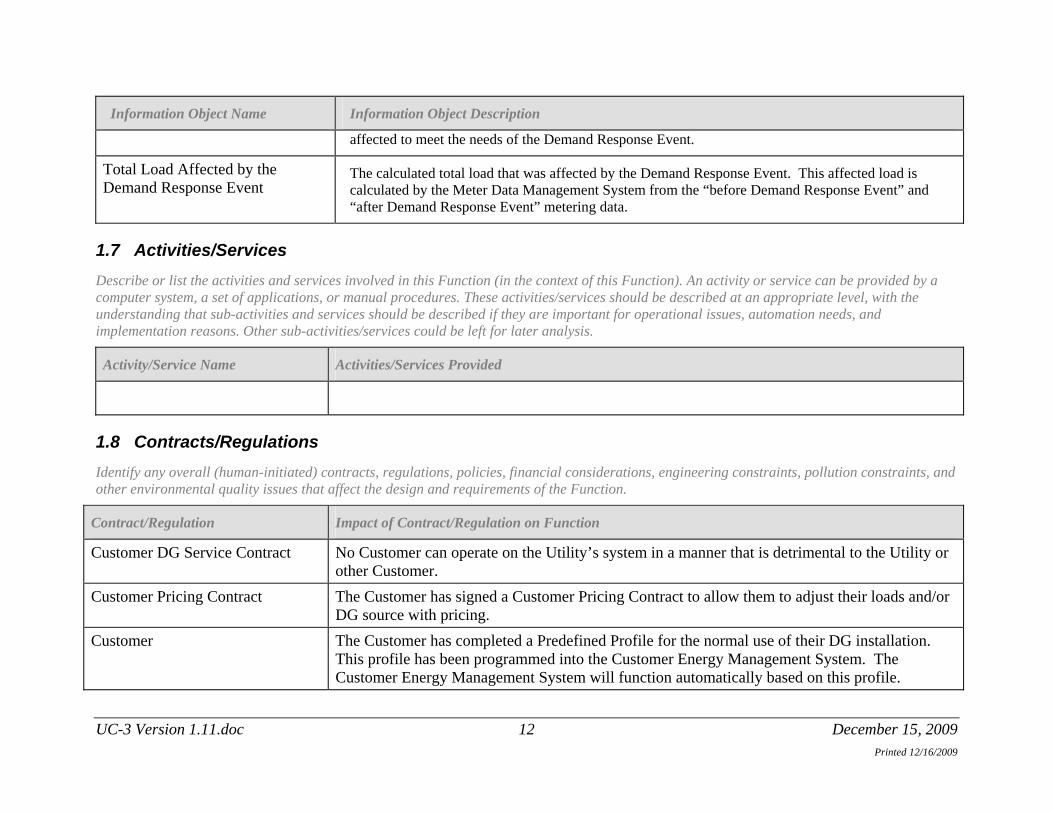
Total Load Affected by the Demand Response Event
The calculated total load that was affected by the Demand Response Event. This affected load is calculated by the Meter Data Management System from the “before Demand Response Event” and “after Demand Response Event” metering data.
1.7 Activities/Services Describe or list the activities and services involved in this Function (in the context of this Function). An activity or service can be provided by a computer system, a set of applications, or manual procedures. These activities/services should be described at an appropriate level, with the understanding that sub-activities and services should be described if they are important for operational issues, automation needs, and implementation reasons. Other sub-activities/services could be left for later analysis.
Activity/Service Name Activities/Services Provided
1.8 Contracts/Regulations Identify any overall (human-initiated) contracts, regulations, policies, financial considerations, engineering constraints, pollution constraints, and other environmental quality issues that affect the design and requirements of the Function.
Contract/Regulation Impact of Contract/Regulation on Function
Customer DG Service Contract No Customer can operate on the Utility’s system in a manner that is detrimental to the Utility or other Customer.
Customer Pricing Contract The Customer has signed a Customer Pricing Contract to allow them to adjust their loads and/or DG source with pricing.
Customer The Customer has completed a Predefined Profile for the normal use of their DG installation. This profile has been programmed into the Customer Energy Management System. The Customer Energy Management System will function automatically based on this profile.
UC-3 Version 1.11.doc 12 December 15, 2009 Printed 12/16/2009

Policy
From Actor
May Shall Not
Shall Description (verb) To Actor
Constraint Type Description Applies to
2 Step by Step Analysis of Function
2.1 Steps to implement function – Scenario 1 – sending dynamic pricing signals Scenario 1 – sending dynamic pricing signals
2.1.1 Preconditions and Assumptions Describe conditions that must exist prior to the initiation of the Function, such as prior state of the actors and activities
Identify any assumptions, such as what systems already exist, what contractual relations exist, and what configurations of systems are probably in place
Identify any initial states of information exchanged in the steps in the next section. For example, if a purchase order is exchanged in an activity, its precondition to the activity might be ‘filled in but unapproved’.
Actor/System/Information/Contract Preconditions or Assumptions
Customer The Customer has enrolled in dynamic pricing tariff
Customer Customer has enrolled in utility demand response program (alternate scenario)
UC-3 Version 1.11.doc 13 December 15, 2009 Printed 12/16/2009

Actor/System/Information/Contract Preconditions or Assumptions
Customer Customer has selected a method for Pricing/Demand Response event notification signals
The Utility Wholesale Power Group gets system load feedback via the Distribution Management System
The Utility AMI system is installed
Customer The Customer has completed a Predefined Profile for the normal use of their DG installation. This profile has been programmed into the Customer Energy Management System. The Customer Energy Management System will function automatically based on this profile.
2.1.2 Steps Describe the normal sequence of events, focusing on steps that identify new types of information or new information exchanges or new interface issues to address. Should the sequence require detailed steps that are also used by other functions, consider creating a new “sub” function, then referring to that “subroutine” in this function. Remember that the focus should be less on the algorithms of the applications and more on the interactions and information flows between “entities”, e.g. people, systems, applications, data bases, etc. There should be a direct link between the narrative and these steps.
The numbering of the sequence steps conveys the order and concurrency and iteration of the steps occur. Using a Dewey Decimal scheme, each level of nested procedure call is separated by a dot ‘.’. Within a level, the sequence number comprises an optional letter and an integer number. The letter specifies a concurrent sequence within the next higher level; all letter sequences are concurrent with other letter sequences. The number specifies the sequencing of messages in a given letter sequence. The absence of a letter is treated as a default 'main sequence' in parallel with the lettered sequences.
Sequence 1: 1.1 - Do step 1 1.2A.1 - In parallel to activity 2 B do step 1
1.2A.2 - In parallel to activity 2 B do step 2 1.2B.1 - In parallel to activity 2 A do step 1 1.2B.2 - In parallel to activity 2 A do step 2 1.3 - Do step 3
1.3.1 - nested step 3.1
UC-3 Version 1.11.doc 14 December 15, 2009 Printed 12/16/2009
1.3.2 - nested step 3.2
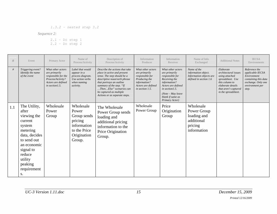
Sequence 2: 2.1 - Do step 1 2.2 – Do step 2
# Event Primary Actor Name of Process/Activity
Description of Process/Activity
Information Producer
Information Receiver
Name of Info Exchanged Additional Notes IECSA
Environments
# Triggering event? Identify the name of the event
What other actors are primarily responsible for the Process/Activity? Actors are defined in section1.5.
Label that would appear in a process diagram. Use action verbs when naming activity.
Describe the actions that take place in active and present tense. The step should be a descriptive noun/verb phrase that portrays an outline summary of the step. “If …Then…Else” scenarios can be captured as multiple Actions or as separate steps.
What other actors are primarily responsible for Producing the information? Actors are defined in section 1.5.
What other actors are primarily responsible for Receiving the information? Actors are defined in section1.5.
(Note – May leave blank if same as Primary Actor)
Name of the information object. Information objects are defined in section 1.6
Elaborate architectural issues using attached spreadsheet. Use this column to elaborate details that aren’t captured in the spreadsheet.
Reference the applicable IECSA Environment containing this data exchange. Only one environment per step.
1.1 The Utility, after viewing the current system metering data, decides to send out an economic signal to reduce utility peaking requirements.
Wholesale Power Group
Wholesale Power Group sends pricing information to the Price Origination Group.
The Wholesale Power Group sends loading and additional pricing information to the Price Origination Group.
Wholesale Power Group
Price Origination Group
Wholesale Power Group loading and additional pricing information
UC-3 Version 1.11.doc 15 December 15, 2009 Printed 12/16/2009

Name of Description of Information Information Name of Info IECSA # Event Primary Actor Additional Notes
Printed 12/16/2009
Process/Activity Process/Activity Producer Receiver Exchanged Environments
1.1.1
The Utility, after viewing the current system metering data, decides to send out an economic signal to encourage the Customer to react in a certain way.
Distribution Management System
Distribution Management System sends pricing information to the Price Origination Group
The Distribution Management System sends loading and additional pricing information to the Price Origination Group.
Distribution Management System
Price Origination Group
Distribution Management System loading and additional pricing information
1.1.2
The Price Origination Group enters information into the Dynamic Pricing Signal Application
Price Origination Group
The Price Origination Group enters information into the Dynamic Pricing Signal Application.
The Price Origination Group enters the loading and additional pricing information into the Dynamic Pricing Signal Application.
Price Origination Group
Dynamic Pricing Signal Application
Wholesale Power Group and Distribution Management System loading and additional pricing information
UC-3 Version 1.11.doc 16 December 15, 2009

Name of Description of Information Information Name of Info IECSA # Event Primary Actor Additional Notes
Printed 12/16/2009
Process/Activity Process/Activity Producer Receiver Exchanged Environments
1.2 The Dynamic Pricing Signal Application calculates the Current Dynamic Pricing Signal.
Dynamic Pricing Signal Application
The Dynamic Pricing Signal Application calculates the Current Dynamic Pricing Signal.
The Dynamic Pricing Signal Application calculates the Current Dynamic Pricing Signal.
Dynamic Pricing Signal Application
Dynamic Pricing Signal Application
Current Dynamic Pricing Signal
1.2.1A
The Dynamic Pricing Signal Application delivers the Current Dynamic Pricing Signal to the Price Origination Group.
Dynamic Pricing Signal Application
The Dynamic Pricing Signal Application delivers the Current Dynamic Pricing Signal to the Price Origination Group.
The Dynamic Pricing Signal Application delivers the Current Dynamic Pricing Signal to the Price Origination Group.
Dynamic Pricing Signal Application
Price Origination Group
Current Dynamic Pricing Signal
UC-3 Version 1.11.doc 17 December 15, 2009

Name of Description of Information Information Name of Info IECSA # Event Primary Actor Additional Notes
Printed 12/16/2009
Process/Activity Process/Activity Producer Receiver Exchanged Environments
1.2.1B
The Dynamic Pricing Signal Application delivers the Current Dynamic Pricing Signal to the Meter Data Management System.
Dynamic Pricing Signal Application
The Dynamic Pricing Signal Application delivers the Current Dynamic Pricing Signal to the Meter Data Management System.
The Dynamic Pricing Signal Application delivers the Current Dynamic Pricing Signal to the Meter Data Management System
Dynamic Pricing Signal Application
Meter Data Management System
Current Dynamic Pricing Signal
1.2.1C
The Dynamic Pricing Signal Application delivers the Current Dynamic Pricing Signal to the Customer Information System.
Dynamic Pricing Signal Application
The Dynamic Pricing Signal Application delivers the Current Dynamic Pricing Signal to the Customer Information System.
The Dynamic Pricing Signal Application delivers the Current Dynamic Pricing Signal to the Customer Information System.
Dynamic Pricing Signal Application
Customer Information System
Current Dynamic Pricing Signal
UC-3 Version 1.11.doc 18 December 15, 2009

Name of Description of Information Information Name of Info IECSA # Event Primary Actor Additional Notes
Printed 12/16/2009
Process/Activity Process/Activity Producer Receiver Exchanged Environments
1.2.1D
The Dynamic Pricing Signal Application delivers the Current Dynamic Pricing Signal to the AMI Network Management System.
Dynamic Pricing Signal Application
The Dynamic Pricing Signal Application delivers the Current Dynamic Pricing Signal to the AMI Network Management System.
The Dynamic Pricing Signal Application delivers the Current Dynamic Pricing Signal to the AMI Network Management System.
Dynamic Pricing Signal Application
AMI Network Management System
Current Dynamic Pricing Signal
1.2.1D.1
The AMI Network Management System delivers the Current Dynamic Pricing Signal to the AMI Premise Interface.
AMI Network Management System
The AMI Network Management System delivers the Current Dynamic Pricing Signal to the AMI Premise Interface.
The AMI Network Management System delivers the Current Dynamic Pricing Signal to the AMI Premise Interface via the AMI Infrastructure.
AMI Network Management System
AMI Premise Interface
Current Dynamic Pricing Signal
UC-3 Version 1.11.doc 19 December 15, 2009

Name of Description of Information Information Name of Info IECSA # Event Primary Actor Additional Notes
Printed 12/16/2009
Process/Activity Process/Activity Producer Receiver Exchanged Environments
1.2.1D.2
The AMI Premise Interface delivers the Current Dynamic Pricing Signal to the Customer Display.
AMI Premise Interface
The AMI Premise Interface delivers the Current Dynamic Pricing Signal to the Customer Display.
The AMI Premise Interface sends the Current Dynamic Pricing Signal to the Customer Display.
AMI Premise Interface
Customer Display Device
Current Dynamic Pricing Signal
1.2.1D.3
The AMI Premise Interface delivers the Current Dynamic Pricing Signal to the Customer Energy Management System.
AMI Premise Interface
The AMI Premise Interface delivers the Current Dynamic Pricing Signal to the Customer Energy Management System.
The AMI Premise Interface sends the Current Dynamic Pricing Signal to the Customer Energy Management System.
AMI Premise Interface
Customer Energy Management System
Current Dynamic Pricing Signal
UC-3 Version 1.11.doc 20 December 15, 2009
Name of Description of Information Information Name of Info IECSA # Event Primary Actor Additional Notes
Printed 12/16/2009
Process/Activity Process/Activity Producer Receiver Exchanged Environments
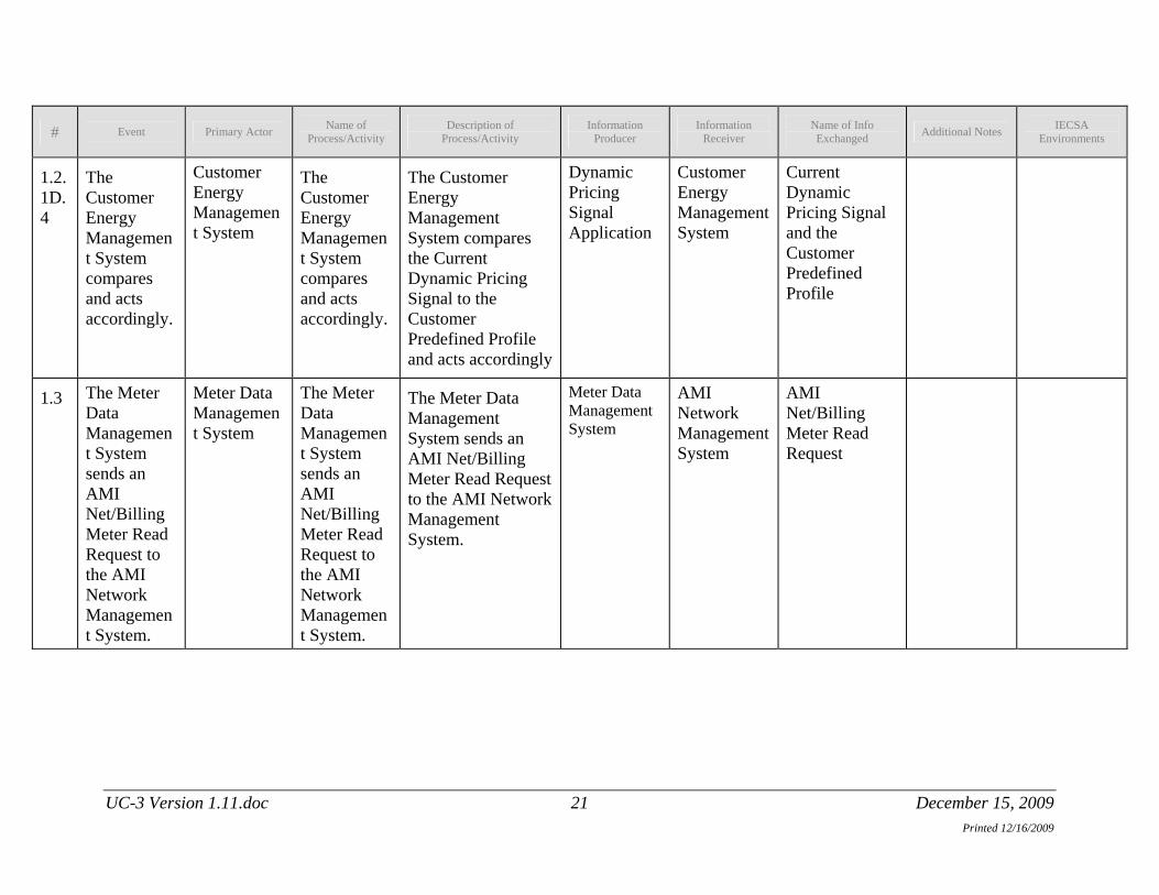
1.2.1D.4
The Customer Energy Management System compares and acts accordingly.
Customer Energy Management System
The Customer Energy Management System compares and acts accordingly.
The Customer Energy Management System compares the Current Dynamic Pricing Signal to the Customer Predefined Profile and acts accordingly
Dynamic Pricing Signal Application
Customer Energy Management System
Current Dynamic Pricing Signal and the Customer Predefined Profile
1.3 The Meter Data Management System sends an AMI Net/Billing Meter Read Request to the AMI Network Management System.
Meter Data Management System
The Meter Data Management System sends an AMI Net/Billing Meter Read Request to the AMI Network Management System.
The Meter Data Management System sends an AMI Net/Billing Meter Read Request to the AMI Network Management System.
Meter Data Management System
AMI Network Management System
AMI Net/Billing Meter Read Request
UC-3 Version 1.11.doc 21 December 15, 2009
Name of Description of Information Information Name of Info IECSA # Event Primary Actor Additional Notes
Printed 12/16/2009
Process/Activity Process/Activity Producer Receiver Exchanged Environments
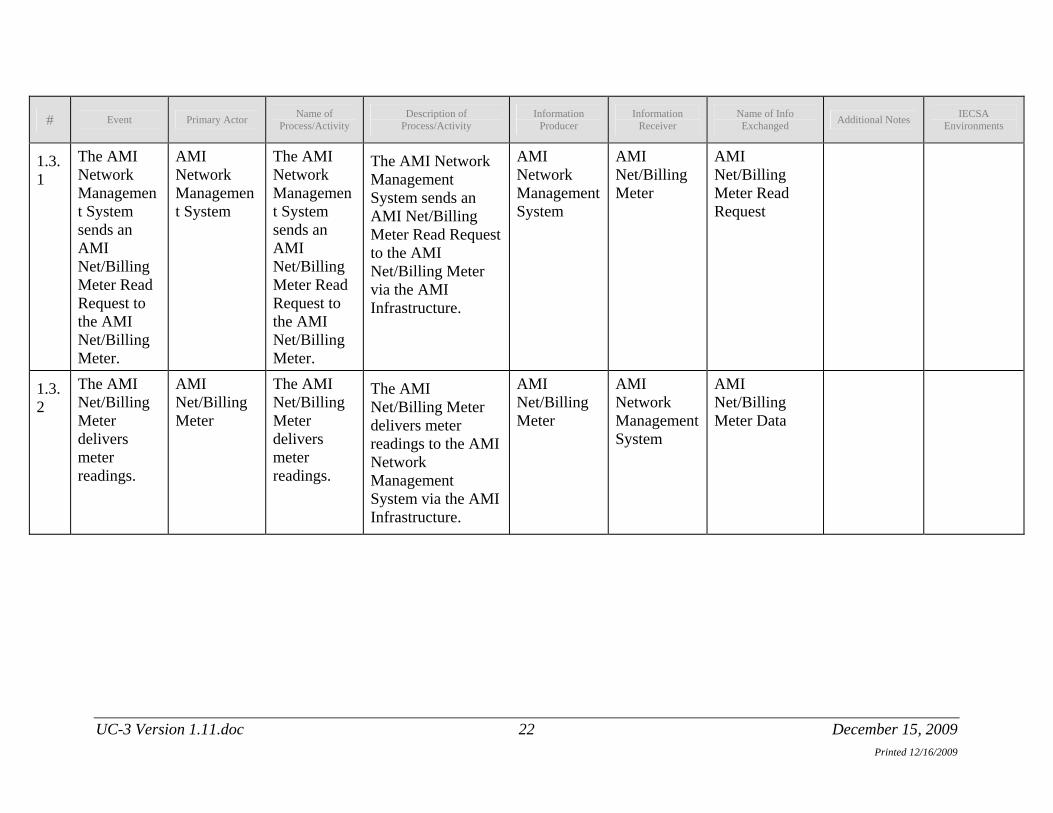
1.3.1
The AMI Network Management System sends an AMI Net/Billing Meter Read Request to the AMI Net/Billing Meter.
AMI Network Management System
The AMI Network Management System sends an AMI Net/Billing Meter Read Request to the AMI Net/Billing Meter.
The AMI Network Management System sends an AMI Net/Billing Meter Read Request to the AMI Net/Billing Meter via the AMI Infrastructure.
AMI Network Management System
AMI Net/Billing Meter
AMI Net/Billing Meter Read Request
1.3.2
The AMI Net/Billing Meter delivers meter readings.
AMI Net/Billing Meter
The AMI Net/Billing Meter delivers meter readings.
The AMI Net/Billing Meter delivers meter readings to the AMI Network Management System via the AMI Infrastructure.
AMI Net/Billing Meter
AMI Network Management System
AMI Net/Billing Meter Data
UC-3 Version 1.11.doc 22 December 15, 2009
Name of Description of Information Information Name of Info IECSA # Event Primary Actor Additional Notes
Printed 12/16/2009
Process/Activity Process/Activity Producer Receiver Exchanged Environments
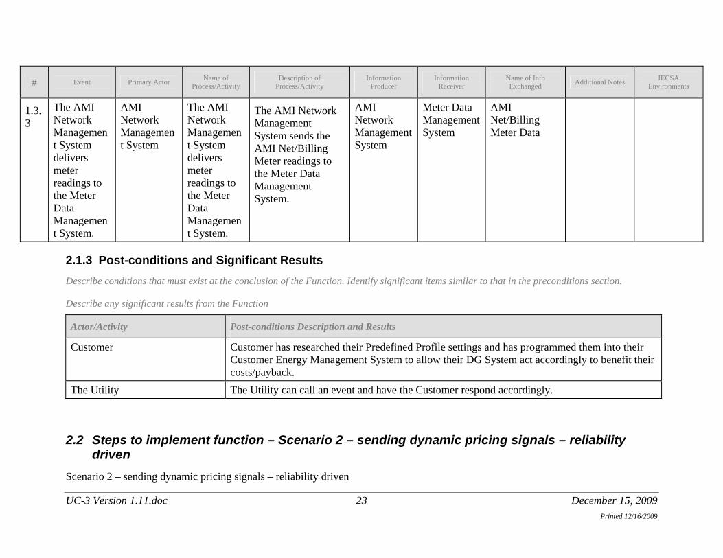
1.3.3
The AMI Network Management System delivers meter readings to the Meter Data Management System.
AMI Network Management System
The AMI Network Management System delivers meter readings to the Meter Data Management System.
The AMI Network Management System sends the AMI Net/Billing Meter readings to the Meter Data Management System.
AMI Network Management System
Meter Data Management System
AMI Net/Billing Meter Data
2.1.3 Post-conditions and Significant Results Describe conditions that must exist at the conclusion of the Function. Identify significant items similar to that in the preconditions section.
Describe any significant results from the Function
Actor/Activity Post-conditions Description and Results
Customer Customer has researched their Predefined Profile settings and has programmed them into their Customer Energy Management System to allow their DG System act accordingly to benefit their costs/payback.
The Utility The Utility can call an event and have the Customer respond accordingly.
2.2 Steps to implement function – Scenario 2 – sending dynamic pricing signals – reliability driven
Scenario 2 – sending dynamic pricing signals – reliability driven
UC-3 Version 1.11.doc 23 December 15, 2009
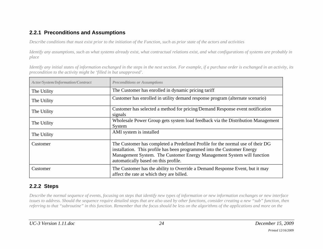
2.2.1 Preconditions and Assumptions Describe conditions that must exist prior to the initiation of the Function, such as prior state of the actors and activities
Identify any assumptions, such as what systems already exist, what contractual relations exist, and what configurations of systems are probably in place
Identify any initial states of information exchanged in the steps in the next section. For example, if a purchase order is exchanged in an activity, its precondition to the activity might be ‘filled in but unapproved’.
Actor/System/Information/Contract Preconditions or Assumptions
The Utility The Customer has enrolled in dynamic pricing tariff
The Utility Customer has enrolled in utility demand response program (alternate scenario)
The Utility Customer has selected a method for pricing/Demand Response event notification signals
The Utility Wholesale Power Group gets system load feedback via the Distribution Management System
The Utility AMI system is installed
Customer The Customer has completed a Predefined Profile for the normal use of their DG installation. This profile has been programmed into the Customer Energy Management System. The Customer Energy Management System will function automatically based on this profile.
Customer The Customer has the ability to Override a Demand Response Event, but it may affect the rate at which they are billed.
2.2.2 Steps Describe the normal sequence of events, focusing on steps that identify new types of information or new information exchanges or new interface issues to address. Should the sequence require detailed steps that are also used by other functions, consider creating a new “sub” function, then referring to that “subroutine” in this function. Remember that the focus should be less on the algorithms of the applications and more on the
UC-3 Version 1.11.doc 24 December 15, 2009 Printed 12/16/2009
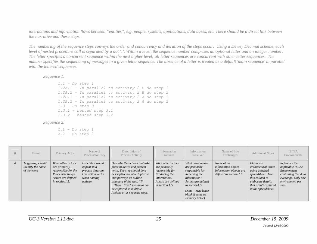
interactions and information flows between “entities”, e.g. people, systems, applications, data bases, etc. There should be a direct link between the narrative and these steps.
The numbering of the sequence steps conveys the order and concurrency and iteration of the steps occur. Using a Dewey Decimal scheme, each level of nested procedure call is separated by a dot ‘.’. Within a level, the sequence number comprises an optional letter and an integer number. The letter specifies a concurrent sequence within the next higher level; all letter sequences are concurrent with other letter sequences. The number specifies the sequencing of messages in a given letter sequence. The absence of a letter is treated as a default 'main sequence' in parallel with the lettered sequences.
Sequence 1: 1.1 - Do step 1 1.2A.1 - In parallel to activity 2 B do step 1
1.2A.2 - In parallel to activity 2 B do step 2 1.2B.1 - In parallel to activity 2 A do step 1 1.2B.2 - In parallel to activity 2 A do step 2 1.3 - Do step 3
1.3.1 - nested step 3.1 1.3.2 - nested step 3.2
Sequence 2: 2.1 - Do step 1 2.2 – Do step 2
# Event Primary Actor Name of Process/Activity
Description of Process/Activity
Information Producer
Information Receiver
Name of Info Exchanged Additional Notes IECSA
Environments
# Triggering event? Identify the name of the event
What other actors are primarily responsible for the Process/Activity? Actors are defined in section1.5.
Label that would appear in a process diagram. Use action verbs when naming activity.
Describe the actions that take place in active and present tense. The step should be a descriptive noun/verb phrase that portrays an outline summary of the step. “If …Then…Else” scenarios can be captured as multiple Actions or as separate steps.
What other actors are primarily responsible for Producing the information? Actors are defined in section 1.5.
What other actors are primarily responsible for Receiving the information? Actors are defined in section1.5.
(Note – May leave blank if same as Primary Actor)
Name of the information object. Information objects are defined in section 1.6
Elaborate architectural issues using attached spreadsheet. Use this column to elaborate details that aren’t captured in the spreadsheet.
Reference the applicable IECSA Environment containing this data exchange. Only one environment per step.
UC-3 Version 1.11.doc 25 December 15, 2009 Printed 12/16/2009

Name of Description of Information Information Name of Info IECSA # Event Primary Actor Additional Notes
Printed 12/16/2009
Process/Activity Process/Activity Producer Receiver Exchanged Environments
2.1 The Utility decides, because of reliability concerns, to issue a Demand Response Event Notification.
Distribution Management System
Distribution Management System sends system condition data to the Distribution Operations.
Distribution Management System updates system data and sends the system condition data to the Distribution Operations.
Distribution Management System
Distribution Operations
Updated System and System Condition Data
2.1.1
The Utility decides, because of reliability concerns, to issue a Demand Response Event Notification.
Distribution Operations
Distribution Operations review the system condition data.
Distribution Operations review the system condition data and determine that a Demand Response event is required for system reliability.
Distribution Management System
Distribution Operations
Updated System and System Condition Data
UC-3 Version 1.11.doc 26 December 15, 2009
Name of Description of Information Information Name of Info IECSA # Event Primary Actor Additional Notes
Printed 12/16/2009
Process/Activity Process/Activity Producer Receiver Exchanged Environments
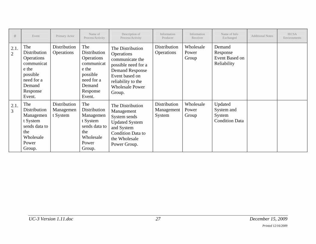
2.1.2
The Distribution Operations communicate the possible need for a Demand Response Event.
Distribution Operations
The Distribution Operations communicate the possible need for a Demand Response Event.
The Distribution Operations communicate the possible need for a Demand Response Event based on reliability to the Wholesale Power Group.
Distribution Operations
Wholesale Power Group
Demand Response Event Based on Reliability
2.1.3
The Distribution Management System sends data to the Wholesale Power Group.
Distribution Management System
The Distribution Management System sends data to the Wholesale Power Group.
The Distribution Management System sends Updated System and System Condition Data to the Wholesale Power Group.
Distribution Management System
Wholesale Power Group
Updated System and System Condition Data
UC-3 Version 1.11.doc 27 December 15, 2009
Name of Description of Information Information Name of Info IECSA # Event Primary Actor Additional Notes
Printed 12/16/2009
Process/Activity Process/Activity Producer Receiver Exchanged Environments
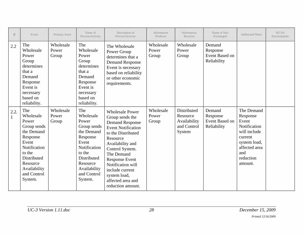
2.2 The Wholesale Power Group determines that a Demand Response Event is necessary based on reliability.
Wholesale Power Group
The Wholesale Power Group determines that a Demand Response Event is necessary based on reliability.
The Wholesale Power Group determines that a Demand Response Event is necessary based on reliability or other economic requirements.
Wholesale Power Group
Wholesale Power Group
Demand Response Event Based on Reliability
2.2.1
The Wholesale Power Group sends the Demand Response Event Notification to the Distributed Resource Availability and Control System.
Wholesale Power Group
The Wholesale Power Group sends the Demand Response Event Notification to the Distributed Resource Availability and Control System.
Wholesale Power Group sends the Demand Response Event Notification to the Distributed Resource Availability and Control System. The Demand Response Event Notification will include current system load, affected area and reduction amount.
Wholesale Power Group
Distributed Resource Availability and Control System
Demand Response Event Based on Reliability
The Demand Response Event Notification will include current system load, affected area and reduction amount.
UC-3 Version 1.11.doc 28 December 15, 2009
Name of Description of Information Information Name of Info IECSA # Event Primary Actor Additional Notes
Printed 12/16/2009
Process/Activity Process/Activity Producer Receiver Exchanged Environments
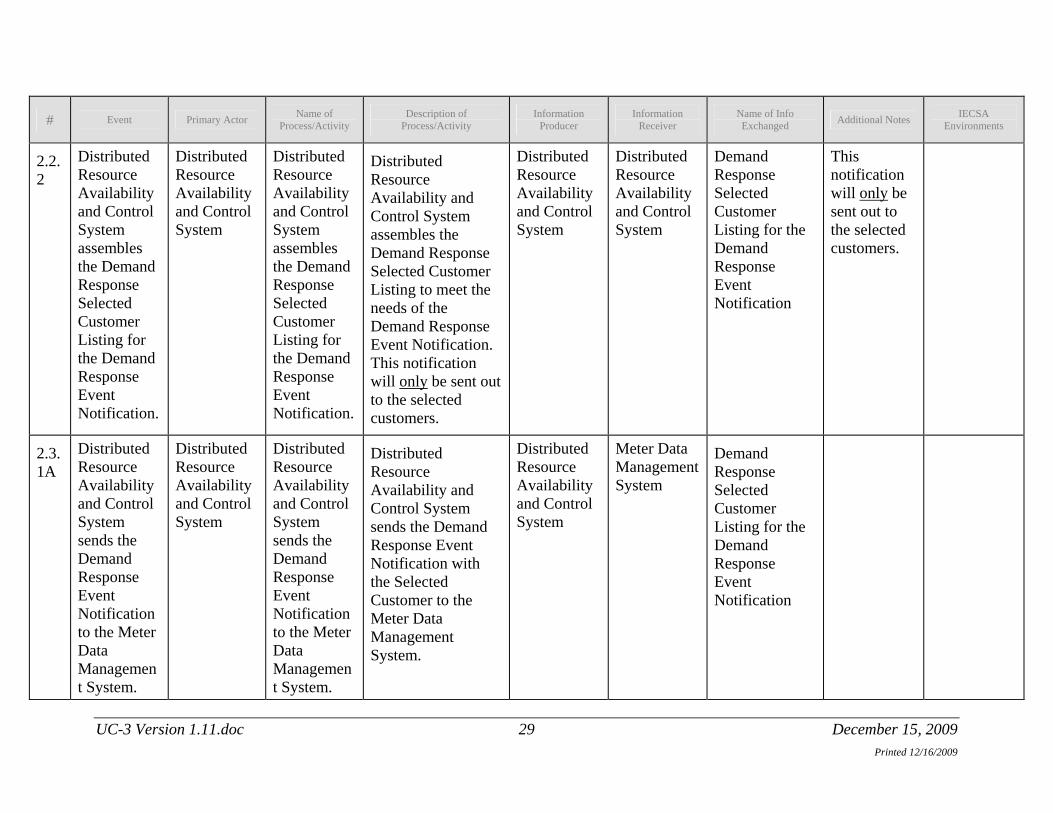
2.2.2
Distributed Resource Availability and Control System assembles the Demand Response Selected Customer Listing for the Demand Response Event Notification.
Distributed Resource Availability and Control System
Distributed Resource Availability and Control System assembles the Demand Response Selected Customer Listing for the Demand Response Event Notification.
Distributed Resource Availability and Control System assembles the Demand Response Selected Customer Listing to meet the needs of the Demand Response Event Notification. This notification will only be sent out to the selected customers.
Distributed Resource Availability and Control System
Distributed Resource Availability and Control System
Demand Response Selected Customer Listing for the Demand Response Event Notification
This notification will only be sent out to the selected customers.
2.3.1A
Distributed Resource Availability and Control System sends the Demand Response Event Notification to the Meter Data Management System.
Distributed Resource Availability and Control System
Distributed Resource Availability and Control System sends the Demand Response Event Notification to the Meter Data Management System.
Distributed Resource Availability and Control System sends the Demand Response Event Notification with the Selected Customer to the Meter Data Management System.
Distributed Resource Availability and Control System
Meter Data Management System
Demand Response Selected Customer Listing for the Demand Response Event Notification
UC-3 Version 1.11.doc 29 December 15, 2009
Name of Description of Information Information Name of Info IECSA # Event Primary Actor Additional Notes
Printed 12/16/2009
Process/Activity Process/Activity Producer Receiver Exchanged Environments
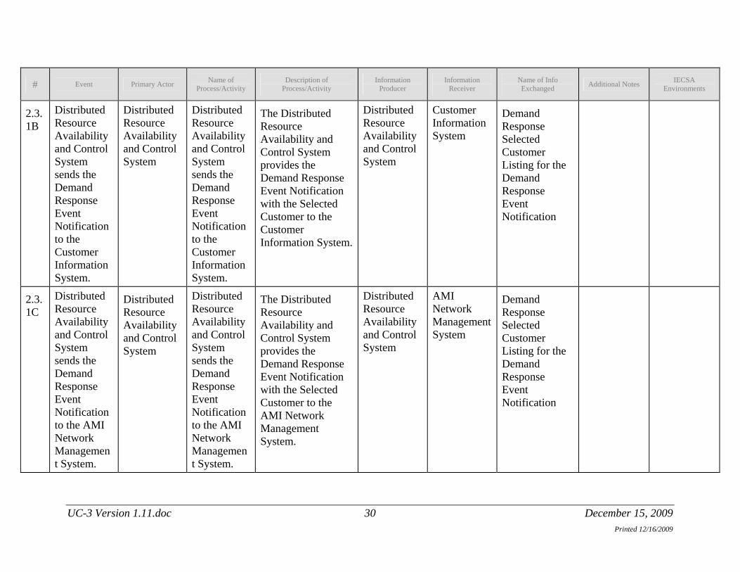
2.3.1B
Distributed Resource Availability and Control System sends the Demand Response Event Notification to the Customer Information System.
Distributed Resource Availability and Control System
Distributed Resource Availability and Control System sends the Demand Response Event Notification to the Customer Information System.
The Distributed Resource Availability and Control System provides the Demand Response Event Notification with the Selected Customer to the Customer Information System.
Distributed Resource Availability and Control System
Customer Information System
Demand Response Selected Customer Listing for the Demand Response Event Notification
2.3.1C
Distributed Resource Availability and Control System sends the Demand Response Event Notification to the AMI Network Management System.
Distributed Resource Availability and Control System
Distributed Resource Availability and Control System sends the Demand Response Event Notification to the AMI Network Management System.
The Distributed Resource Availability and Control System provides the Demand Response Event Notification with the Selected Customer to the AMI Network Management System.
Distributed Resource Availability and Control System
AMI Network Management System
Demand Response Selected Customer Listing for the Demand Response Event Notification
UC-3 Version 1.11.doc 30 December 15, 2009

Name of Description of Information Information Name of Info IECSA # Event Primary Actor Additional Notes
Printed 12/16/2009
Process/Activity Process/Activity Producer Receiver Exchanged Environments
2.3.1C.1
AMI Network Management System sends the Demand Response Event Notification to the AMI Premise Interface.
AMI Network Management System
AMI Network Management System sends the Demand Response Event Notification to the AMI Premise Interface.
The AMI Network Management System sends Demand Response Event Notification with the Selected Customer out to the AMI Premise Interface via the AMI Infrastructure.
AMI Network Management System
AMI Premise Interface
Demand Response Selected Customer Listing for the Demand Response Event Notification
2.3.1C.2A
AMI Premise Interface sends the Demand Response Event Notification to the Customer Energy Management System.
AMI Premise Interface
AMI Premise Interface sends the Demand Response Event Notification to the Customer Energy Management System.
The AMI Premise Interface delivers the Demand Response Event Notification with the Selected Customer to the selected customer’s Customer Energy Management System.
AMI Premise Interface
Customer Energy Management System
Demand Response Selected Customer Listing for the Demand Response Event Notification
UC-3 Version 1.11.doc 31 December 15, 2009

Name of Description of Information Information Name of Info IECSA # Event Primary Actor Additional Notes
Printed 12/16/2009
Process/Activity Process/Activity Producer Receiver Exchanged Environments
2.3.1C.2B
AMI Premise Interface sends the Demand Response Event Notification to the Customer Display.
AMI Premise Interface
AMI Premise Interface sends the Demand Response Event Notification to the Customer Display.
The AMI Premise Interface delivers the Demand Response Event Notification with the Selected Customer to the selected customer’s Customer Display.
AMI Premise Interface
Customer Display Device
Demand Response Selected Customer Listing for the Demand Response Event Notification
2.4 The Customer Energy Management System compares the Demand Response Event Notification to the Customer Predefined Profile.
Customer Energy Management System
The Customer Energy Management System compares the Demand Response Event Notification to the Customer Predefined Profile.
The Customer Energy Management System compares the Demand Response Event Notification with the Selected Customer to the Customer Predefined Profile and acts accordingly.
Distributed Resource Availability and Control System
Customer Energy Management System
Compares the Demand Response Selected Customer Listing for the Demand Response Event Notification with the Customer Predefined Profile
UC-3 Version 1.11.doc 32 December 15, 2009

Name of Description of Information Information Name of Info IECSA # Event Primary Actor Additional Notes
Printed 12/16/2009
Process/Activity Process/Activity Producer Receiver Exchanged Environments
2.4.1A
The Customer acknowledges the Demand Response Event Notification.
Customer The Customer acknowledges the Demand Response Event Notification.
The Customer acknowledges the Demand Response Event Notification on the Customer Display.
Customer Customer Display Device
Acknowledgement of Demand Response Event Notification
2.4.1A.1
The Customer chooses to opt out of the Demand Response Event.
Customer The Customer chooses to opt out of the Demand Response Event.
The Customer chooses to opt out of the Demand Response Event by selecting the Demand Response Override Function on the Customer Display.
Customer Customer Display Device
Demand Response Override Function
2.4.1A.2
Demand Response Override Command is delivered to the AMI Premise Interface.
Customer Display Device
Demand Response Override Command is delivered to the AMI Premise Interface.
The Demand Response Override Command is delivered from the Customer Display to the AMI Premise Interface.
Customer Display Device
AMI Premise Interface
Demand Response Override Command
UC-3 Version 1.11.doc 33 December 15, 2009
Name of Description of Information Information Name of Info IECSA # Event Primary Actor Additional Notes
Printed 12/16/2009
Process/Activity Process/Activity Producer Receiver Exchanged Environments
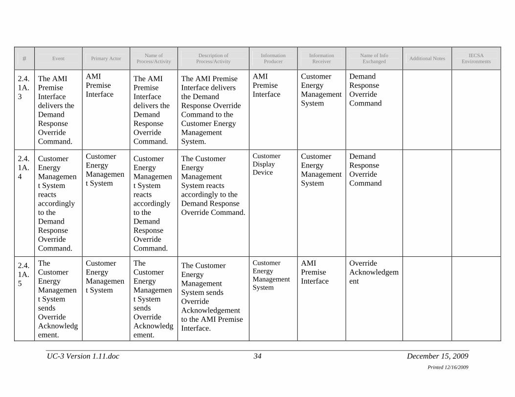
2.4.1A.3
The AMI Premise Interface delivers the Demand Response Override Command.
AMI Premise Interface
The AMI Premise Interface delivers the Demand Response Override Command.
The AMI Premise Interface delivers the Demand Response Override Command to the Customer Energy Management System.
AMI Premise Interface
Customer Energy Management System
Demand Response Override Command
2.4.1A.4
Customer Energy Management System reacts accordingly to the Demand Response Override Command.
Customer Energy Management System
Customer Energy Management System reacts accordingly to the Demand Response Override Command.
The Customer Energy Management System reacts accordingly to the Demand Response Override Command.
Customer Display Device
Customer Energy Management System
Demand Response Override Command
2.4.1A.5
The Customer Energy Management System sends Override Acknowledgement.
Customer Energy Management System
The Customer Energy Management System sends Override Acknowledgement.
The Customer Energy Management System sends Override Acknowledgement to the AMI Premise Interface.
Customer Energy Management System
AMI Premise Interface
Override Acknowledgement
UC-3 Version 1.11.doc 34 December 15, 2009
Name of Description of Information Information Name of Info IECSA # Event Primary Actor Additional Notes
Printed 12/16/2009
Process/Activity Process/Activity Producer Receiver Exchanged Environments
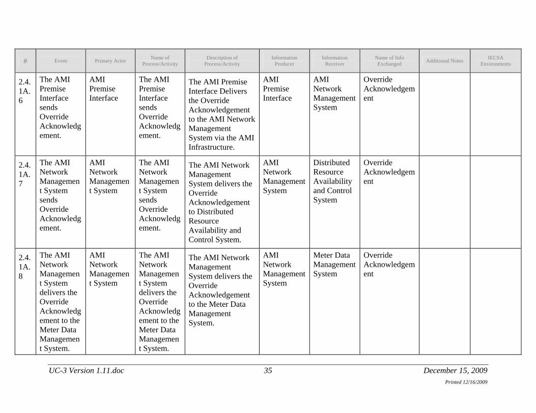
2.4.1A.6
The AMI Premise Interface sends Override Acknowledgement.
AMI Premise Interface
The AMI Premise Interface sends Override Acknowledgement.
The AMI Premise Interface Delivers the Override Acknowledgement to the AMI Network Management System via the AMI Infrastructure.
AMI Premise Interface
AMI Network Management System
Override Acknowledgement
2.4.1A.7
The AMI Network Management System sends Override Acknowledgement.
AMI Network Management System
The AMI Network Management System sends Override Acknowledgement.
The AMI Network Management System delivers the Override Acknowledgement to Distributed Resource Availability and Control System.
AMI Network Management System
Distributed Resource Availability and Control System
Override Acknowledgement
2.4.1A.8
The AMI Network Management System delivers the Override Acknowledgement to the Meter Data Management System.
AMI Network Management System
The AMI Network Management System delivers the Override Acknowledgement to the Meter Data Management System.
The AMI Network Management System delivers the Override Acknowledgement to the Meter Data Management System.
AMI Network Management System
Meter Data Management System
Override Acknowledgement
UC-3 Version 1.11.doc 35 December 15, 2009
Name of Description of Information Information Name of Info IECSA # Event Primary Actor Additional Notes
Printed 12/16/2009
Process/Activity Process/Activity Producer Receiver Exchanged Environments
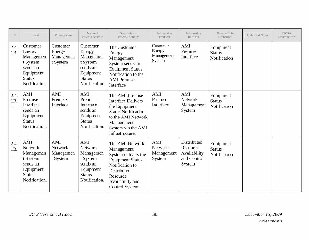
2.4.1B
Customer Energy Management System sends an Equipment Status Notification.
Customer Energy Management System
Customer Energy Management System sends an Equipment Status Notification.
The Customer Energy Management System sends an Equipment Status Notification to the AMI Premise Interface
Customer Energy Management System
AMI Premise Interface
Equipment Status Notification
2.4.1B.1
AMI Premise Interface sends an Equipment Status Notification.
AMI Premise Interface
AMI Premise Interface sends an Equipment Status Notification.
The AMI Premise Interface Delivers the Equipment Status Notification to the AMI Network Management System via the AMI Infrastructure.
AMI Premise Interface
AMI Network Management System
Equipment Status Notification
2.4.1B.1
AMI Network Management System sends an Equipment Status Notification.
AMI Network Management System
AMI Network Management System sends an Equipment Status Notification.
The AMI Network Management System delivers the Equipment Status Notification to Distributed Resource Availability and Control System.
AMI Network Management System
Distributed Resource Availability and Control System
Equipment Status Notification
UC-3 Version 1.11.doc 36 December 15, 2009

Name of Description of Information Information Name of Info IECSA # Event Primary Actor Additional Notes
Printed 12/16/2009
Process/Activity Process/Activity Producer Receiver Exchanged Environments
2.4.1B.2
AMI Network Management System delivers the Equipment Status Notification to the Meter Data Management System.
AMI Network Management System
AMI Network Management System delivers the Equipment Status Notification to the Meter Data Management System.
The AMI Network Management System delivers the Equipment Status Notification to the Meter Data Management System.
AMI Network Management System
Meter Data Management System
Equipment Status Notification
2.5 Distributed Resource Availability and Control System sends an AMI Net/Billing Meter Read Request to the AMI Network Management System.
Distributed Resource Availability and Control System
Distributed Resource Availability and Control System sends an AMI Net/Billing Meter Read Request to the AMI Network Management System..
Distributed Resource Availability and Control System sends an AMI Net/Billing Meter Read Request to the AMI Network Management System.
Distributed Resource Availability and Control System
AMI Network Management System
AMI Net/Billing Meter Read Request
UC-3 Version 1.11.doc 37 December 15, 2009
Name of Description of Information Information Name of Info IECSA # Event Primary Actor Additional Notes
Printed 12/16/2009
Process/Activity Process/Activity Producer Receiver Exchanged Environments
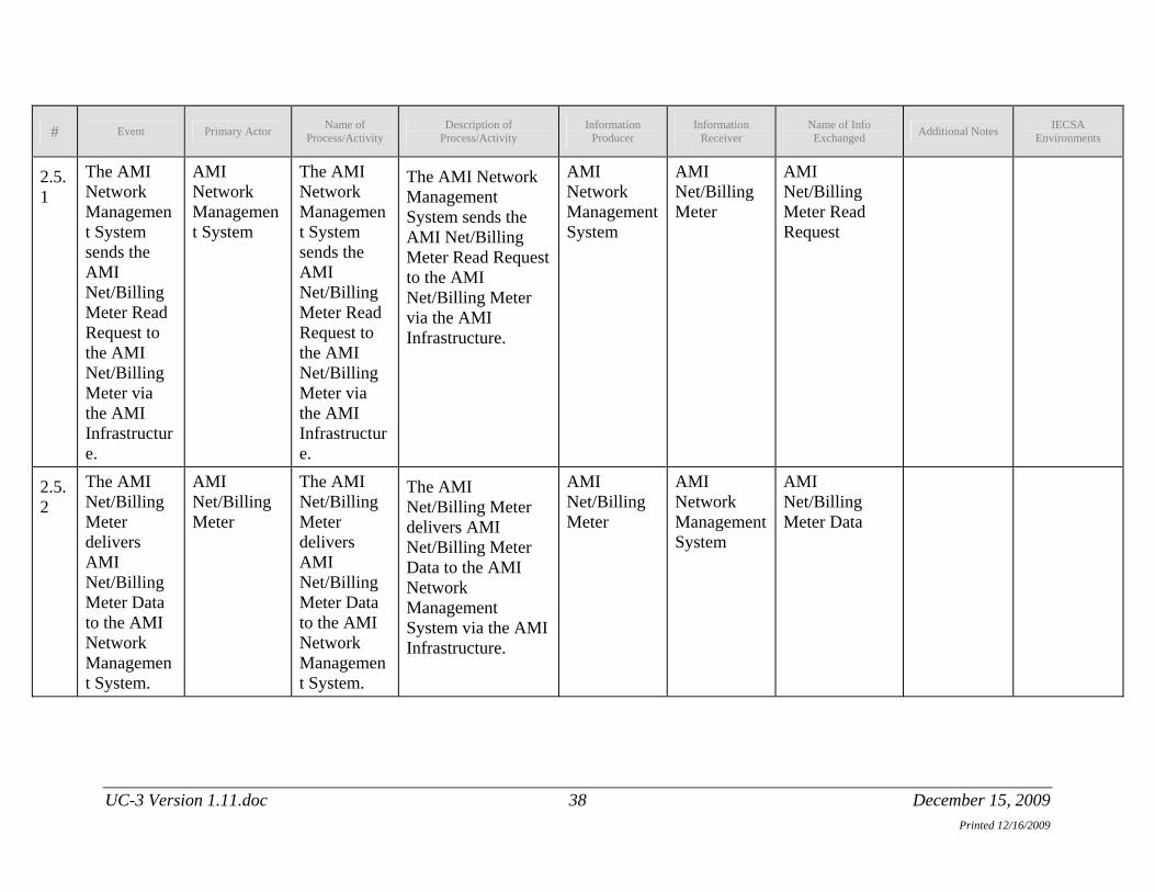
2.5.1
The AMI Network Management System sends the AMI Net/Billing Meter Read Request to the AMI Net/Billing Meter via the AMI Infrastructure.
AMI Network Management System
The AMI Network Management System sends the AMI Net/Billing Meter Read Request to the AMI Net/Billing Meter via the AMI Infrastructure.
The AMI Network Management System sends the AMI Net/Billing Meter Read Request to the AMI Net/Billing Meter via the AMI Infrastructure.
AMI Network Management System
AMI Net/Billing Meter
AMI Net/Billing Meter Read Request
2.5.2
The AMI Net/Billing Meter delivers AMI Net/Billing Meter Data to the AMI Network Management System.
AMI Net/Billing Meter
The AMI Net/Billing Meter delivers AMI Net/Billing Meter Data to the AMI Network Management System.
The AMI Net/Billing Meter delivers AMI Net/Billing Meter Data to the AMI Network Management System via the AMI Infrastructure.
AMI Net/Billing Meter
AMI Network Management System
AMI Net/Billing Meter Data
UC-3 Version 1.11.doc 38 December 15, 2009

Name of Description of Information Information Name of Info IECSA # Event Primary Actor Additional Notes
Printed 12/16/2009
Process/Activity Process/Activity Producer Receiver Exchanged Environments
2.5.3
The AMI Network Management System sends the AMI Net/Billing Meter Data to Distributed Resource Availability and Control System.
AMI Network Management System
The AMI Network Management System sends the AMI Net/Billing Meter Data to Distributed Resource Availability and Control System.
The AMI Network Management System sends the AMI Net/Billing Meter Data to Distributed Resource Availability and Control System.
AMI Network Management System
Distributed Resource Availability and Control System
AMI Net/Billing Meter Data
2.5.4
The AMI Network Management System delivers the AMI Net/Billing Meter Data to the Meter Data Management System.
AMI Network Management System
The AMI Network Management System delivers the AMI Net/Billing Meter Data to the Meter Data Management System.
The AMI Network Management System delivers the AMI Net/Billing Meter Data to the Meter Data Management System.
AMI Network Management System
Meter Data Management System
AMI Net/Billing Meter Data
UC-3 Version 1.11.doc 39 December 15, 2009

Name of Description of Information Information Name of Info IECSA # Event Primary Actor Additional Notes
Printed 12/16/2009
Process/Activity Process/Activity Producer Receiver Exchanged Environments
2.6 Meter Data Management System performs a calculation for the total load affected by the Demand Response Event.
Meter Data Management System
Meter Data Management System performs a calculation for the total load affected by the Demand Response Event.
Meter Data Management System performs a calculation and verification to calculate the total load affected by the Demand Response Event.
Meter Data Management System
Meter Data Management System
AMI Net/Billing Meter Data
2.6.1
Meter Data Management System delivers the total load affected by the Demand Response Event to the Wholesale Power Group.
Meter Data Management System
Meter Data Management System delivers the total load affected by the Demand Response Event to the Wholesale Power Group.
Meter Data Management System delivers the total load affected by the Demand Response Event to the Wholesale Power Group.
Meter Data Management System
Wholesale Power Group
Total Load Affected by the Demand Response Event
UC-3 Version 1.11.doc 40 December 15, 2009

Name of Description of Information Information Name of Info IECSA # Event Primary Actor Additional Notes
Printed 12/16/2009
Process/Activity Process/Activity Producer Receiver Exchanged Environments
2.6.2
Meter Data Management System delivers the total load affected by the Demand Response Event to the Distribution Management System.
Meter Data Management System
Meter Data Management System delivers the total load affected by the Demand Response Event to the Distribution Management System.
The Meter Data Management System delivers the total load affected by the Demand Response Event to the Distribution Management System.
Meter Data Management System
Distribution Management System
Total Load Affected by the Demand Response Event
2.6.3
Distribution Management System delivers the total load affected by the Demand Response Event to the Distribution Operations.
Distribution Management System
Distribution Management System delivers the total load affected by the Demand Response Event to the Distribution Operations.
The Distribution Management System displays the total load affected by the Demand Response Event to the Distribution Operations.
Distribution Management System
Distribution Operations
Total Load Affected by the Demand Response Event
2.2.3 Post-conditions and Significant Results Describe conditions that must exist at the conclusion of the Function. Identify significant items similar to that in the preconditions section.
Describe any significant results from the Function
UC-3 Version 1.11.doc 41 December 15, 2009
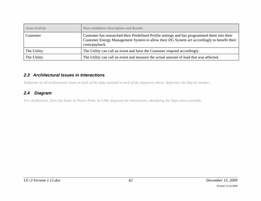
Actor/Activity Post-conditions Description and Results
Customer Customer has researched their Predefined Profile settings and has programmed them into their Customer Energy Management System to allow their DG System act accordingly to benefit their costs/payback.
The Utility The Utility can call an event and have the Customer respond accordingly. The Utility The Utility can call an event and measure the actual amount of load that was affected.
2.3 Architectural Issues in Interactions Elaborate on all architectural issues in each of the steps outlined in each of the sequences above. Reference the Step by number..
2.4 Diagram For clarification, draw (by hand, by Power Point, by UML diagram) the interactions, identifying the Steps where possible.
UC-3 Version 1.11.doc 42 December 15, 2009 Printed 12/16/2009
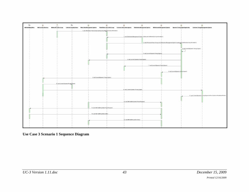
Use Case 3 Scenario 1 Sequence Diagram
UC-3 Version 1.11.doc 43 December 15, 2009 Printed 12/16/2009

3 Auxiliary Issues
3.1 References and contacts Documents and individuals or organizations used as background to the function described; other functions referenced by this function, or acting as “sub” functions; or other documentation that clarifies the requirements or activities described. All prior work (intellectual property of the company or individual) or proprietary (non-publicly available) work must be so noted.
FUTURE USE
ID Title or contact Reference or contact information
[1] ANSI C84.1-1995 Electrical Power Systems and Equipment – Voltage Ratings (60HZ)
ANSI A and ANSI B Voltage Requirements
[2]
3.2 Action Item List As the function is developed, identify issues that still need clarification, resolution, or other notice taken of them. This can act as an Action Item list.
FUTURE USE
ID Description Status
[1]
[2]
3.3 Revision History For reference and tracking purposes, indicate who worked on describing this function, and what aspect they undertook.
UC-3 Version 1.11.doc 44 December 15, 2009 Printed 12/16/2009

FUTURE USE
No Date Author Description
1.1 8-11-09 Brian D. Green Draft for Review
1.2 8-13-09 Brian D. Green Update Equipment Interfaces
1.3 9-21-09 Brian D. Green Change to new template
1.4 9-23-09 Brian D. Green Identify missing Information Objects, remove unnecessary steps and re-number.
1.6 9-28-09 Ronald J. Pasquarelli
Updates for import into IKB.
1.7 9-29-09 Ronald J. Pasquarelli
Remove old sequence diagrams
1.8 10-2-09 Ronald J. Pasquarelli
Cleanup- add actor the Utility, remove policy
1.9 10-06-09 Brian D. Green Cleanup – Actors
1.10 12-01-09 Brian D. Green Change actor name from Retail Rates and Tariffs Group to Price Origination Group
1.11 12-15-09 Brian D. Green Make the document generic and ready for posting on EPRI’s Smart Grid Use Case Repository.
3.4 Common Terms and Definitions As the function is developed, identify issues that still need clarification, resolution, or other notice taken of them. This can act as an Action Item list.
UC-3 Version 1.11.doc 45 December 15, 2009 Printed 12/16/2009

ID Term Definition
[1] Feeder Penetration PV penetration is the rated capacity (KW) of the aggregated generation, including the proposed Generating Facility compared to the annual peak load (KW) as most recently measured at the substation or calculated for that portion of a public utility’s electric system connected to a Customer bounded by automatic sectionalizing devices or the end of the distribution line. Units are % of peak on the feeder or portion of a public utility’s electric system In Manuel’s discussions with the state, “DG will be viewed by the rating of devices at point of common coupling.”
[2] Advanced Metering Infrastructure (AMI) “AMI” for the Utility for this project- refers to systems that measure, collect and analyze energy usage, and send information to the Customer through advanced electricity meters, via various communication media on request or on a pre-defined schedule. This infrastructure includes advanced electrical meters, communications, and meter (MDM) software. The communication between the end use energy consumer and the utility is two way communications. The AMI infrastructure and communications for the purposes of this project ends at the meter, which provides a Premise Interface to the Inverter or possibly the Home Area Network.
[3] AMI Premise Interface The Premise Interface is one of the communications radios “under glass” of the AMI Meter. (There are two radios built in to the AMI Meter. One is for the AMI System and is a longer range radio. The other is for the Premise Interface and it has a smaller range.) This interfaces to the Customer Inverter and the Home Area Network (if available).
UC-3 Version 1.11.doc 46 December 15, 2009 Printed 12/16/2009
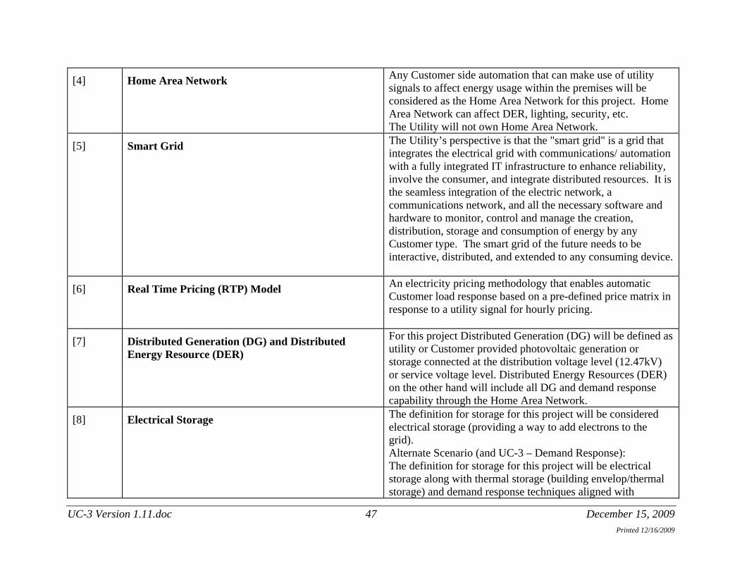
[4] Home Area Network Any Customer side automation that can make use of utility signals to affect energy usage within the premises will be considered as the Home Area Network for this project. Home Area Network can affect DER, lighting, security, etc. The Utility will not own Home Area Network.
[5] Smart Grid The Utility’s perspective is that the "smart grid" is a grid that integrates the electrical grid with communications/ automation with a fully integrated IT infrastructure to enhance reliability, involve the consumer, and integrate distributed resources. It is the seamless integration of the electric network, a communications network, and all the necessary software and hardware to monitor, control and manage the creation, distribution, storage and consumption of energy by any Customer type. The smart grid of the future needs to be interactive, distributed, and extended to any consuming device.
[6] Real Time Pricing (RTP) Model An electricity pricing methodology that enables automatic Customer load response based on a pre-defined price matrix in response to a utility signal for hourly pricing.
[7] Distributed Generation (DG) and Distributed Energy Resource (DER)
For this project Distributed Generation (DG) will be defined as utility or Customer provided photovoltaic generation or storage connected at the distribution voltage level (12.47kV) or service voltage level. Distributed Energy Resources (DER) on the other hand will include all DG and demand response capability through the Home Area Network.
[8] Electrical Storage The definition for storage for this project will be considered electrical storage (providing a way to add electrons to the grid). Alternate Scenario (and UC-3 – Demand Response): The definition for storage for this project will be electrical storage along with thermal storage (building envelop/thermal storage) and demand response techniques aligned with
UC-3 Version 1.11.doc 47 December 15, 2009 Printed 12/16/2009
commercial and residential cooling and refrigeration systems in addition to innovative approaches to demand response aligned with data center energy consumption.
UC-3 Version 1.11.doc 48 December 15, 2009 Printed 12/16/2009