1. Collision Theory 2. Factors affecting rate 3. Investigate how concentration affects rate.

1
Collision-aware Design of Rate Adaptation for
Multi-rate 802.11 WLANs
Jaehyuk Choi, Jongkeun Na, Yeon-sup Lim, Kihong Park, Member, IEEE,
and Chong-kwon Kim, Member, IEEE
Abstract
One of the key challenges in designing a rate adaptation scheme for IEEE 802.11 wireless LANs
(WLANs) is to differentiate bit errors from link-layer collisions. Many recent rate adaptation schemes
adopt the RTS/CTS mechanism to prevent collision losses from triggering unnecessary rate decrease.
However, the RTS/CTS handshake incurs significant overhead and is rarely activated in today’s infras-
tructure WLANs. In this paper we propose a new rate adaptation scheme that mitigates the collision
effect on the operation of rate adaptation. In contrast to previous approaches adopting fixed rate-
increasing and decreasing thresholds, our scheme varies threshold values based on the measured network
status. Using the “retry” information in 802.11 MAC headers as feedback, we enable the transmitter to
gauge current network state. The proposed rate adaptation scheme does not require additional probing
overhead incurred by RTS/CTS exchanges and can be easily deployed without changes in firmware. We
demonstrate the effectiveness of our solution by comparing with existing approaches through extensive
simulations.
Index Terms
Rate Adaptation, 802.11, Adaptive threshold
Manuscript received November 2, 2007; revised June 20, 2008. This work was supported in part by the Smart City Project
funded by the Seoul R&BD Program.
J. Choi, Y. Lim and C. Kim are with the Dept. of Computer Science and Engineering, Seoul National University, Seoul,
151-744 Korea, e-mail: {jhchoi, ylim, ckim}@popeye.snu.ac.kr.
J. Na is with the Dept. of Computer Sciences, University of Southern California, CA 90033, U.S.A, e-mail: [email protected].
K. Park is with the Dept. of Computer Sciences, Purdue University, IN 47907, U.S.A, e-mail: [email protected].
2
I. INTRODUCTION
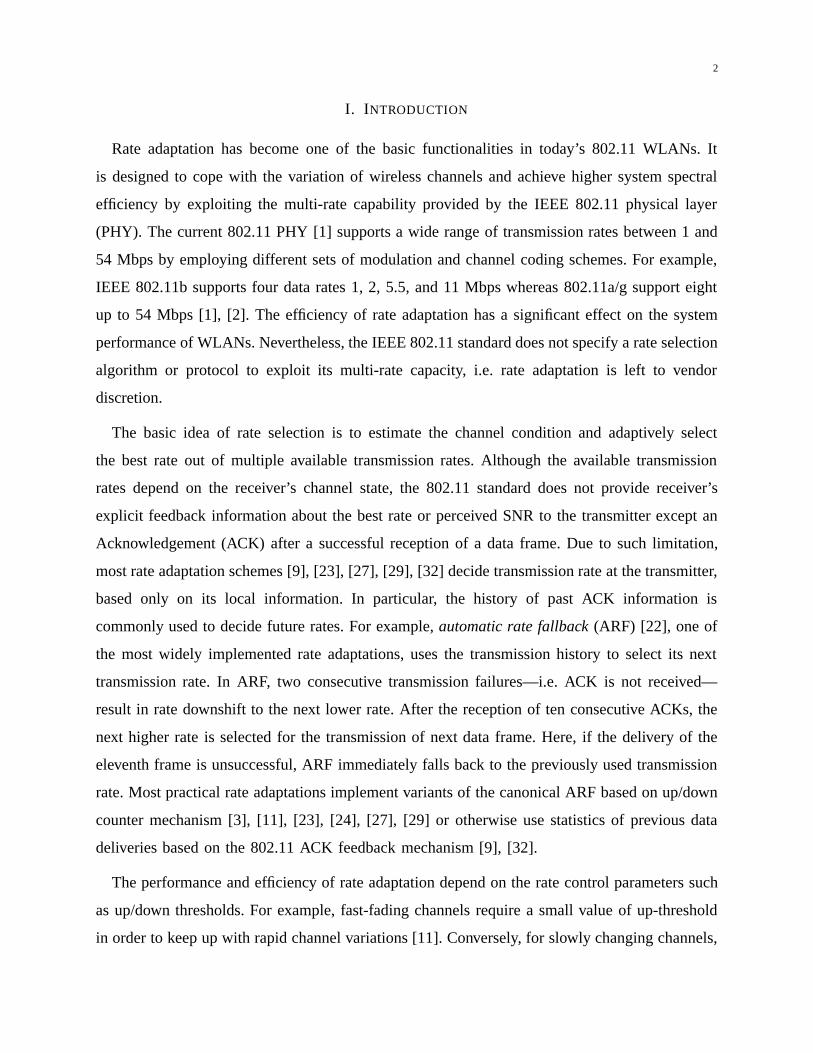
Rate adaptation has become one of the basic functionalities in today’s 802.11 WLANs. It
is designed to cope with the variation of wireless channels and achieve higher system spectral
efficiency by exploiting the multi-rate capability provided by the IEEE 802.11 physical layer
(PHY). The current 802.11 PHY [1] supports a wide range of transmission rates between 1 and
54 Mbps by employing different sets of modulation and channel coding schemes. For example,
IEEE 802.11b supports four data rates 1, 2, 5.5, and 11 Mbps whereas 802.11a/g support eight
up to 54 Mbps [1], [2]. The efficiency of rate adaptation has a significant effect on the system
performance of WLANs. Nevertheless, the IEEE 802.11 standard does not specify a rate selection
algorithm or protocol to exploit its multi-rate capacity, i.e. rate adaptation is left to vendor
discretion.
The basic idea of rate selection is to estimate the channel condition and adaptively select
the best rate out of multiple available transmission rates. Although the available transmission
rates depend on the receiver’s channel state, the 802.11 standard does not provide receiver’s
explicit feedback information about the best rate or perceived SNR to the transmitter except an
Acknowledgement (ACK) after a successful reception of a data frame. Due to such limitation,
most rate adaptation schemes [9], [23], [27], [29], [32] decide transmission rate at the transmitter,
based only on its local information. In particular, the history of past ACK information is
commonly used to decide future rates. For example, automatic rate fallback (ARF) [22], one of
the most widely implemented rate adaptations, uses the transmission history to select its next
transmission rate. In ARF, two consecutive transmission failures—i.e. ACK is not received—
result in rate downshift to the next lower rate. After the reception of ten consecutive ACKs, the
next higher rate is selected for the transmission of next data frame. Here, if the delivery of the
eleventh frame is unsuccessful, ARF immediately falls back to the previously used transmission
rate. Most practical rate adaptations implement variants of the canonical ARF based on up/down
counter mechanism [3], [11], [23], [24], [27], [29] or otherwise use statistics of previous data
deliveries based on the 802.11 ACK feedback mechanism [9], [32].
The performance and efficiency of rate adaptation depend on the rate control parameters such
as up/down thresholds. For example, fast-fading channels require a small value of up-threshold
in order to keep up with rapid channel variations [11]. Conversely, for slowly changing channels,

3
the use of a large value of up-threshold can prevent excessive rate-increasing attempts. Several
research efforts [11], [24], [29] have dealt with time-varying wireless channel characteristics
through adaptive up/down-thresholds.
Unfortunately, most rate adaptations only focus on the time-varying characteristics of wireless
channels and do not consider the impact of link-layer collisions. They assume that all transmission
failures—inferred from missing 802.11 ACKs—are due to channel errors even though absence
of an ACK is not always due to channel error, i.e., many transmission failures are due to link-
layer collisions in multi-user contention-based 802.11 networks. As a result, they respond to
frame collisions—which cannot be distinguished from channel errors based on missing 802.11
ACKs alone—resulting in unnecessary rate downshift (to be more robust to bit-errors) even
when channel condition is not bad. This can significantly decrease throughput when transmission
failures are caused by collisions [13], [15], [23].
To mitigate the collision effect, a number of recently proposed schemes [19], [23], [27], [32]
leverage the per-frame RTS option and selectively turn on RTS/CTS exchange. The feedback
information obtained from the RTS/CTS handshake can enable the transmitter to differentiate
collisions (i.e., indicated by a failure of RTS frame) from channel errors (i.e., indicated by a
unsuccessful data frame transmission following a successful RTS/CTS handshake). However,
RTS/CTS is rarely turned on in practical infrastructure IEEE 802.11 WLANs due to high
overhead. Per-frame selective RTS also remains a costly solution in lossy environments.
In this paper, we address the performance degradation problem of rate adaptation stemming
from detrimental rate-down shift operations wrongly triggered by link-layer collisions. Our main
objective is to find a solution that does not require additional probing overhead such as those
incurred by RTS/CTS exchanges. Our key idea is that dynamic adjustment of up/down-thresholds
can be useful not only to cope with channel dynamics [11], [29] but also to mitigate the impact of
collisions. As the number of contending stations increases, the number of collisions is also likely
to increase triggering unnecessary—in fact, detrimental—rate-downshifts. In such a situation, a
higher value of down-threshold can reduce undesired rate-downshifts. Similarly, a smaller value
of up-threshold can help recover from unintended rate-decreases induced by collisions.
Motivated by the above observation, we present a new approach that mitigates the collision

4
effect on the operation of rate adaptation in IEEE 802.11 WLANs by adaptively adjusting the
rate-increasing and decreasing parameters. Instead of distinguishing between channel errors and
collisions based on costly RTS/CTS mechanism, we use a link-layer congestion metric that infers
network congestion state gauged by local observations at the transmitter. We develop a novel
congestion sensing technique by exploiting the 802.11 standard’s retransmission mechanism, in
particular, the Retry field in 802.11 MAC header which indicate whether a data or management
frame is being transmitted for the first time or is a retransmission. Our key observation is that
the pattern of this Retry field can be used as channel feedback for inferring channel contention
information since it is influenced by collision events. The main advantage of this metric is that
it can be easily measured by monitoring the retransmission state of frames being transmitted
in a WLAN without extra overhead. The result is then used to control the operating thresholds
adaptively so as to mitigate the collision effect on rate adaptation. The simulation results show
that our new estimation scheme based on the link-layer retransmission information is efficient in
gauging the channel state, and the adaptively tuned thresholds are effective not only at offsetting
the collision effect but also improving the responsiveness to channel variation. Our solution
does not require additional probing overhead and can be practically deployed without changes
in firmware.
The remainder of the paper is organized as follows. In Section II, we formulate the problem
and introduce the framework of our approach. Section III analyzes the impact of rate-control
parameters on system performance. In Section IV, we study adaptive threshold tuning. In Sec-
tion V, we present a new link-layer sensing technique that exploits the 802.11’s retransmission
protocol and propose a run-time algorithm to adaptively control the operating thresholds. The
performance of our solution is evaluated via extensive simulation in Section VI. We conclude
with a discussion of related work.
II. PROBLEM FORMULATION
We consider a station adopting ARF in a multi-rate IEEE 802.11 WLAN. Let θu and θd denote
the up and down thresholds of ARF, respectively, where θu consecutive successes trigger a rate
upshift (more precisely, up-rate probing to the next higher rate [22] [13]) and θd consecutive
transmission failures result in a rate downshift to the next lower rate. The canonical ARF uses
5
fixed thresholds θu = 10 and θd = 2. Note that other variants of the canonical ARF may
use different values or variable thresholds [11] [29]. For example, AARF [24] uses a binary
exponential up-threshold θu while its down-threshold θd is fixed at 2. The thresholds used in
these schemes do not consider the collision effect.
Our objective is to mitigate the unintended rate shift stemming from collisions. Instead of
RTS/CTS, we aim to improve the operation of rate adaptation by adjusting its rate-control
thresholds based on estimation of link-layer conditions. The goal of our approach is to find
new thresholds (xu, xd) offsetting the collision effect experienced under original operation with
(θu, θd). (xu, xd) is determined by current link-layer condition (i.e., collision probability) and
the thresholds (θu, θd) of target rate adaptation schemes. Thus, we can state the problem as
xu = fu(θu, p) and xd = fd(θd, p) (1)
where p represents the current link-layer contention status, i.e., collision probability. Finding the
threshold tuning functions fu(·) and fd(·) is the key problem.
The first challenge in deriving fu(·) and fd(·) is the lack of a target reference point for
up/down-thresholds that indicates what rate adaptation behavior is optimal to mitigate the colli-
sion effect. This issue is addressed next.
III. PERFORMANCE OF ARF AND ITS IDEAL BEHAVIOR
In this section we study the impact of up/down thresholds on ARF performance and show
that dynamic adjustment of thresholds is an effective way to mitigate the collision effect. We
use the ARF analysis model proposed in [13] to understand the rate-shifting behavior of ARF.
We first review the ARF Markov chain model briefly.
A. Analytic Model of ARF
The analysis considers a station adopting ARF in a multi-rate IEEE 802.11 WLAN with L
data rates R1 < R2 < · · · < RL in units of Mbps, where the WLAN consists of N stations.
For example, in 802.11b L = 4 with rates 1, 2, 5.5, and 11 Mbps. For each rate Ri and
given a fixed frame size, the station is supposed to have a frame error rate (FER) ei obeying
e1 ≤ e2 ≤ · · · ≤ eL due to the increased robustness of 802.11 PHY modulation at lower data
6
rates. Following Bianchi [7], we introduce the independence assumption that in equilibrium a
frame transmission experiences collisions with constant and independent probability p. Thus
the conditional transmission failure probability of a frame transmitted at rate Ri is given by
pi = 1− (1− p)(1− ei). Note that even though the transmission failure probability pi consists
of p and ei, ARF can not recognize p and ei separately and it only behaves according to the
aggregated value of pi.
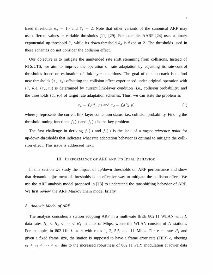
The key observation we can find in the ARF algorithm is that the transmission rate is always
switched to adjacent one, so that the rate adaptation procedure of ARF could be expressed via a
birth-death Markov chain as shown in Fig. 1, where the state i represents the transmission rate
Ri of the single target station. Note that each state in this chain is a macro-state which contains
micro-states representing the consecutive counters of ARF (the details are described in [13]).
1 2 i L
λ1
µ2
λ2
µ3 µi
λi λL-1
µL
λi-1
µi+1
Fig. 1. Birth-death Markov Chain for ARF (L PHY rates)
Let Πi denote the steady-state probability of the ARF chain that captures a station’s probability
of transmitting at data rate Ri. λi (i ∈ {1, 2, . . . , L − 1}) and µi (i ∈ {2, . . . , L}) denote the
state transition probabilities of increasing the current rate i to i + 1 and decreasing the current
rate i to i − 1, respectively. The equilibrium distribution of a L-state discrete-time birth-death
chain with birth probabilities λi and death probabilities µi is given by
Π1 =1
1 +∑L−1
j=1 (∏j
k=1λk
µk+1)
and Πi =λi−1
µi
Πi−1, (2)
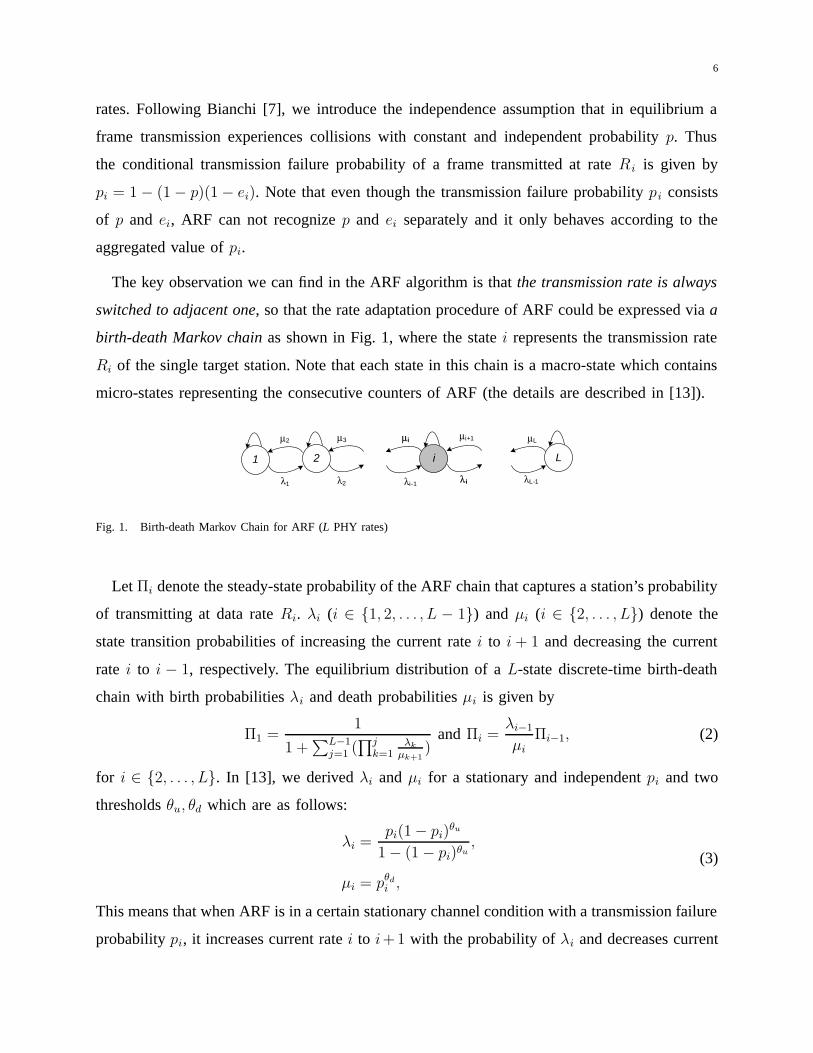
for i ∈ {2, . . . , L}. In [13], we derived λi and µi for a stationary and independent pi and two
thresholds θu, θd which are as follows:
λi =pi(1− pi)
θu
1− (1− pi)θu,
µi = pθdi ,
(3)
This means that when ARF is in a certain stationary channel condition with a transmission failure
probability pi, it increases current rate i to i+1 with the probability of λi and decreases current

7
rate i to i− 1 with the probability of µi. Eq. (3) also implies that the rate-shifting probabilities
can be controlled by adjusting thresholds θu and θd. It is of practical importance to understand
the behavior of ARF and improve its performance.
B. Impact of Thresholds on ARF Performance
Using the ARF analysis model, we now characterize the impact of both link-layer contention
and up/down thresholds on ARF performance. Fig. 2 shows ARF-DCF throughput in 802.11b
PHY environment for different combinations of the up/down thresholds as the number of contend-
ing station N is varied. We consider a stationary (i.e., no fading) channel state of SINR=9dB
at which BER11Mbps = 10-3, where we use empirical BER versus SNR curves provided by
Intersil [4]. All stations use equal up/down thresholds.
6
5
4
3
2
1
0 3 6 9 12 15 18 21 24
Thr
ough
put (
Mbp
s)
Number of Nodes
ARF (θu=2,θd=10) ARF (2, 5)ARF (2, 2)ARF (5, 2)
ARF (10, 2)
Fig. 2. ARF-DCF throughput for various θu and θd combinations at SINR=9dB (1000 bytes)
We observe that the performance of ARF is significantly influenced by both current link-layer
contention state and up/down-thresholds. When the number of stations N is small (N=1 or 2), the
default value θu=10 and θd=2 used in canonical-ARF achieves reasonable performance. However,
its performance drops precipitously as the number of contending station N increases. The steep
decline in throughput is caused by ARF’s inability to effectively differentiate channel noise from
collision. With θu = 2 and θd = 10, thanks to its large value of down-threshold, ARF avoids
the detrimental rate-down shift due to collisions and achieves high performance even at the high
contention region (i.e., large N). However, since the large threshold value is apt to slow down

8
responsiveness of rate selection, it can be harmful in fast-fading channel environments [11], [29].
The results imply that dynamic tuning of thresholds may be effective at mitigating the collision
effect but excessive tuning may hurt the ARF’s innate responsiveness to channel variation. Thus,
tuning should be done adaptively depending on network condition.
C. Ideal Behavior of ARF
As discussed in the previous section, it is well-known that when a WLAN has a number of
active stations, It is known that in a WLAN with moderate multiple access contention ARF may
lose its effectiveness due to the detrimental rate down-shift wrongly triggered by collisions [15].
To remedy this problem, ARF should not react to collisions but respond only to channel errors,
i.e., frame losses due to collisions should be filtered out from ARF’s failure counting.
Let us consider the ideal case where a station has perfect knowledge of the cause of transmis-
sion failures without additional probing overhead such as RTS/CTS exchange. Its rate adaptation
can perfectly prevent missteps due to collisions, and hence attain its maximum achievable
throughput. We refer to such ARF having perfect collision filtering ability as ideal ARF (or
Ideal Collision Filtering ARF). Even though ideal ARF is not realizable, we can analytically
characterize its behavior using our ARF Markov chain model.
Let Πopt
i (θu, θd) denote the probability of transmitting at rate Ri of ideal ARF with originally
configured up/down-thresholds θu and θd. As ideal ARF reacts only to channel errors, its response
probability to frame errors is not pi but (1−p)ei (= pi−p). Therefore, its transition probabilities
λopt
i , µopt
i at Ri are given by
λopt
i =(1− p)ei{1− (1− p)ei}θu
1− {1− (1− p)ei}θu,
µopt
i = {(1− p)ei}θd
(4)
which are obtained by substituting (pi − p) for pi into Eq. (3). Similarly, we can obtain the
probabilities Πopt
i (θu, θd) (i ∈ {1, . . . , L}) using Eq. (2). In Fig. 3, we compare the throughput
of ARF and ideal ARF for θu=10 and θd=2 as an example (same channel condition as Fig. 2).
Eqs. (4) characterize the optimal behavior of ARF that alleviates the collision effect. We use
λopt
i and µopt
i as the target reference value to control up/down-thresholds in our algorithm.

9
6
5
4
3
2
1
0 3 6 9 12 15 18 21 24
Thr
ough
put (
Mbp
s)Number of Nodes
SNR 9 dB - Ideal ARFSNR 9 dB - ARF
Fig. 3. Performance of ideal ARF (θu=10, θd=2) at SINR=9dB (1000 bytes)
IV. COLLISION-AWARE THRESHOLD TUNING
Our objective in this section is to find new collision-robust thresholds (xu, xd) in place of the
original thresholds (θu, θd) that offset the collision effect experienced when working with (θu,
θd).
A. Basic Idea
When ARF with thresholds (θu,θd) experiences stationary and independent transmission failure
probability pi (following [7]), its rate-shifting probabilities λi, µi are calculated as in Eq. (3)
while its ideal behavior follows λopt
i , µopt
i in Eqs. (4). The difference between these probabilities,
i.e., λopt
i − λi and µi − µopt
i , can be regarded as the impact of collision on ARF’s rate-shifting
where λopt
i − λi = 0 and µi − µopt
i = 0 if p = 0.
As shown in Eq. (3), the rate-shifting probabilities λi, µi of ARF can be controlled by adjusting
its thresholds. A change in λi, µi induces a change in λopt
i − λi and µi − µopt
i that quantify the
collision effect. Thus, we select the up-threshold and down-threshold that minimize λopt
i − λi
and µi − µopt
i as new up-threshold xu and down-threshold xd, respectively. To formulate our
approach, let us denote the rate-shifting probabilities λi and µi in Eq. (3) as λi(θu, pi) and
µi(θd, pi). Similarly, we represent the ideal rate-shifting probabilities λopt
i and µopt
i in Eq. (4)
as λopt
i (θu, p, ei) and µopt
i (θu, p, ei). The collision mitigating thresholds xu, xd are obtained by

10
solving
λi(xu, pi) = λopt
i (θu, p, ei),
µi(xd, pi) = µopt
i (θd, p, ei),(5)
which yield
xu =ln λi
λi+pi
ln(1− pi)=
ln(1− p)ei(1− (1− p)ei)
θu
pi + p(1− (1− p)ei)θu
ln(1− pi),
xd =ln µi
ln pi
= θdln (1− p)ei
ln pi
,
(6)
where pi = 1− (1− p)(1− ei).
If we know the collision probability p and the frame error probability ei, we can obtain the
link-layer adaptive thresholds xu, xd using Eq. (6). This requires that stations estimate ei for
each rate (i ∈ {1, 2, . . . , L− 1}) and p separately. In practice, it is difficult to predict the instant
channel error rate accurately without modification of the 802.11 standard. ARF neither estimates
nor uses the transmission failure rate pi, to say nothing of ei. In our approach, we also avoid
estimation of ei. Instead, our scheme makes use of link-layer measurement as follows: even
though stations in a 802.11 WLAN cannot differentiate collisions from channel errors given
transmission failures, they can estimate the link-layer status (i.e., the collision probability p or
the number of competing stations N) by using existing on-line measurement and estimation
algorithms [8], [21], [25], [30]. In the next section, we discuss an estimation method for the
collision probability p.
B. Adaptive Threshold Independent of Channel Condition
Let us express xu, xd in Eq. (6) as xu = f ′u(θu, p, ei), xd = f ′
d(θd, p, ei). To design an algorithm
that does not require channel information such as Eq. (1), we need to remove the input term
ei in f ′u(θu, p, ei) and f ′
d(θd, p, ei). For a given collision probability p, the adaptive thresholds
xu, xd have different values according to channel error ei. Fig. 4 plots the f ′u(θu, p, ei) function
for several values of collision probability p with respect to all ei (0 < ei ≤ 1), i.e., p < pi ≤ 1,
where the rate-increasing threshold θu is set to 10. From Fig. 4, we can see that the range of
f ′u(·) (i.e., xu) for various ei is not large except when ei is large (pi ≈ 1). A notable observation
is that the conservative nature of rate adaptations keeps the channel condition at the low noise

11
0
1
2
3
4
5
6
7
8
9
10
0 0.1 0.2 0.3 0.4 0.5 0.6 0.7 0.8 0.9 1
x uFrame failure probability (pi)
p=0.01p=0.1p=0.2p=0.3p=0.4p=0.5
Fig. 4. xu = f ′u(θu, pi) for arbitrary channel condition (p < pi ≤ 1) for θu = 10
regime (i.e., rate adaptations select a transmission rate at which the channel noise is low). We
can thus ignore the high noise region (large ei) in Fig. 4. Since the range of xu for the effective
range of ei becomes narrow, we use an integer closest to xu for p < pi � 1 as the final value
of f ′u(·). To simplify the algorithm and avoid excessive control, we use a conservative heuristic
that sets xu = max {fu(θu, p, ei)} for ei (0 < ei ≤ 1). For example, we have chosen xu = 4.7
for p = 0.3 in Fig. 4. Similarly, we set xd = min {fd(θd, p, ei)} for ei (0 < ei ≤ 1). Note that
the smaller value of xu and larger value of xd imply more aggressive control.
We obtain the control function in Eq. (1) for thresholds (θu, θd) as follows:
xu = fu(θu, p) = maxp<pi≤1
{ ln(pi − p)(1− (pi − p))θu
pi + p(1− (pi − p))θu
ln(1− pi)
},
xd = fd(θd, p) = minp<pi≤1
{θd · ln (pi − p)
ln pi
}.
(7)
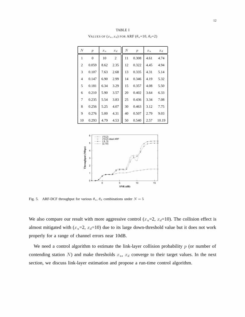
For example, we show the link-layer adaptive thresholds xu, xd for ARF (θu=10, θd=2) with
respect to the number of contending stations N and resultant collision probability p [7] in Table I.
Consider the case N = 5 whose collision probability is p = 0.181. For ARF working with default
thresholds θu=10 and θd=2, its adaptive thresholds are xu = fu(10, 5) = 6.34 and xd = fd(2,
5) = 3.29. Since thresholds should be integers, we round [xd] = 6, [xu] = 3. Fig. 5 compares
throughput (analytical result) under N = 5(p ≈ 0.18) for different combinations of up/down
thresholds over a wide range of channel conditions. Fig. 5 shows that for N = 5(p = 0.18),
our adaptive method (xu=6, xd=3) offsets the collision effect experienced under (θu=10, θd=2).
12
TABLE I
VALUES OF (xu, xd) FOR ARF (θu=10, θd=2)
N p xu xd
1 0 10 2
2 0.059 8.62 2.35
3 0.107 7.63 2.68
4 0.147 6.90 2.99
5 0.181 6.34 3.29
6 0.210 5.90 3.57
7 0.235 5.54 3.83
8 0.256 5.25 4.07
9 0.276 5.00 4.31
10 0.293 4.79 4.53
N p xu xd
11 0.308 4.61 4.74
12 0.322 4.45 4.94
13 0.335 4.31 5.14
14 0.346 4.19 5.32
15 0.357 4.08 5.50
20 0.402 3.64 6.33
25 0.436 3.34 7.08
30 0.463 3.12 7.75
40 0.507 2.79 9.03
50 0.540 2.57 10.19
6
5
4
3
2
1
0151050
Thr
ough
put (
Mbp
s)
SNR (dB)
(10,2) (10,2) ideal ARF( 6, 3) (2,10)
Fig. 5. ARF-DCF throughput for various θu, θd combinations under N = 5
We also compare our result with more aggressive control (xu=2, xd=10). The collision effect is
almost mitigated with (xu=2, xd=10) due to its large down-threshold value but it does not work
properly for a range of channel errors near 10dB.
We need a control algorithm to estimate the link-layer collision probability p (or number of
contending station N) and make thresholds xu, xd converge to their target values. In the next
section, we discuss link-layer estimation and propose a run-time control algorithm.

13
V. A NEW CONGESTION SENSING TECHNIQUE AND RUN-TIME ADAPTATION ALGORITHM
A. 802.11 Feedback for Inferring Network Status
In a WLAN, all contending stations experience a same collision probability while they have
different channel error probabilities. The collision probability p is a common shared variable of
all contending stations and can be measured by each individual station via monitoring the channel
state [8], [12], [14], [18], [21]. In particular, the number of idle slots between two consecutive
busy periods can be used to estimate the number of contending stations and collision probability.
We propose a new technique to estimate the number of active stations N (and collision
probability p) using the frequency of retransmitting frames in 802.11 WLANs. Fig. 6 shows the
FrameControl
Duration/ID
Address 1 Address 2 Address 3Sequence
ControlAddress 4
FrameBody
FCS
ProtocolVesion
Type SubtypeToDS
FromDS
MoreFrag
RetryPwrMgt
MoreData
WEP Order
Bits: 2 2 4 1 1 1 1 1 1 1 1
MAC Header
Octets: 2 2 6 6 6 62 40-2312
Fig. 6. General IEEE 802.11 MAC layer frame format
format of a general IEEE 802.11 MAC layer frame. The Retry field in the 802.11 MAC header
is a single bit and is used to indicate whether a data or management frame is being transmitted
for the first time or is a retransmission (0 or 1). The receiving MAC uses this indication to
aid in the process of eliminating duplicate frames. A key observation is that the retry field can
be used as channel feedback for inferring the channel condition because there is correlation
between collision probability and the pattern of retry values in arriving frames. As the channel
becomes more congested, the number of retransmissions is also likely to increase. When a station
detects frame transmission, it checks if the received frame is intended for itself by looking at
the receiver address field in MAC header. At this step, each station can inspect the value of
Retry field included in the MAC header. By exploiting the Retry field pattern, we can quantify
the degree of contention in the channel.

14
B. A Novel Congestion Sensing Technique
In order to model and analyze the pattern of Retry field, we reuse Bianchi’s Markov chain
model [7]. Fig. 7 shows a discrete-time Markov chain model that describes the backoff window
scheme of 802.11 DCF. Following [7], let b(t) and s(t) be the stochastic process representing
0, 1 0, 2 0, W0-2 0, W0-10, 0 . . .
. . . . . . . . . . . . . . . . . .p/W1
i-1, 0 . . .
i, 1 i, 2 i, Wi-2 i, Wi-1i, 0 . . .
p/Wi+1
. . .p/Wi
. . . . . . . . . . . . . . . . . .
m, 1 i, 2 i, Wm-2 i, Wm-1m, 0 . . .. . .p/Wm
1 1 11 1
1
1 1 1 1 1
1 1 1 1 1
. . .
p/Wm
. . .p/W0
(1-p)/W0
Successful TX with the Retry field set to 0
Successful TX with the Retry field set to 1 (Successful Retransmission)
(1-p)
(1-p)
(1-p)
(1-p)
Fig. 7. Markov Chain Model for the 802.11 DCF’s exponential backoff procedure proposed in [7]
the backoff window size for a given station and the stochastic process representing the backoff
stage (0, ..., m) of a station at time t, respectively, where m represents the maximum backoff
stage. The two-dimensional process {s(t), b(t)} is represented by state {s(t) = i, b(t) = k} at
time t. The stationary distribution of the chain is denoted by bi,k = limt→∞ P{s(t) = i, b(t) =
k} , i ∈ (0, m), k ∈ (0, Wi − 1), where Wi = 2iCWmin .
We describe the Retry field pattern using the Markov chain in Fig. 7. A transmission occurs
when the backoff time counter is equal to zero, hence a transition from states {i, 0} (i ∈ (0, m))
in the chain represents a frame transmission. The Retry field is set to 0 for the transmission from
the backoff stage 0, i.e., state {0, 0}, and set to 1 at other stages, i.e., states {k, 0}, k ∈ (1, m).

15
Upon successful reception of a frame, each station counts the frequencies of frames with the
retry field = 0 and 1. Let Cj (j = 0, 1) denote the numbers of frames whose Retry field is j.
We calculate the probability of successful transmissions at the first attempt as follows:
C0
C0 + C1=
(1− p)b0,0
(1− p)b0,0 + (1− p)∑m
k=1 bk,0. (8)
Using the relation bi,0 = pib0,0 [7], we obtain
C0
C0 + C1
=(1− p)b0,0
(1− p)∑m
k=0 bk,0
=1− p
1− pm(9)
which yields
pm + pm−1 + . . . + p− C1
C0= 0. (10)
With the measured value of C1/C0, we can calculate the collision probability p from Eq. (10). Ta-
ble II shows the relation between the number of contending stations N (and collision probability
p) and C1/C0 when the 802.11’s LongRetryLimit is 4 (i.e. m=4).
TABLE II
NUMBER OF CONTENDING STATIONS N , COLLISION PROBABILITY p AND CORRESPONDING C1/C0 (RETRYLIMIT = 4)
N p C1/C0
1 0.000 0.000
2 0.059 0.062
3 0.107 0.120
4 0.147 0.173
5 0.181 0.221
6 0.210 0.265
7 0.235 0.306
8 0.256 0.343
9 0.276 0.378
10 0.293 0.411
N p C1/C0
11 0.308 0.441
12 0.322 0.470
13 0.335 0.497
14 0.346 0.522
15 0.357 0.547
20 0.402 0.654
25 0.436 0.745
30 0.463 0.824
40 0.507 0.960
50 0.540 1.075
Note that retransmissions are induced not only by collisions but also channel errors. Therefore,
we have to consider the impact of channel errors. We first verify that C1/C0 is a reliable reference
even in the presence of channel errors.
16
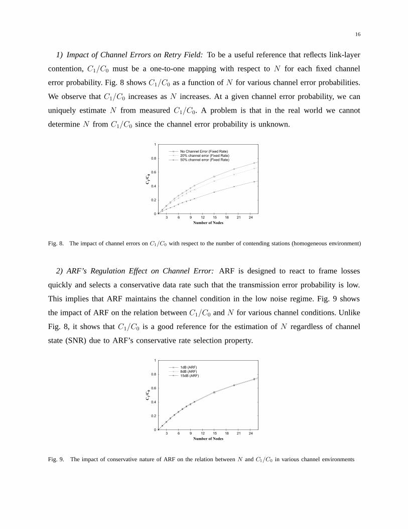
1) Impact of Channel Errors on Retry Field: To be a useful reference that reflects link-layer
contention, C1/C0 must be a one-to-one mapping with respect to N for each fixed channel
error probability. Fig. 8 shows C1/C0 as a function of N for various channel error probabilities.
We observe that C1/C0 increases as N increases. At a given channel error probability, we can
uniquely estimate N from measured C1/C0. A problem is that in the real world we cannot
determine N from C1/C0 since the channel error probability is unknown.
0
0.2
0.4
0.6
0.8
1
3 6 9 12 15 18 21 24
C1/
C0
Number of Nodes
No Channel Error (Fixed Rate) 20% channel error (Fixed Rate)50% channel error (Fixed Rate)
Fig. 8. The impact of channel errors on C1/C0 with respect to the number of contending stations (homogeneous environment)
2) ARF’s Regulation Effect on Channel Error: ARF is designed to react to frame losses
quickly and selects a conservative data rate such that the transmission error probability is low.
This implies that ARF maintains the channel condition in the low noise regime. Fig. 9 shows
the impact of ARF on the relation between C1/C0 and N for various channel conditions. Unlike
Fig. 8, it shows that C1/C0 is a good reference for the estimation of N regardless of channel
state (SNR) due to ARF’s conservative rate selection property.
0
0.2
0.4
0.6
0.8
1
3 6 9 12 15 18 21 24
C1/
C0
Number of Nodes
1dB (ARF) 8dB (ARF)15dB (ARF)
Fig. 9. The impact of conservative nature of ARF on the relation between N and C1/C0 in various channel environments

17
TABLE III
THRESHOLD TABLE FOR E[C1/C0] (θu=10, θd=2) : xu = fu(10, E[C1/C0]), xd = fd(2, E[C1/C0]), M = 5
E[C1/C0] (p) xu
−0.02 (<0.02) 10
0.02−0.06 (0.02−0.06) 9
0.06−0.12 (0.06−0.11) 8
0.12−0.20 (0.11−0.17) 7
0.20−0.31 (0.17−0.24) 6
0.31−0.47 (0.24−0.32) 5
0.47−0.70 (0.32−0.42) 4
0.70−1.11 (0.42−0.55) 3
1.11−2.11 (0.55−0.76) 2
2.11− (>0.76) 1
E[nIdle] (p) xd
−0.09 (<0.08) 2
0.09−0.25 (0.08−0.20) 3
0.25−0.41 (0.20−0.29) 4
0.41−0.55 (0.29−0.36) 5
0.55−0.68 (0.36−0.41) 6
0.68−0.78 (0.41−0.45) 7
0.78−0.91 (0.45−0.49) 8
0.91−1.00 (0.49−0.52) 9
1.00−1.11 (0.52−0.55) 10
1.11− (>0.55) 11
C. Control Algorithm
To provide run-time adaptive estimation reflecting the network dynamics, the estimation is
performed using a moving average as follows:
E[C1/C0]i ← (1− α) ·E[C1/C0]i−1 + α · (C1/C0)i. (11)
To reduce overhead, we do not calculate the collision probability p or number of contending
station N directly from the estimated C1/C0. Instead we prepare offline the threshold tuning
tables indexed by θu (and θd) and E[C1/C0], i.e., fu(θu, E[C1/C0]), fd(θd, E[C1/C0]). Thus,
we can obtain adaptive thresholds xunewand xdnew
by simple run-time table lookup indexed
by E[C1/C0]. For example, Table III is established for the initial thresholds (xu=10, xd=2). If
measured E[C1/C0] is 0.3, we select thresholds xunew= 6 and xdnew
= 4 as new operating
thresholds.
The currently used thresholds xu and xd are also updated using a moving average as follows:
xu ← (1− β) · xu + β · xunew,
xd ← (1− β) · xd + β · xdnew.
(12)

18
VI. PERFORMANCE EVALUATION
A. Simulation Setup
In this section, we evaluate the performance of the proposed scheme via ns-2 simulations [6].
We implemented our scheme in ns-2 v2.31. For comparison, we also implemented ARF [22]
and CARA [23]. All simulations are performed in an infrastructure WLAN with one AP and
multiple stations. We simulate the IEEE 802.11b PHY. Offered traffic is constant bit rate (CBR)
UDP traffic, and simulations are performed under saturated conditions. The moving average
coefficients in Eqs. (11), (12) are set to α=0.1 and β=0.5.
B. Accuracy of Link-layer Sensing Technique
0
0.2
0.4
0.6
0.8
1
5 10 15 20 25
C1/
C0
Number of Nodes
AnalysisSimulation
Fig. 10. C1/C0 as a function of N : Analysis vs. Simulation
The predictive accuracy of the proposed link-layer sensing technique is essential to our
threshold tuning. Thus, we first evaluate its accuracy by comparing the analytical results with
ns-2 simulations. Fig. 10 compares the values of C1/C0 obtained by analysis with simulation
for 802.11b as the number of contending stations N is varied. From Fig. 10, we observe a close
match between analysis and simulation results, which indicates that the link-layer condition (i.e.,
collision probability) is accurately estimated by our sensing technique.
C. Stationary Channel Condition
We now evaluate the impact of adaptive threshold tuning on throughput performance. We first
consider the scenario where the channel is stationary. We compare the following schemes: (1)

19
0
1
2
3
4
5
6
5 10 15 20 25
Thro
ughp
ut (M
bps)
Number of Nodes
ARFARF with RTS/CTSCARAAdaptive Thresholds
(a) 1000 bytes, SINR = 15dB
0
1
2
3
4
5
6
5 10 15 20 25
Thro
ughp
ut (M
bps)
Number of Nodes
ARFARF with RTS/CTSCARAAdaptive Thresholds
(b) 1000 bytes, SINR = 10dB
0
1
2
3
4
5 10 15 20 25
Thro
ughp
ut (M
bps)
Number of Nodes
ARFARF with RTS/CTSCARAAdaptive Thresholds
(c) 250 bytes, SINR = 15dB
0
1
2
3
4
5 10 15 20 25
Thro
ughp
ut (M
bps)
Number of Nodes
ARFARF with RTS/CTSCARAAdaptive Thresholds
(d) 250 bytes, SINR = 10dB
Fig. 11. Throughput comparison of our proposal (Adaptive Thresholds) against ARF, ARF with RTS/CTS, and CARA in
stationary channel condition at which (a) SINR=15dB, 1000 bytes (b) SINR=10dB, 1000 bytes (c) SINR=15dB, 250 bytes (d)
SINR=10dB, 250 bytes
ARF, (2) ARF using the RTS/CTS exchange (referred as to ARF+RTS), (3) CARA and (4) our
proposed link-layer adaptive scheme. The test schemes are compared with each other in terms
of aggregate system throughput (in Mbps). As indicated in Section V, we set the consecutive
success threshold (θu) to 10 and the consecutive failure threshold (θd) to 2 for ARF and CARA.
We use empirical BER (Bit Error Rate) vs. SNR (Signal-to-Noise Ratio) curves [4] to set the
FER (Frame Error Rate). The RTS/CTS frames are always transmitted at the lowest rate of 1
Mbps. We conduct the simulations under various channel states and different data frame sizes.
Fig. 11 presents the throughput performance of ARF, ARF+RTS, CARA, and our scheme
as the number of stations is increased from 1 to 25. The throughput of ARF suffers as the
number of stations increases. We observe that the cause of significant performance degradation
20
(a bell shaped throughput curve) of ARF is that ARF cannot differentiate collisions from channel
errors [15]. On the other hand, even as multiple access contention increases from 1 to 25, the
throughput of ARF+RTS remains flat, which implies that ARF+RTS filters out collisions from
channel errors using RTS/CTS exchanges. The results also show that our proposed adaptive
threshold scheme prevents performance degradation in the high contention regime (i.e., large
N). Moreover, the performance of our scheme is superior over a wide range of N . This is
because our scheme mitigates the collision effect without the use of RTS/CTS handshake thus
avoiding its overhead.
The overhead advantage of our method is expected to be more pronounced when considering
the distribution of Internet packet size. According to a report from Cooperative Association for
Internet Data Analysis (CAIDA) [26], actual Internet traffic has a peak at small size packets
under 100 bytes and another peak at 1500 bytes corresponding to TCP’s maximum transfer unit
(MTU). The cost of RTS/CTS overhead amplifies for small packets. We show the performance
for small packets (250 bytes payload) in Figs. 11(c) and (d).
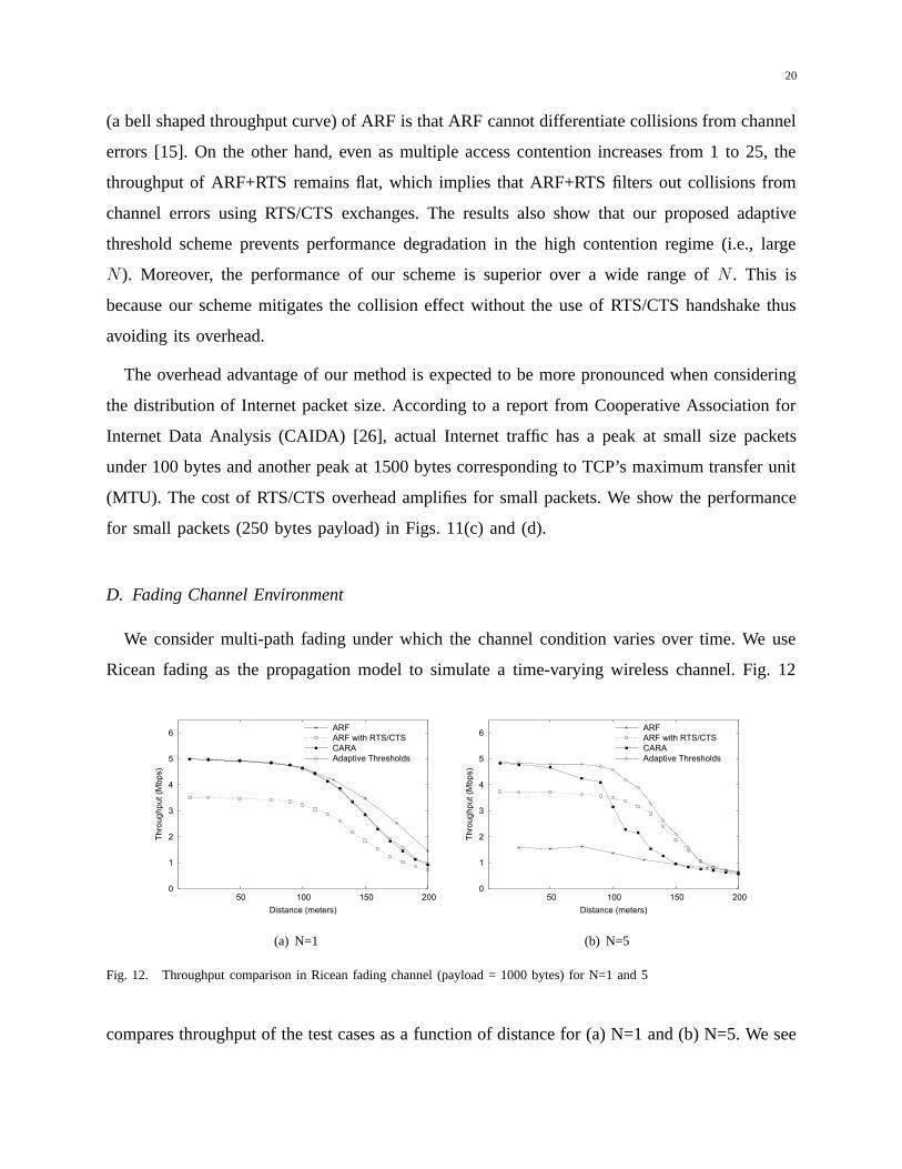
D. Fading Channel Environment
We consider multi-path fading under which the channel condition varies over time. We use
Ricean fading as the propagation model to simulate a time-varying wireless channel. Fig. 12
0
1
2
3
4
5
6
50 100 150 200
Thro
ughp
ut (M
bps)
Distance (meters)
ARFARF with RTS/CTSCARAAdaptive Thresholds
(a) N=1
0
1
2
3
4
5
6
50 100 150 200
Thro
ughp
ut (M
bps)
Distance (meters)
ARFARF with RTS/CTSCARAAdaptive Thresholds
(b) N=5
Fig. 12. Throughput comparison in Ricean fading channel (payload = 1000 bytes) for N=1 and 5
compares throughput of the test cases as a function of distance for (a) N=1 and (b) N=5. We see
21
that when the number of stations is one (Fig. 12(a)), the performance of ARF and our scheme
is almost the same since our method uses identical thresholds to ARF (there is no contention
in this case). CARA’s performance is slightly less than ours due to the overhead of selective
RTS/CTS exchanges. The ARF+RTS scheme performs worst due to the overhead of RTS/CTS
exchanges before every data transmission attempt. For the case of N = 5 (Fig. 12(b)), we see
that the performance of ARF significantly decreases due to its missteps at higher contention
levels. The result shows that our scheme significantly improves the performance of ARF and
performs best in the benchmark suite. The improvement is achieved thanks to the small value of
up-threshold xu which enables our scheme to react to time-varying channel quickly. This result
implies that the adaptive adjustment of the thresholds helps not only mitigate the collision effect
but also improve responsiveness to the channel variation.
VII. RELATED WORK
In recent years, rate adaptation has been an active research topic, and a number of algo-
rithms [11], [20], [23], [24], [27], [29], [31], [32] have been proposed. Rate adaptation is left
to vendors (i.e., is not specified in the IEEE 802.11 standard), yet its design plays a critical
role in determining overall system performance [13], [15]. ARF [22] is the most popular rate
adaptation, which has been extended in two directions; first, to improve its reactivity to time-
varying channels [11], [24], [28], [29], and second, to deal with ARF’s noise vs. collision
differentiation problem [19], [23], [27]. An overview of existing methods can be found in [27]
and [16]. To deal with the fast-fading and slow-fading wireless channels, the authors of [11]
enhanced ARF to adaptively use a short probing interval and a long probing interval. In [29],
a novel fast-responsive link adaptation scheme has been proposed, which directs the transmitter
station’s rate-increase attempts in a controlled manner such that the responsiveness of the link
adaptation scheme can achieve minimum rate-increasing attempts. Kim et al. [23] proposed a
modified ARF, called Collision-Aware Rate Adaptation (CARA), leveraging the per-frame RTS
option. CARA exploits the fact that RTS frames are small and always encoded at the lowest rate.
A RTS frame transmission failure is likely the result of collision whereas data frame transmission
failures following a successful RTS/CTS handshake are likely due to channel error. CARA shows
improved system performance thanks to its collision-awareness capability. The schemes proposed

22
in [19], [32] use RTS/CTS mechanisms similar to CARA. Whereas most works in ARF have
focused on improving performance through enhanced algorithms and protocol mechanisms, our
previous work [13] focused on improving understanding of ARF’s dynamics.
VIII. CONCLUSION
In this paper, we have proposed a new approach that mitigates the collision effect on the
operation of rate adaptation in IEEE 802.11 WLANs by adaptively adjusting the rate-increasing
and decreasing parameters. Unlike previous approaches based on explicit distinction between
channel errors and collisions using costly RTS/CTS, we utilize link-layer feedback at the trans-
mitter. We have developed a new link-layer sensing technique enabling the transmitter to acquire
the current contention status. We have proposed a run-time algorithm to adaptively control the
operating thresholds by simple run-time table lookup that captures the current network status
obtained by our sensing technique. Through ns-2 simulations, we have demonstrated that the
proposed solution effectively offsets the collision effect, yielding significant performance gains
compared to using fixed thresholds. The simulation results have also shown that our solution
improves responsiveness to channel variation. While we demonstrate our solution in the context
of ARF, the approach may be applicable to other sender-based schemes.
REFERENCES
[1] IEEE, Part 11: Wireless LAN Medium Access Control (MAC) and Physical Layer (PHY) Specifications. IEEE Std 802.11-
1999, 1999.
[2] IEEE 802.11g, Part 11: Wireless LAN Medium Access Control (MAC) and Physical Layer (PHY) Specifications: Further
Higher Data Rate Extension in the 2.4 GHz Band, Supplement to IEEE 802.11 Standard, 2003.
[3] http://www.enterasys.com/, online link.
[4] Intersil, “HFA3861B; Direct Sequence Spread Spectrum Baseband Processor,” 2000.
[5] Multiband Atheros Driver For WIFI. http://madwifi.org/
[6] “The Network Simulator. ns-2,” http://www.isi.edu/nsnam/ns/, online link.
[7] G. Bianchi, “Performance Analysis of the IEEE 802.11 Distributed Coordinated Function,” IEEE J. Selected Areas in
Commun., vol. 18, no. 3, pp. 535-547, 2000.
[8] G. Bianchi and I. Tinnirello, “Kalman filter Estimation of the Number of Competing Termincals in an IEEE 802.11 Network,”
in Proc IEEE INFOCOM’2003, vol.2, pp. 844-852, 2003.
[9] J. Bicket. “Bit-rate selection in wireless networks,” Master’s thesis, Massachusetts Institute of Technology, 2005.
[10] P. Chatzimisios, A. C. Boucouvalas, and V. Vitsas, “Performance Analysis of IEEE 802.11 DCF in Presence of Transmission
Errors,” in Proc. IEEE ICC’2004, pp. 3854-3858, 2002.

23
[11] P. Chevillat, J. Jelitto, A. Barreto, and H. Truong, “A Dynamic Link Adaptation Algorithm for IEEE 802.11a Wireless
LANs,” in Proc. IEEE ICC03, pp. 1141-1145, 2003.
[12] J. Choi, J. Na, K. Park, and C. Kim, “Adaptive Optimization of Rate Adaptation Algorithms in Multi-rate WLANs,” in
Appear. IEEE ICNP’07, 2007.
[13] J. Choi, K. Park, and C. Kim, “Cross-Layer Analysis of Rate Adaptation, DCF and TCP in Multi-Rate WLANs,” in Appear.
IEEE INFOCOM’07, 2007.
[14] J. Choi, J. Yoo, and C. Kim, “EBA: an enhancement of the IEEE 802.11 DCF via distributed reservation ,” IEEE Trans.
on Mobile Computing, vol.4, no. 4 , pp. 378-390, 2006.
[15] S. Choi, K. Park, and C. Kim, “On the Performance Characteristics of WLANs: Revisited,” in Proc. ACM SIGMETRICS’05,
pp. 97-108, 2005.
[16] I. Hatatcherev, K. Langendoen, R. Lagendijk, H. Sips, “Hybrid rate control for IEEE 802.11,” in Proc. ACM MobiWac’04,
pp. 10-18, 2004.
[17] M. Heusse, F. Rousseu, G. Berger-Sabbatel, and A. Duda, “Performance Anomaly of 802.11b,” in Proc. IEEE INFO-
COM’03, pp. 836-843, 2003.
[18] M. Heusse, F. Rousseu, R. Guilier, and A. Duda, “Idle Sense: An Optimal access Method for high throughput and Fairness
in Rate diverse wireless LANs,” in Proc. ACM SIGCOMM’05, pp. 121-132, 2005.
[19] C. Hoffmann, M. Manshaei, T. Turletti, “CLARA: closed-loop adaptive rate allocation for IEEE 802.11 wireless LANs,”
in Proc. IEEE WIRELESSCOM’05, pp. 668-673, 2005.
[20] G. Holland, N. Vaiday and P. Bahl, “A Rate-Adaptive MAC Protocol for Multi-Hop wireless Networks,” in Proc. ACM
MobiCom ’01, Jul. 2001.
[21] C. Hun, and J. C. Hou, “A Novel Approach to Contention Control in IEEE 802.11e-Operated WLANs,” to Appear. IEEE
INFOCOM’07, 2007.
[22] A. Kamerman and L. Monteban, “WaveLAN 2: A High-performance Wireless LAN for the Unlicensed Band,” Bell Labs
Tech. Journal, vol.2, no. 3 , pp. 118-133, 1997.
[23] J. Kim, S. Kim, S. Choi, and D. Qiao,“CARA: Collision-Aware Rate Adaptation for IEEE 802.11 WLANs,”inProc. IEEE
INFOCOM’06, pp. 1-11, 2006.
[24] M. Lacage, M. H. Manshaei, T. Turletti, “IEEE 802.11 rate adaptation: a practical approach,” in Proc. ACM MSWiM’04,
pp. 126-134, 2004.
[25] H. Ma, X. Li, H. Li, P. Zhang, S. Luo, and C. Yuan, “Dynamic Optimization of IEEE 802.11 CSMA/CA Based on the
Number of Competing stations,” in Proc IEEE ICC’2004, pp. 191-195, 2004.
[26] S. McCreary, and K. Claffy, “Trends in wide are IP traffic patterns: A view from Ames Internet Exchange,” ITC Specialist
Seminar, 2000
[27] Q. Pang, Leung, V. Liew, S. Liew, “A rate adaptation algorithm for IEEE 802.11 WLANs based on MAC-layer loss
differentiation,” in Proc. IEEE Broadband Networks’05, pp. 709-717, 2005.
[28] J.P. Pavon, S. Choi, “Link adaptation strategy for IEEE 802.11 WLAN via received signal strength measurement,” in IEEE
ICC 2003, pp.1108- 1113, 2003.
[29] D. Qiao and S. Choi, “Fast-Responsive Link Adaptation for IEEE 802.11 WLANs,” in Proc. IEEE ICC’05, pp. 3583-3588,
2005.
[30] D. Qiao and K. Shin, “Achieving efficient channel utilization and weighted fairness for data communications in IEEE
802.11 WLAN under the DCF,” in Proc. of International Workshop on Quality of Service, pp. 227-236, 2002.

24
[31] B. Sadeghi, V. Kanodia, A. Sabharwal and E. Knightly, “Opportunistic Media Access for Multirate Ad Hoc Networks,”
in in Proc. ACM MobiCom’02, pp. 24-35, 2002.
[32] H.Y. Wong, H. Yang, S. Lu, and V.Bharghavan, “Robust Rate Adaptation for 802.11 Wireless Networks,” in Proc. ACM
Mobicom’06, pp. 146-157, 2006
PLACE
PHOTO
HERE
Jaehyuk Choi received his BS degree in material science and engineering from Seoul National University
in 2003. He is currently a PhD degree candidate in the School of Computer Science and Engineering at
Seoul National University, Seoul, Korea. His current research interests are in the area of wireless/mobile
networks including wireless LAN, mesh networks, rate adaptation, data link layer protocols, and network
simulators. He received a Silver Award at the Samsung HumanTech Paper Contest in 2007.
PLACE
PHOTO
HERE
Jongkeun Na received the BS degree and the MS degree from Ajou University, Korea, both in computer
science and engineering, and the PhD degree in computer enigneering from Seoul National University,
Korea, in 1992, 1995, and 2007 respectively. He is doing a fellowship at University of Southern California,
California, USA. His current research interests are energy management, routing algorithms and protocols
in wireless sensor networks.
PLACE
PHOTO
HERE
Yeon-sup Lim received the BS degree in computer science and engineering from Seoul National Univer-
sity, Korea in 2007. He is currently pursuing the MS degree in the department of computer science and
engineering at Seoul National University, Korea. His current research interests include wireless networks
and mobile computing.

25
PLACE
PHOTO
HERE
Kihong Park is an Associate Professor in the Department of Computer Science at Purdue University. He
received a B.A. from Seoul National University and a Ph.D. in computer science from Boston University.
His research interests include QoS provisioning, traffic modeling, and network security. Dr. Park was
a Presidential University Fellow at Boston University, a recipient of the NSF CAREER Award, and a
Fellow-at-Large of the Santa Fe Institute.
PLACE
PHOTO
HERE
Chong-kwon Kim received the B.S. degree in industrial engineering from Seoul National University, the
M.S. degree in operations research from Georgia Institute of Technology, and the Ph.D. degree in Computer
Science from University of Illinois at Urbana-Champaign in 1981, 1982, and 1987, respectively. In 1987,
he joined Bellcore as a Member of Technical Staff and worked on Broadband ISDN and ATM. Since
1991, he has been with Seoul National University as a Professor in the School of Computer Science and
Engineering. His research interests include wireless and mobile networking, high speed network control,
distributed processing, and performance evaluation.