1 Classes #9 & #10 Civil Engineering Materials – CIVE 2110 Buckling Fall 2010 Dr. Gupta Dr....
21
1 Classes #9 & #10 Classes #9 & #10 Civil Engineering Materials – Civil Engineering Materials – CIVE 2110 CIVE 2110 Buckling Buckling Fall 2010 Fall 2010 Dr. Gupta Dr. Gupta Dr. Pickett Dr. Pickett
-
Upload
claribel-thornton -
Category
Documents
-
view
221 -
download
0
Transcript of 1 Classes #9 & #10 Civil Engineering Materials – CIVE 2110 Buckling Fall 2010 Dr. Gupta Dr....

11
Classes #9 & #10 Classes #9 & #10 Civil Engineering Materials – CIVE 2110Civil Engineering Materials – CIVE 2110
BucklingBuckling
Fall 2010Fall 2010
Dr. GuptaDr. Gupta
Dr. PickettDr. Pickett
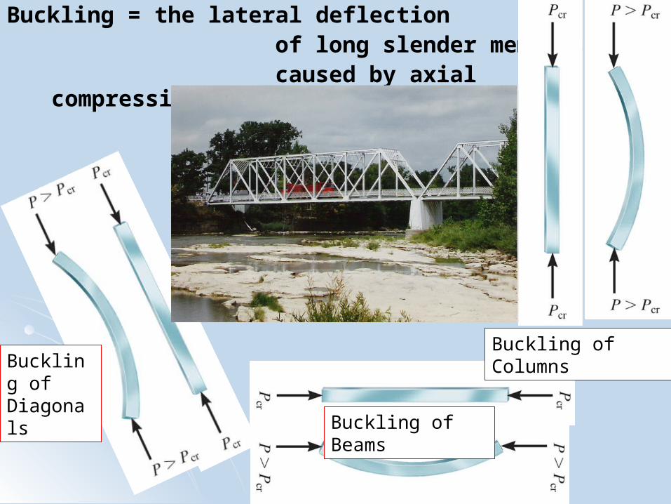
Buckling = the lateral deflection of long slender members caused by axial compressive forces
Buckling of ColumnsBuckling of Diagonals
Buckling of Beams

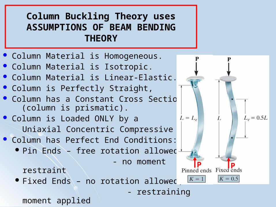
Column Buckling Theory uses ASSUMPTIONS OF BEAM BENDING THEORY
Column Length is Much Larger Than Column Width or Depth.
so most of the deflection is caused by bending,
very little deflection is caused by shear Column Deflections are small. Column has a Plane of Symmetry. Resultant of All Loads acts
in the Plane of Symmetry. Column has a Linear
Stress-Strain Relationship. Ecompression = Etension
σyield compression = σyield tension
σBuckle < (σyield ≈ σProportional Limit ).
Y
Y
E
σBuckle
Column Buckling Theory usesASSUMPTIONS OF BEAM BENDING
THEORY
Column Material is Homogeneous. Column Material is Isotropic. Column Material is Linear-Elastic. Column is Perfectly Straight, Column has a Constant Cross Section
(column is prismatic). Column is Loaded ONLY by a Uniaxial Concentric Compressive Load. Column has Perfect End Conditions:
Pin Ends – free rotation allowed, - no moment restraint Fixed Ends – no rotation allowed, - restraining moment applied
d
P P

Column Buckling Theory
An IDEAL Column will NOT buckle. IDEAL Column will fail by:
Punch thru Denting σ > σyield compressive .
Fracture
In order for an IDEAL Column to buckle
a TRANSVERSE Load, F,
must be applied
in addition to the
Concentric Uniaxial Compressive Load.
The TRANSVERSE Load, F, applied to IDEAL Column
Represents Imperfections in REAL Column
Pcr = Critical Load
Pcr = smallest load at which
column may buckle
F
P=Pcr
P=Pcr
P=Pcr
P=Pcr

Column Buckling Theory
Buckling is a mode of failure
caused by Structural Instability
due to a Compressive Load
- at no cross section of the member
is it necessary for
σ > σyield .
Three states of Equilibrium are possible for an Ideal Column Stable Equilibrium Neutral equilibrium Unstable Equilibrium
d
P=Pcr
P=Pcr

Column Buckling Theory – Equilibrium States
Stable Equilibrium
P<Pcr P<Pcr P<Pcr
P<Pcr P<PcrP<Pcr P=Pcr P=Pcr P=Pcr
P=PcrP=PcrP=Pcr
Neutral Equilibrium Unstable Equilibrium
P>Pcr P>Pcr P>Pcr
P>PcrP>PcrP>Pcr
Δ=small
F
F
FF
P>Pcr
P>Pcr
Δ=growsF F

Column Buckling Theory – Equilibrium States
Stable Equilibrium
P<Pcr P<Pcr P<Pcr
P<Pcr P<PcrP<Pcr P=Pcr P=Pcr P=Pcr
P=PcrP=PcrP=Pcr
Neutral Equilibrium Unstable Equilibrium
P>Pcr P>Pcr P>Pcr
P>PcrP>PcrP>Pcr
Δ=smallF
P>Pcr
P>Pcr
Δ=growsF
0Δ/L=
Pcr
P
0Δ/L=
Pcr
PIdeal Column
Real Column
Ideal Column
Real Column
0 Δ/L=
P Ideal Column
Real Column
Pcr
F

Deflection - BEAM BENDING THEORY
When a POSITVE moment is applied, (POSITIVE Bending)
TOP of beam is in COMPRESSION
BOTTOM of beam is in TENSION.
NEUTRAL SURFACE:
- plane on which
NO change
in LENGTH occurs.
Cross Sections
perpendicular to
Longitudinal axis
Rotate about the
NEUTRAL (Z) axis.
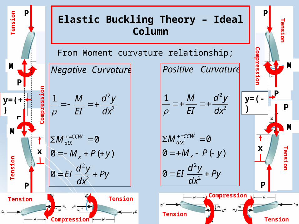
Elastic Buckling Theory – Ideal Column
From Moment curvature relationship;
Pydx
ydEI
yPM
M
dx
yd
EI
M
CurvatureNegative
x
CCWatX
2
2
2
2
0
)(0
0
1
P
Pydx
ydEI
yPM
M
dx
yd
EI
M
CurvaturePositive
x
CCWatX
2
2
2
2
0
)(0
0
1
P P
P
PP
PP
P
M
y=(+)
M
x
y=(-)
M
M
x
Tension Tension
Ten
sion
Tension
Ten
sion
Ten
sio
nT
ensi
on
Co
mp
ress
ion
Co
mp
ression
TensionCompression
Compression

Elastic Buckling Theory – Ideal Column
EI
PxBCos
EI
PxASiny
becomessolutiontheEI
PmThusEImP
mxBCosmxASinEImP
mxBCosmxASinPmxBCosmxASinEIm
Pydx
ydEIoSubstitue
mxBCosmmxASinmdx
yd
mxmBSinmxmACosdx
dy
mxBCosmxASinyAssume
Pydx
ydEICurvatureEitherFor
:
:0
)()(0
)()()()(0
0:int
)()(
)()(
)()(:
0:
2
2
2
2
2
222
2
2
2
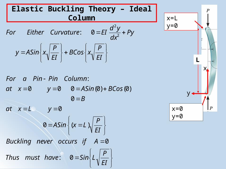
Elastic Buckling Theory – Ideal Column
EI
PLSinhavemustThus
AifoccursneverBuckling
EI
PLxASin
yLxat
B
BCosASinyxat
ColumnPinPinaFor
EI
PxBCos
EI
PxASiny
Pydx
ydEICurvatureEitherFor
0:
0
)(0
0
0
)0()0(000
:
0:2
2
x
y
L
x=0 y=0
x=L y=0

Elastic Buckling Theory – Ideal Column
2
2
2
22
1,
:
.,.........3,2,,0
0
0:
:
:
L
EIP
nwhenLoadLowestP
bucklemaycolumnwhichatLoadLowestPP
shapebuckledtheinL
EInPThus
wavesSinehalfofnumbernnEI
PL
atfunctionSinThe
EI
PLSinhavemust
ColumnPinPinaFor
EI
PxBCos
EI
PxASinyisequationBucklingThe
critical
cr
crcritical
x
y
L
x=0 y=0
x=L y=0

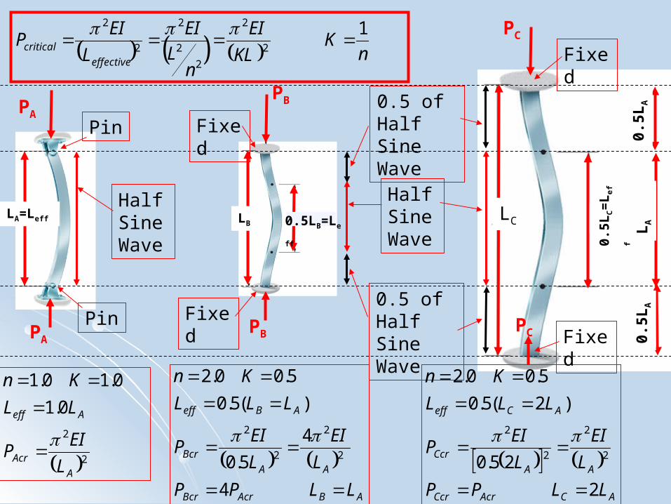
Elastic Buckling Theory – Ideal Column
factorlengtheffectiveK
wavesSinehalfofnumbernnK
ColumnACTUALtheas
LoadBucklingSAMEthehaving
ColumnPinPinaofLengthLKL
KLn
LLColumnofLengthEffective
KL
EI
L
EI
nL
EI
L
EInPThus
shapebuckledinwavesSinehalfofnumbern
nEI
PLColumnPinPinaFor
effective
effective
effective
critical
11
:
,...3,2,,0:
2
2
2
2
2
2
2
2
22
x
y
L
x=0 y=0
x=L y=0
nK
KL
EI
nL
EI
L
EIP
effective
critical
12
2
2
2
2
2
2
Half Sine Wave
Half Sine Wave
0.5 of Half Sine Wave
0.5 of Half Sine Wave
Pin
Pin
PB
22
0.1
0.10.1
A
Acr
Aeff
L
EIP
LL
Kn
ABAcrBcr
AA
Bcr
ABeff
LLPP
L
EI
L
EIP
LLL
Kn
4
4
5.0
)(5.0
5.00.2
2
2
2
2
ACAcrCcr
AA
Ccr
ACeff
LLPP
L
EI
L
EIP
LLL
Kn
2
25.0
)2(5.0
5.00.2
2
2
2
2
LA=Leff LB 0.5LB=LeffLC
0.5L
C=
Le
ff
Fixed
Fixed
Fixed
Fixed
PA
PB
PC
PAPC
0.5L
AL
A0.
5LA
nK
KL
EI
nL
EI
L
EIP
effective
critical
12
2
2
2
2
2
2
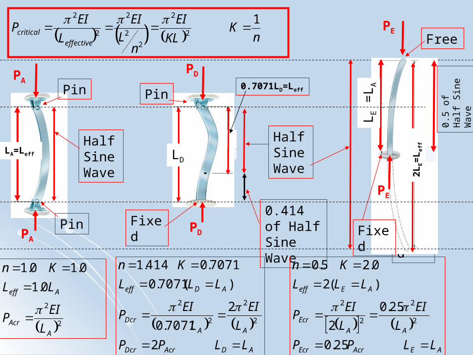
Half Sine Wave
Half Sine Wave
0.414 of Half Sine Wave
Pin
Pin
PD
22
0.1
0.10.1
A
Acr
Aeff
L
EIP
LL
Kn
ADAcrDcr
AA
Dcr
ADeff
LLPP
L
EI
L
EIP
LLL
Kn
2
2
7071.0
)(7071.0
7071.0414.1
2
2
2
2
AEAcrEcr
AA
Ecr
AEeff
LLPP
L
EI
L
EIP
LLL
Kn
25.0
25.0
2
)(2
0.25.0
2
2
2
2
LA=Leff
FixedFixed
Free
PA
PD
PE
PAFixed
LE =
L A
PE
Pin
LD
0.7071LD=Leff
2LE=
Le
ff
0.5
of H
alf
Sin
e W
ave

Elastic Buckling Theory – Ideal Column
ratiosslenderneseffectiver
KL
conditionsendiousforrKL
E
LK
Er
A
I
LK
E
A
IrGyrationofRadiusDefine
KL
EI
AArea
PStress
LoadBucklingatStresseDeter
BuckleCritical
BuckleCritical
criticalBuckleCritical
var/
:
1
:min
2
2
_
22
22
22
2
_
2
2
_
x
y
L
x=0 y=0
x=L y=0
nK
KL
EI
nL
EI
L
EIP
effective
critical
12
2
2
2
2
2
2

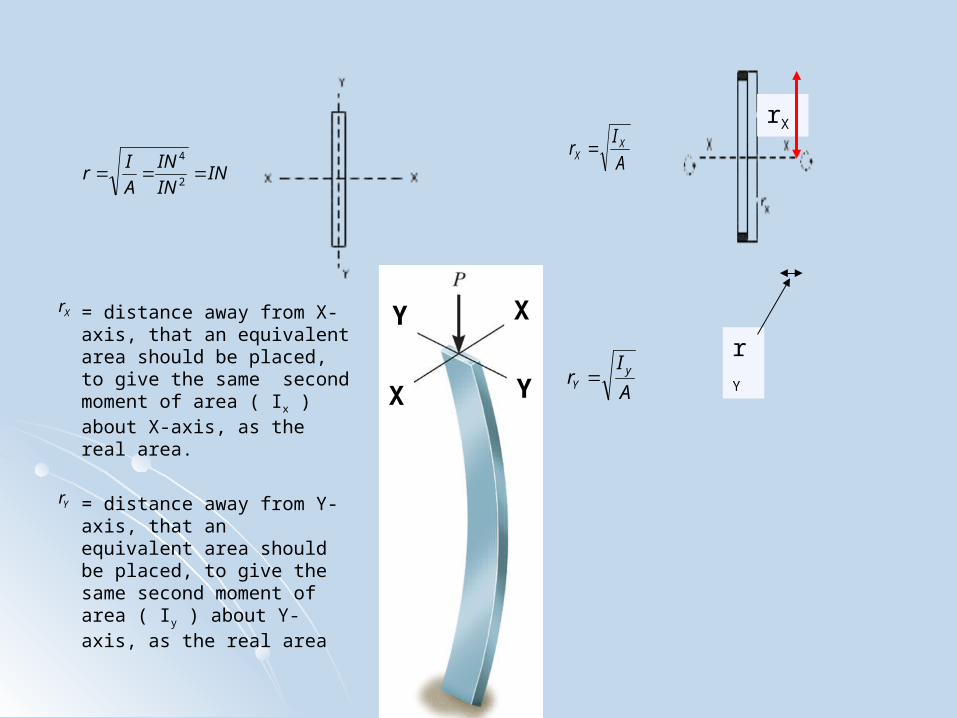
RADIUS OF GYRATIONB&J 8th, Section: 9.5
A
P
A
Ir
A
Ir Y
YX
X
σcrσcr
KL/r
2
22
2
_
KL
rE
rKL
EBuckleCritical
A
Ir yY
A
Ir XX
ININ
IN
A
Ir
2
4
Xr
Yr = distance away from Y-axis, that an equivalent area should be placed, to give the same second moment of area ( Iy ) about Y-axis, as the real area
= distance away from X-axis, that an equivalent area should be placed, to give the same second moment of area ( Ix ) about X-axis, as the real area.
rX
rY
X
X
Y
Y

Elastic Buckling – Ideal vs. Real Column123456789
10111213141516171819202122232425262728293031323334353637383940414243444546474849505152
A B C D E F G H I J K L M N O P Q
F-01-5 F-01-5 F-01-5 F-01-5 F-01-5 F-01-5 F-01-5 F-01-5 F-01-5 F-01-5 F-01-5 F-01-5 F-01-5 F-01-5 F-01-5 F-01-5
STEEL: Modulus of Elasticity = 2.90E+07 PSI STEEL: Yield Stress = 36 PSI
Moment Radius Buckling Buckling Buckling % Moment Radius BucklingEnd Column Column Column Column of of Slenderness Stress Load Stress Error of of Slenderness Stress
Conditions Length Width Thickness Area Inertia Gyration Ratio Theoretical Experimental Experimental Inertia Gyration Ratio Theoretical
K L B H A I R KL/r σcr P σexp (exp-thry)/thry I R KL/r σcrY axis Y axis Y axis Y axis Y axis Y axis X axis X axis X axis X axis
Pin-Pin buckling buckling buckling buckling buckling buckling buckling buckling(in.) (in.) (in.) (in.^2) (in.^4) (in.) (in./in.) (KSI) (Lb.) (KSI) (in.^4) (in.) (in./in.) (KSI)
INPUT INPUT INPUT INPUT INPUT1.0 6.0625 0.755 0.190 0.143 0.000432 0.0548 111 23.43 2950 20.56 -12% 0.006814 0.2179 28 369.921.0 8.0625 0.757 0.190 0.144 0.000433 0.0548 147 13.25 1900 13.21 0% 0.006868 0.2185 37 210.271.0 11.0625 0.750 0.198 0.149 0.000485 0.0572 194 7.64 1100 7.41 -3% 0.006961 0.2165 51 109.631.0 15.0000 0.759 0.192 0.146 0.000448 0.0554 271 3.91 500 3.43 -12% 0.006996 0.2191 68 61.071.0 18.0000 0.757 0.193 0.146 0.000454 0.0557 323 2.74 400 2.74 0% 0.006977 0.2185 82 42.19
F-01-5 F-01-5 F-01-5 F-01-5 F-01-5 F-01-5 F-01-5 F-01-5 F-01-5 F-01-5 F-01-5 F-01-5 F-01-5 F-01-5 F-01-5 F-01-5
Column Buckling, Pin-Pin, Steel, F-2001-Fall
0
5
10
15
20
25
0 50 100 150 200 250 300 350
Slenderness Ratio (KL/ry)
Bu
ckli
ng
Str
ess
(KS
I)
TheoreticalExperimental

Elastic Buckling Theory – Ideal Column
nK
KL
EI
nL
EI
L
EIP
effective
critical
12
2
2
2
2
2
2
PAcr Pcr = 4PAcr for L=LA
Pcr = 2PAcr for L=LA
Pcr=0.25PAcr for L=LA
L=LA
L=LA
LA L=LAL=LA
Leff=2L
Leff=0.5LLeff=0.7L