
1 BioUML - extensible workbench for systems biology Laboratory of Bioinformatics Novosibirsk,...
80
1 BioUML - extensible workbench for systems biology Laboratory of Bioinformatics Novosibirsk, Russia. www.itcsoftware.com 2004-2011 ITC Software All rights reserved.
-
Upload
patrick-ward -
Category
Documents
-
view
218 -
download
4
Transcript of 1 BioUML - extensible workbench for systems biology Laboratory of Bioinformatics Novosibirsk,...
1
BioUML - extensible workbench for systems biology
Laboratory of Bioinformatics
Novosibirsk, Russia.
www.itcsoftware.com
2004-2011 ITC Software All rights reserved.
2
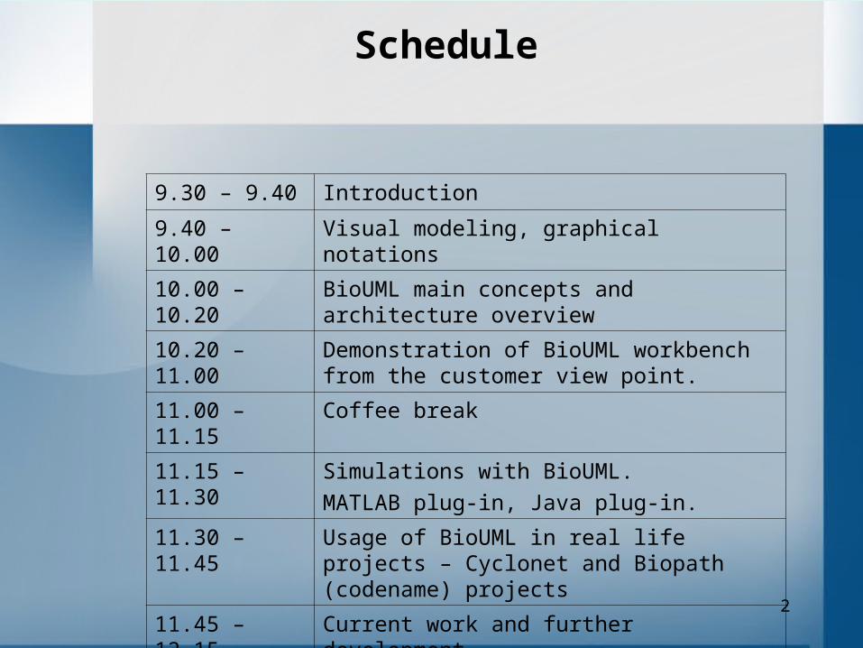
Schedule
9.30 – 9.40 Introduction
9.40 – 10.00 Visual modeling, graphical notations
10.00 – 10.20 BioUML main concepts and architecture overview
10.20 – 11.00 Demonstration of BioUML workbench from the customer view point.
11.00 – 11.15 Coffee break
11.15 – 11.30 Simulations with BioUML.
MATLAB plug-in, Java plug-in.
11.30 – 11.45 Usage of BioUML in real life projects – Cyclonet and Biopath (codename) projects
11.45 – 12.15 Current work and further development
12.15 – 12.30 Discussion
3
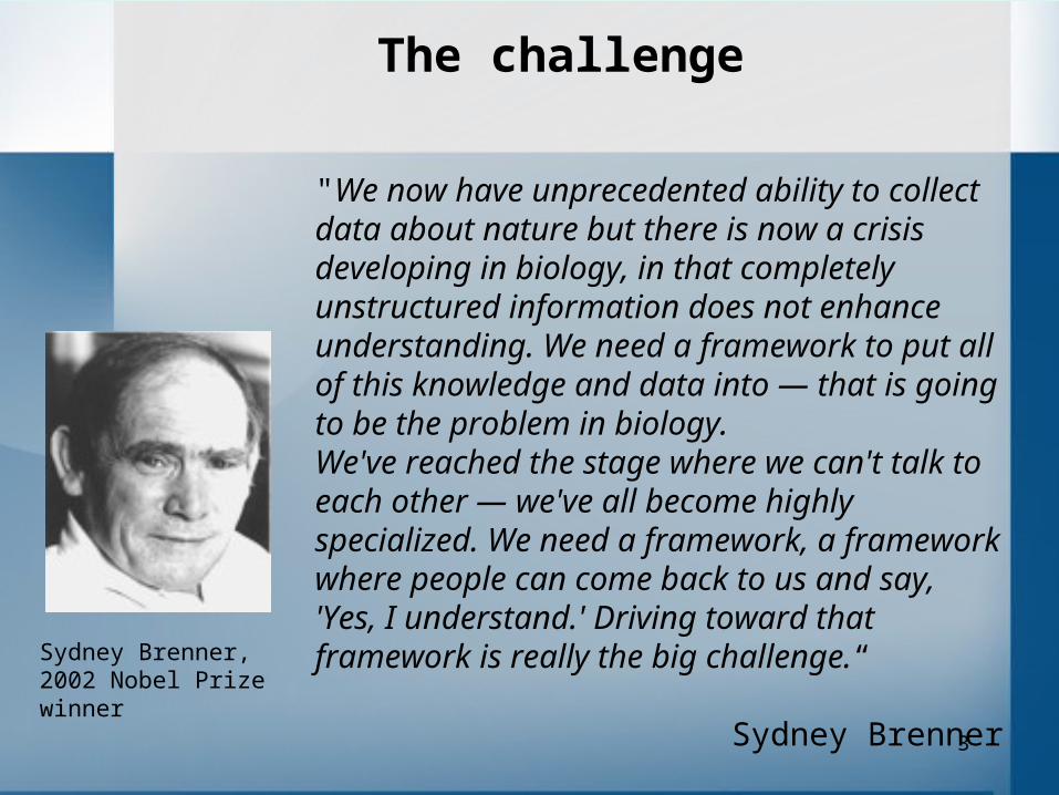
The challenge
"We now have unprecedented ability to collect data about nature but there is now a crisis developing in biology, in that completely unstructured information does not enhance understanding. We need a framework to put all of this knowledge and data into — that is going to be the problem in biology. We've reached the stage where we can't talk to each other — we've all become highly specialized. We need a framework, a framework where people can come back to us and say, 'Yes, I understand.' Driving toward that framework is really the big challenge.“
Sydney Brenner
Sydney Brenner, 2002 Nobel Prize winner
4

5
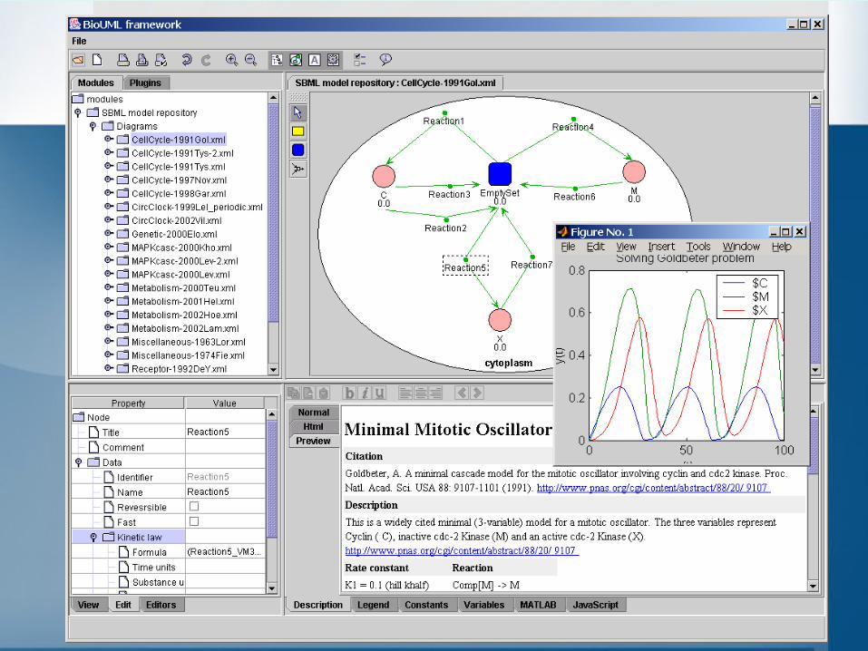
Main BioUML concepts and ideas
• Visual modeling• Plug-in based architecture (Eclipse platform runtime from
IBM).• Meta model – problem domain neutral level of abstraction
that describes system as compartmentalized graph. It is also common contract for all parties (software developers, problem domains specialists, annotators, mathematicians).
• Diagram type concept – formally defines graphical notation and provides its incorporation into BioUML workbench.
• Module concept - allows developer to incorporate databases on biological pathways into BioUML framework taking into account database peculiarities.
6
Visual Modeling
The problem of modeling and simulating of complex systems can be significantly simplified for customers by using computer systems providing visual modeling.
These visual depictions offer alternative syntax to completely and formally specify models.
A number of visual syntaxes were developed and implemented in computer systems for electrical engineering and computer science. The most known graphical language for computer science is UML – Unified Modeling Language.

7
The OMG specification states:
"The Unified Modeling Language (UML) is a graphical language for visualizing,specifying, constructing, and documenting the artifacts of a software-intensive system.
The UML offers a standard way to write a system's blueprints, including conceptualthings such as business processes and system functions as well as concrete things suchas programming language statements, database schemas, and reusable softwarecomponents."
8
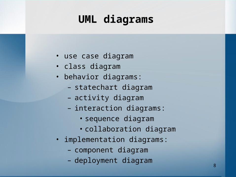
UML diagrams
• use case diagram
• class diagram
• behavior diagrams:
– statechart diagram
– activity diagram
– interaction diagrams:
• sequence diagram
• collaboration diagram
• implementation diagrams:
– component diagram
– deployment diagram

9
UML use case diagram
10
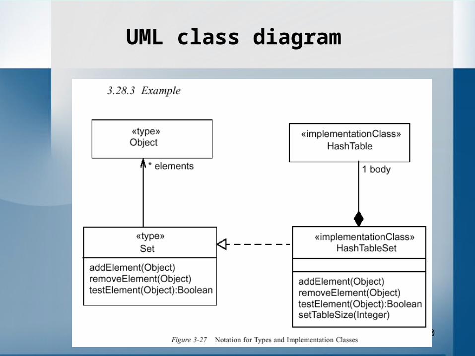
UML class diagram
11
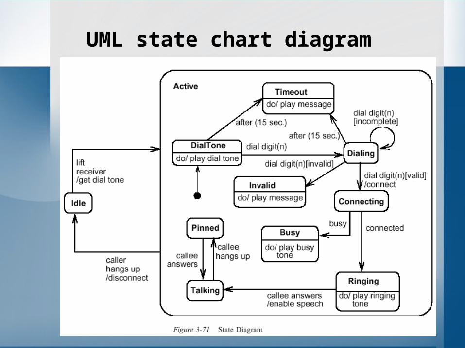
UML state chart diagram

12
UML activity diagram

13
UML sequence diagram

14
UML collaboration diagram
15
If we will consider UML architecture from developer view point then we will note:
1) UML was really designed for modeling software systems and are hardly suitable for other problem domains.
2) UML has complicated structure that is quite hard for implementation. OMG specification is more the 700 pages.
3) UML was not designed for visual modeling and simulation of dynamics of complex systems.
That is why we need new language for modeling biological systems and we called this language BioUML.
16
Graphical notations for biological pathways

17
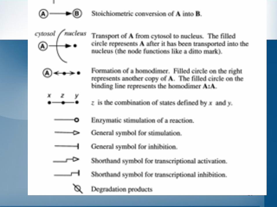
Some graphical notations for biological pathways
Kohn K.W. (1999). Molecular Interaction Map of the Mammalian Cell Cycle Control and DNA Repair Systems. Mol. Biol.Cell. 10, 2703-2734.Kitano H. (2003). A graphical notation for biochemical networks. BIOSILICO Vol. 1. No. 5.R. Maimon and S. Browning (2001). Diagrammatic Notation and Computational Grammar for Gene Networks. Proceedings of the International Conference on Systems Biology. 2001.Cook D.L. et al. (2001). A basis for a visual language for describing, archiving and analyzing functional models of complex biological systems. Genome Biol. 2. RESEARCH 0012.Database specific notations:- KEGG/Metabolic pathways; GeneNet system; TRANSPATH …

18
Kohn K.W. (1999). Molecular Interaction Map of the Mammalian Cell Cycle Control and DNA Repair Systems. Mol. Biol.Cell. 10, 2703-2734.
20
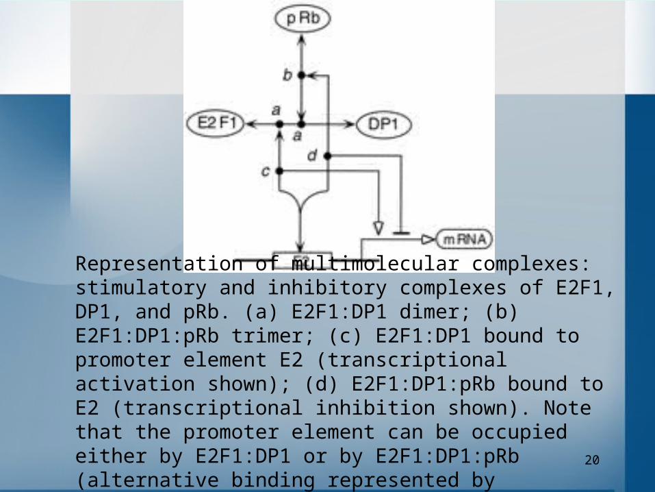
Representation of multimolecular complexes: stimulatory and inhibitory complexes of E2F1, DP1, and pRb. (a) E2F1:DP1 dimer; (b) E2F1:DP1:pRb trimer; (c) E2F1:DP1 bound to promoter element E2 (transcriptional activation shown); (d) E2F1:DP1:pRb bound to E2 (transcriptional inhibition shown). Note that the promoter element can be occupied either by E2F1:DP1 or by E2F1:DP1:pRb (alternative binding represented by interaction lines joined at an acute angle).

21

22
Kitano H. (2003). A graphical notation for biochemical networks. BIOSILICO Vol. 1. No. 5.
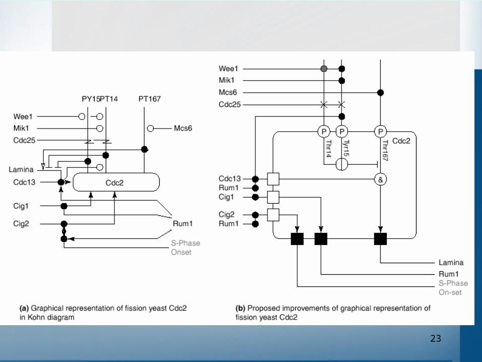
23

24
25
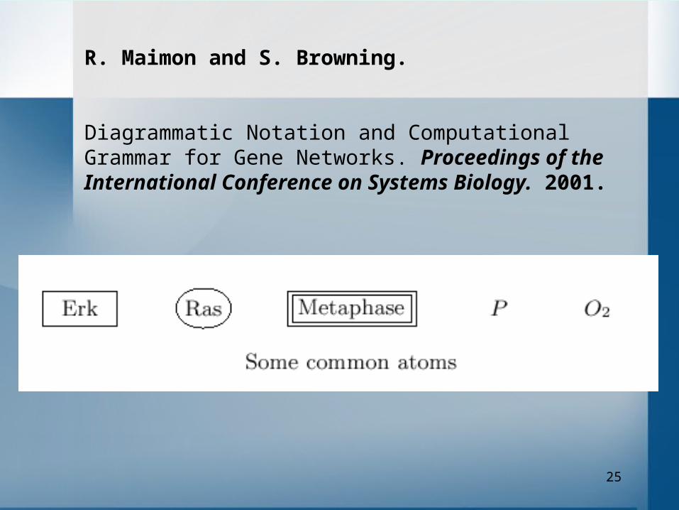
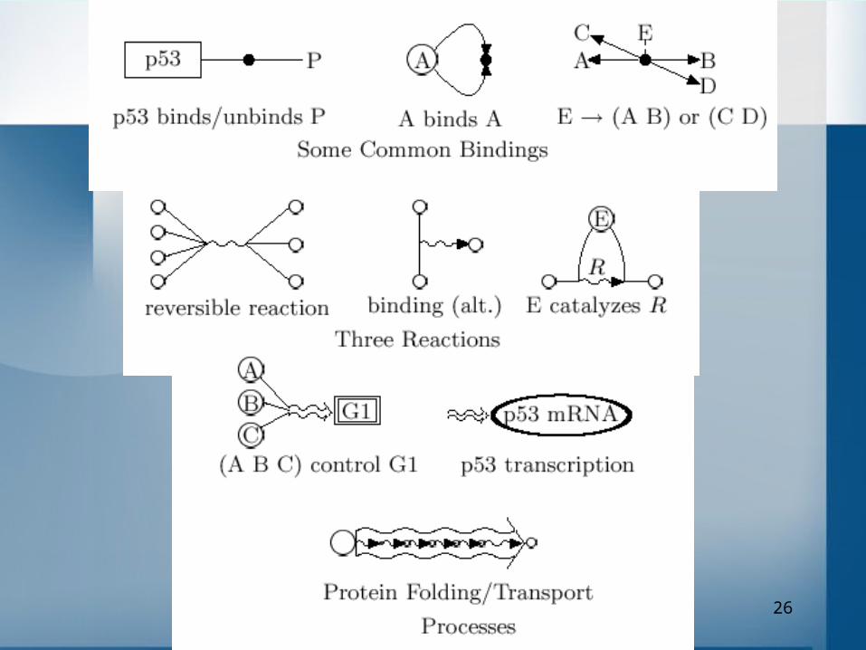
R. Maimon and S. Browning.
Diagrammatic Notation and Computational Grammar for Gene Networks. Proceedings of the International Conference on Systems Biology. 2001.
26
27
Formal description and modeling of biological systems require coordinated efforts of different group of researchers:
• programmers - they should provide computer tools for this task.
• problem domain experts - they should specify what and how should be described.
• experimenters and annotators - they should describe corresponding data following to these rules.
• mathematicians - they should provide methods for models analysis and simulations.
BioUML architecture separates these tasks so they can be effectively solved by corresponding group of researchers and provides simple contract how these groups and corresponding software parts should communicate.
28
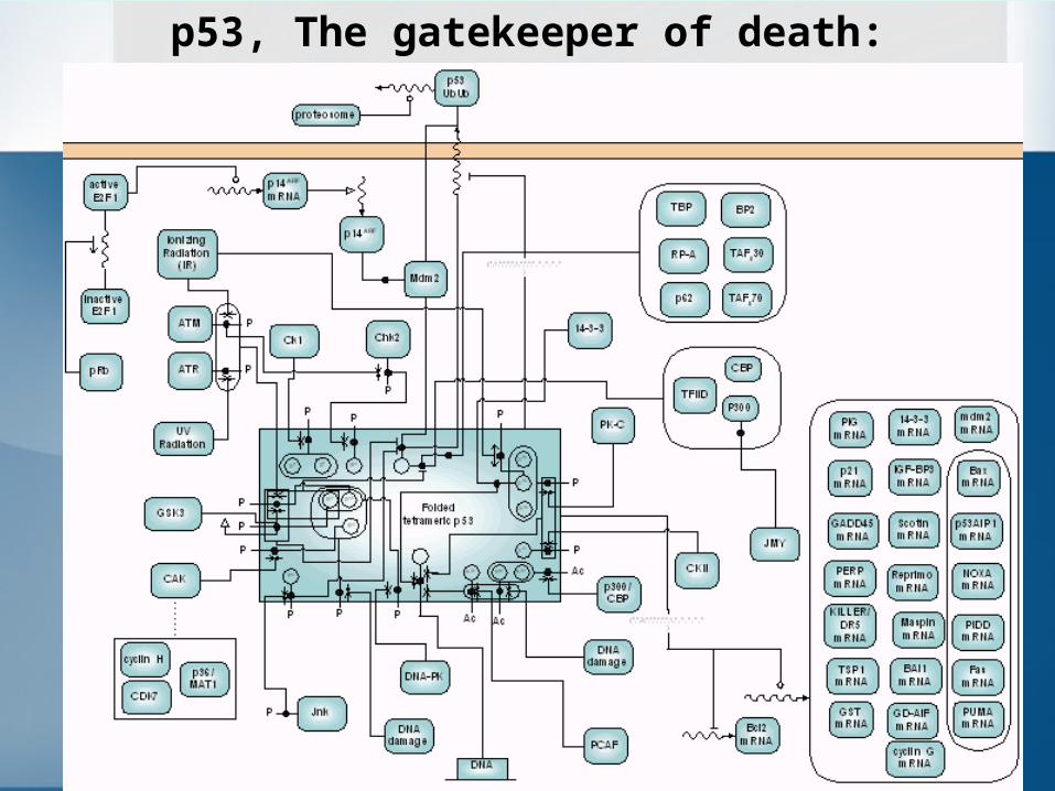
p53, The gatekeeper of death:
29
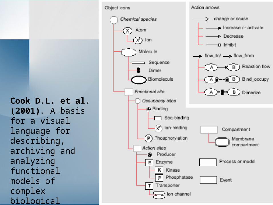
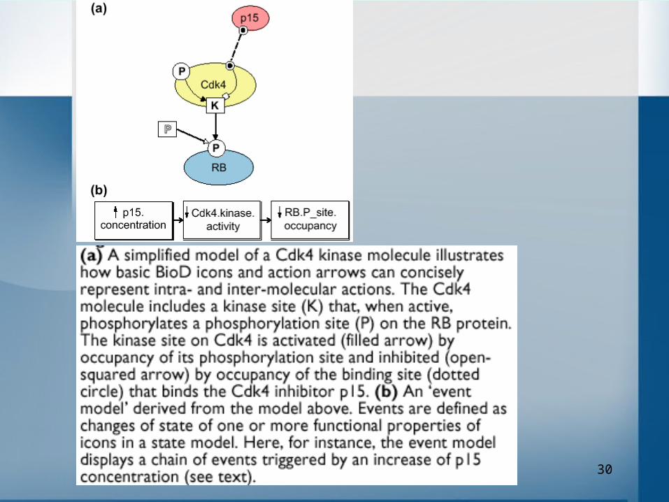
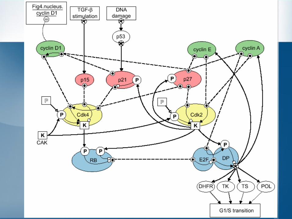
Cook D.L. et al. (2001). A basis for a visual language for describing, archiving and analyzing functional models of complex biological systems. Genome Biol. 2. RESEARCH 0012.
30
31

32
KEGG - metabolic pathways
33
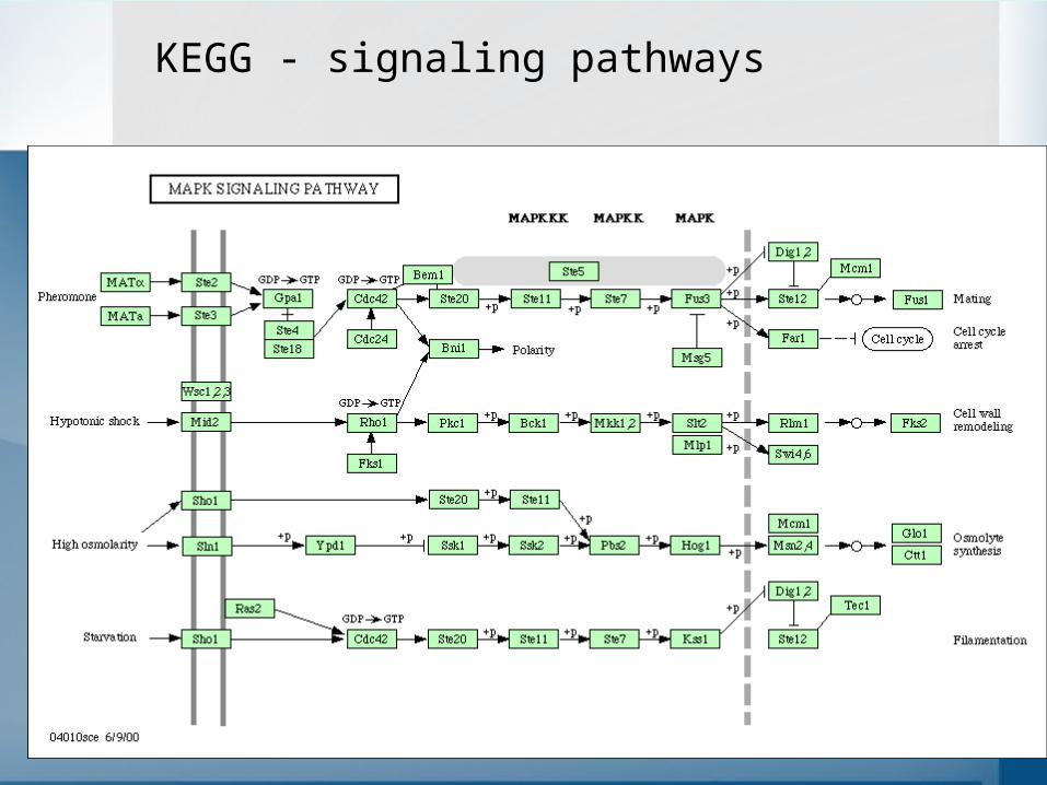
KEGG - signaling pathways
34
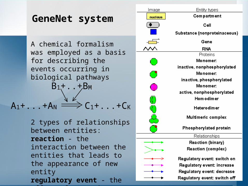
GeneNet system
B1+..+BM
A1+...+AN C1+...+CK
A chemical formalism was employed as a basis for describing the events occurring in biological pathways
2 types of relationships between entities:reaction - the interaction between the entities that leads to the appearance of new entityregulatory event - the effect of an entity on a certain reaction
35
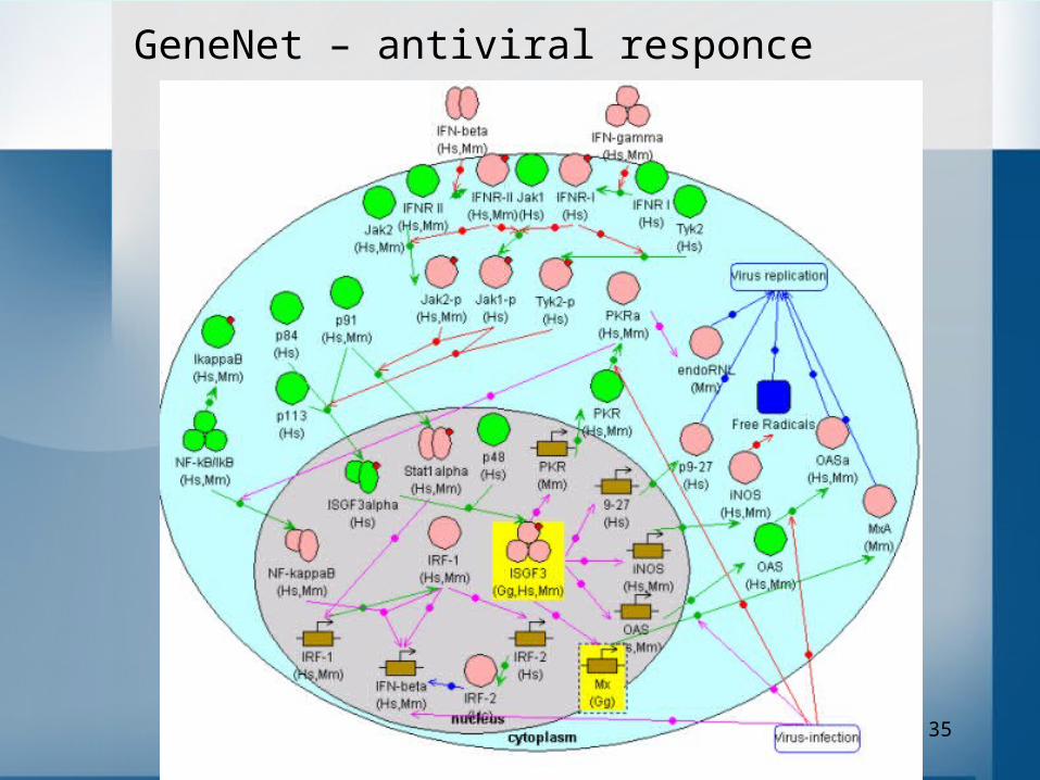
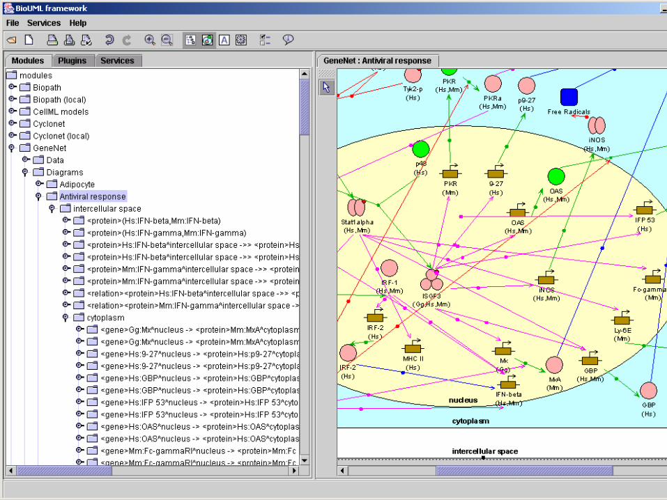
GeneNet – antiviral responce

36
TRANSPATH database

37
TRANSPATH – p53 pathway

38
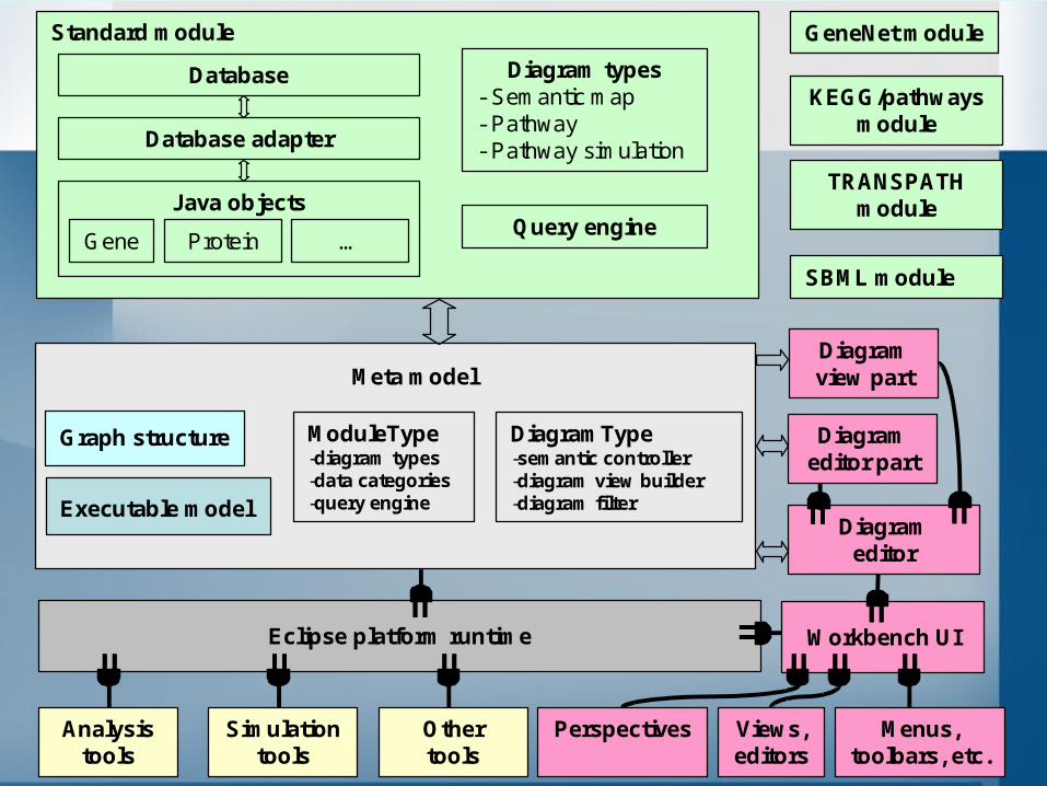
BioUML architecture

39
Plug-in based architecture
Plug-in- plugin.xml
- Java jar files
A plug-in is the smallest unit of BioUML workbench function that can be developed and delivered separately into BioUML workbench. A plug-in is described in an XML manifest file, called plugin.xml. The parsed contents of plug-in manifest files are made available programmatically through a plug-in registry API provided by Eclipse runtime. - extension points are well-defined function points in the system where other plug-ins can contribute functionality. - extension is a specific contribution to an extension point. Plug-ins can define their own extension points, so that other plug-ins can integrate tightly with them.
Plug-in - plugin.xml
- Java jar filesPlug-in
- plugin.xml- etc.
Eclipse platform runtime

40
Meta model
Executable model
Graph structure
Standard module
Database
Database adapter
Java objects
Gene Protein …
Diagram types- Semantic map- Pathway- Pathway simulation
Eclipse platform runtime Workbench UI
Diagram editor
Analysistools
Simulation tools
Other tools
Views, editors
Menus, toolbars, etc.
GeneNet module
KEGG/pathwaysmodule
TRANSPATHmodule
SBML module
Perspectives
Diagram view part
Diagram editor part
DiagramType-semantic controller-diagram view builder-diagram filter
ModuleType-diagram types-data categories-query engine
Query engine

41

42
43
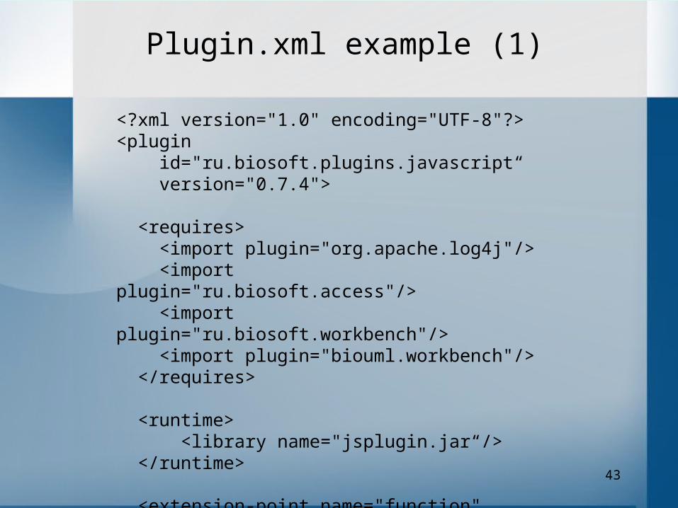
<?xml version="1.0" encoding="UTF-8"?><plugin id="ru.biosoft.plugins.javascript“ version="0.7.4"> <requires> <import plugin="org.apache.log4j"/> <import plugin="ru.biosoft.access"/> <import plugin="ru.biosoft.workbench"/> <import plugin="biouml.workbench"/> </requires>
<runtime> <library name="jsplugin.jar“/> </runtime>
<extension-point name="function" id="function"/> <extension-point name="function" id="hostObject"/>
Plugin.xml example (1)
44
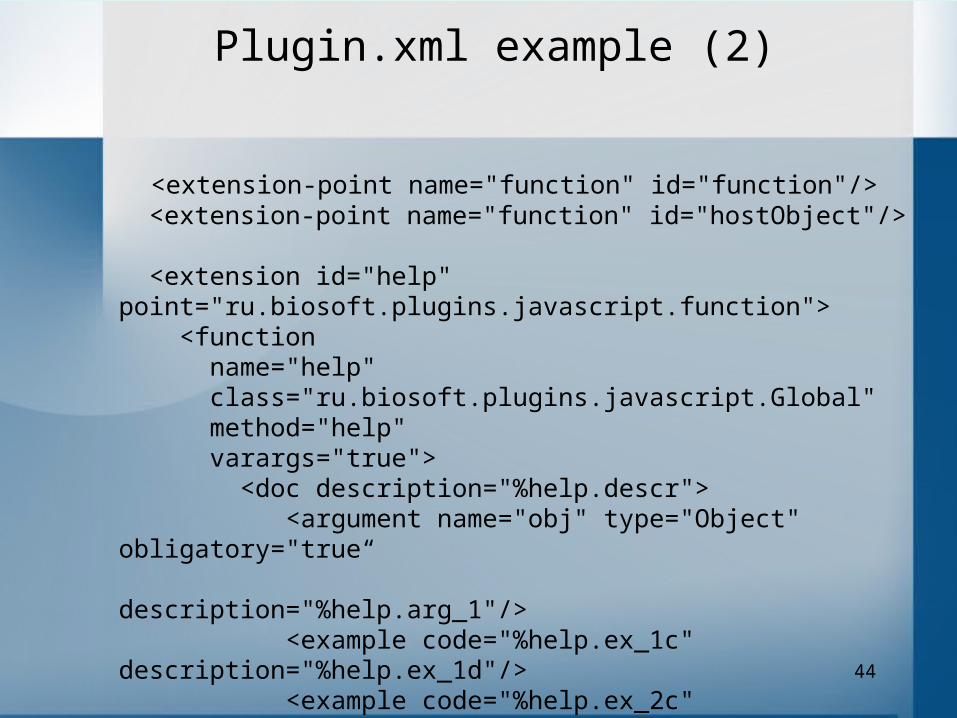
<extension-point name="function" id="function"/> <extension-point name="function" id="hostObject"/>
<extension id="help" point="ru.biosoft.plugins.javascript.function"> <function name="help" class="ru.biosoft.plugins.javascript.Global" method="help" varargs="true"> <doc description="%help.descr"> <argument name="obj" type="Object" obligatory="true“ description="%help.arg_1"/> <example code="%help.ex_1c" description="%help.ex_1d"/> <example code="%help.ex_2c" description="%help.ex_2d"/> <example code="%help.ex_3c" description="%help.ex_3d"/> </doc> </function> </extension>
Plugin.xml example (2)
45
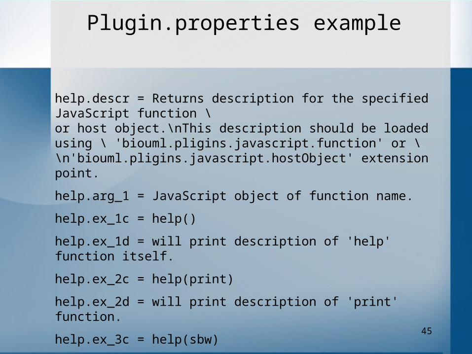
help.descr = Returns description for the specified JavaScript function \ or host object.\nThis description should be loaded using \ 'biouml.pligins.javascript.function' or \\n'biouml.pligins.javascript.hostObject' extension point.
help.arg_1 = JavaScript object of function name.
help.ex_1c = help()
help.ex_1d = will print description of 'help' function itself.
help.ex_2c = help(print)
help.ex_2d = will print description of 'print' function.
help.ex_3c = help(sbw)
help.ex_3d = will print description of sbw host object.
Plugin.properties example
46
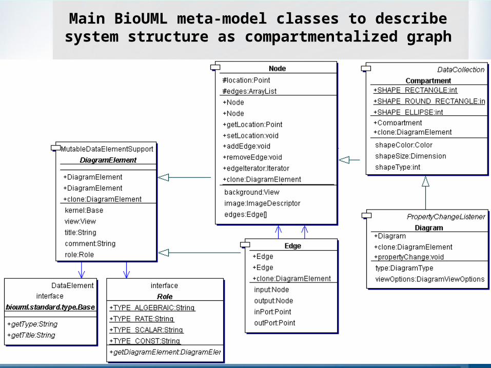
BioUML meta model
The core of BioUML workbench is meta model.
Unlike UML meta mode BioUML meta model is problem domain neutral and provides an abstract layer for comprehensive formal description of wide range of biological and other complex systems.
Content of databases on biological pathways or SBML models are expressed in terms of meta model and then can be used by other workbench plug-ins.

47
A Beq1 eq2
R1C
eq3 eq4
R2
1eqdt
dA
32 eqeqdt
dB
4eqdt
dC
Соответствующая ему математическая модель
Пример двух последовательных химических реакций
100 0 0
48
A B
-k1[A] k1[A]
R1 C
-k2[B] K2[B]
R2
100 0 0
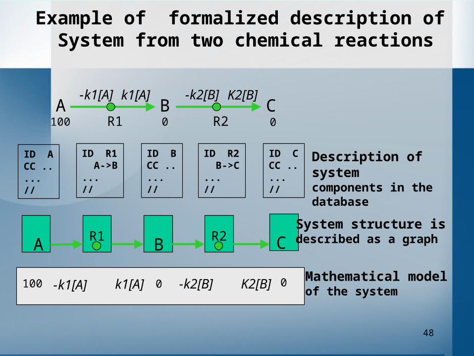
System structure is described as a graph
Mathematical model of the system
Description of system
components in the database
ID ACC .....//
ID R1A->B
...//
ID BCC .....//
ID R2B->C
...//
ID CCC .....//
A B-k1[A] k1[A]
R1C
-k2[B] K2[B]
R2100 0 0
Example of formalized description of System from two chemical reactions
49
Main BioUML meta-model classes to describe system structure as compartmentalized graph
50

51
52
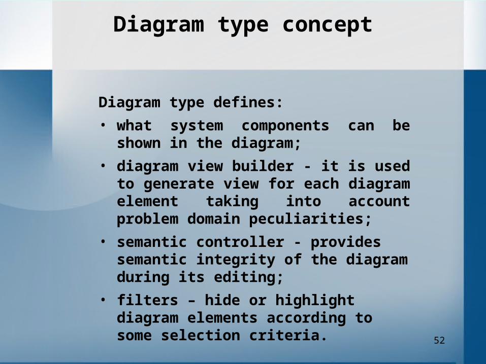
Diagram type concept
Diagram type defines:
• what system components can be shown in the diagram;
• diagram view builder - it is used to generate view for each diagram element taking into account problem domain peculiarities;
• semantic controller - provides semantic integrity of the diagram during its editing;
• filters – hide or highlight diagram elements according to some selection criteria.

53

54
Module Concept
• The module concept allows to developer define new diagram types and incorporate other databases on biological pathways into BioUML framework.
• The module defines mapping of database content into diagram elements and diagram types that can be used with the database.
• Module also provides query engine that can be used by BioUML workbench to find interactiong components of the system.

55
Modules
• standard BioUML module for biological pathways;
• module for models in SBML format;
• module for models in CellML format (only biochemical models);
• GeneNet database module;
• module for KEGG/Pathways datbase (draft);
• module for TRANSPATH database (draft);
• GeneOntology (under development).

56
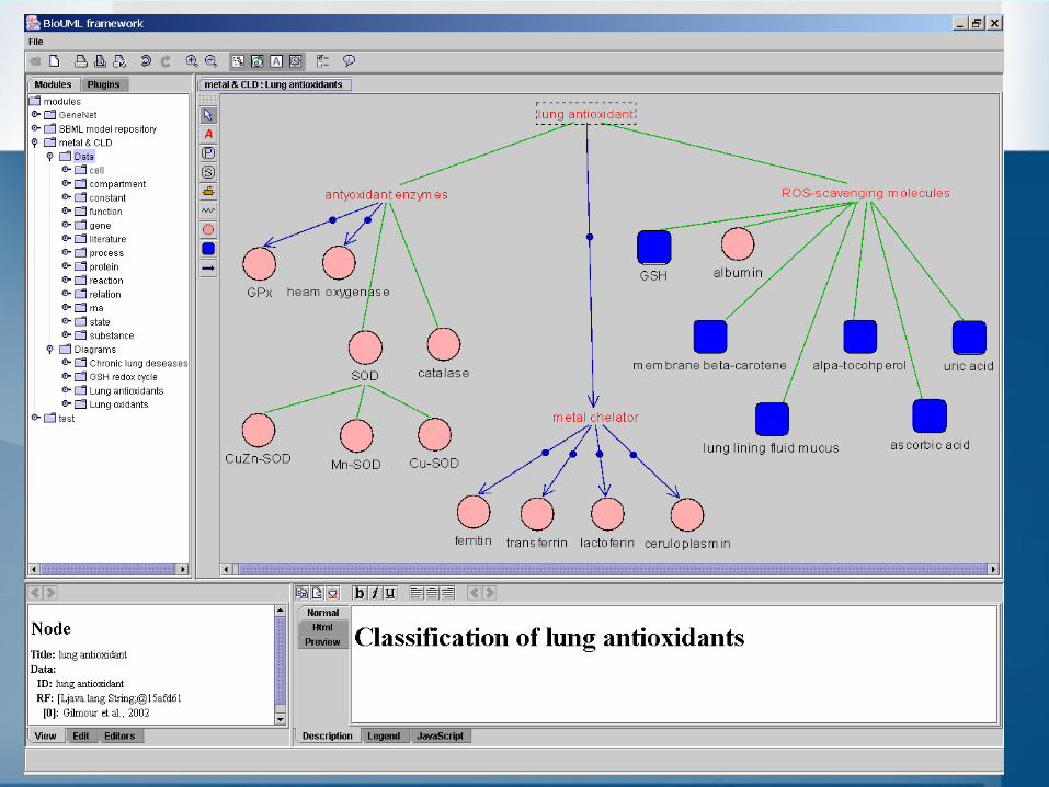
Standard BioUML module for biological pathways
The module defines most common biological data types (gene, protein, RNA, substance, reaction, etc.), they mapping into simple text database and three diagram types for description of biological pathways on several semantic levels:
1. Semantic network (ontology) - this diagram type is used to describe semantic relationships between system components, system states, and related problem domain concepts.
2. Pathway diagram type is used for formalized description of biological pathway structure. This diagram type uses GeneNet graphical notation.
3. Pathway simulation diagram type is extension of pathway structure diagram, where variables are associated with graph nodes and differential equations with graph edges. This allows to BioUML workbench automatically generate mathematical model of the system and simulate its dynamics.
57
58

59
60
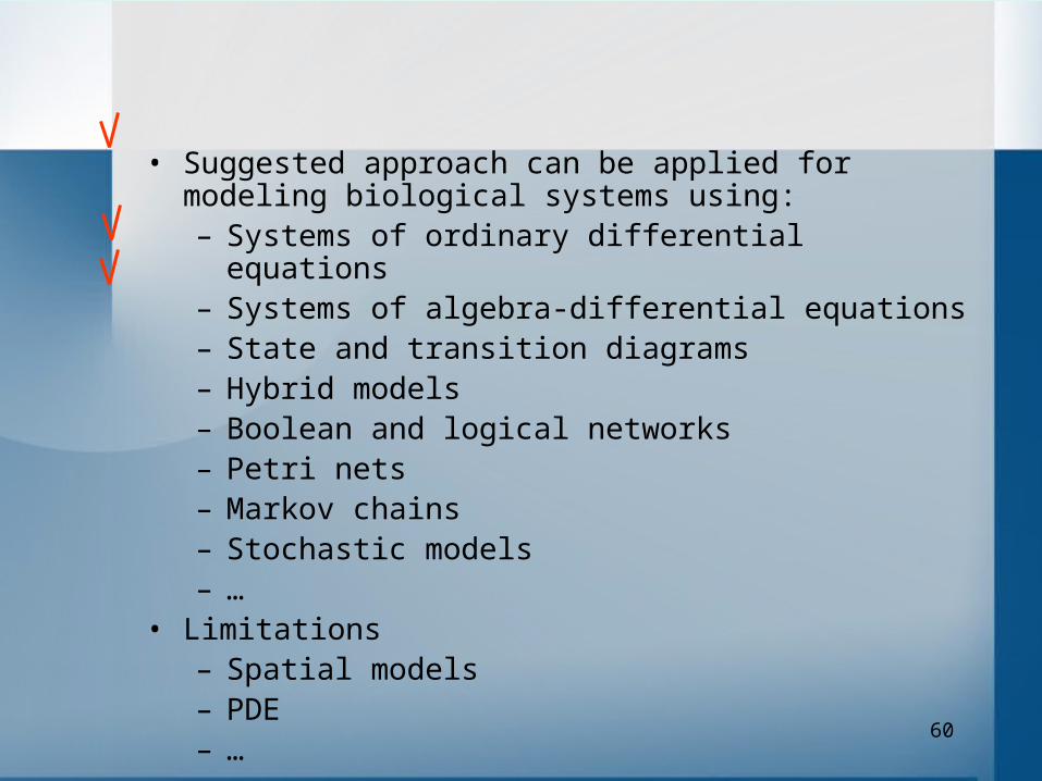
• Suggested approach can be applied for modeling biological systems using:– Systems of ordinary differential equations– Systems of algebra-differential equations– State and transition diagrams– Hybrid models– Boolean and logical networks– Petri nets– Markov chains– Stochastic models– …
• Limitations– Spatial models– PDE– …
61
Meta model
Executable model
Graph structure
Standard module
Database
Database adapter
Java objects
Gene Protein …
Diagram types- Semantic map- Pathway- Pathway simulation
Eclipse platform runtime Workbench UI
Diagram editor
Analysistools
Simulation tools
Other tools
Views, editors
Menus, toolbars, etc.
GeneNet module
KEGG/pathwaysmodule
TRANSPATHmodule
SBML module
Perspectives
Diagram view part
Diagram editor part
DiagramType-semantic controller-diagram view builder-diagram filter
ModuleType-diagram types-data categories-query engine
Query engine
62
Formal description and modeling of biological systems require coordinated efforts of different group of researchers:
• programmers - they should provide computer tools for this task.
• problem domain experts - they should specify what and how should be described.
• experimenters and annotators - they should describe corresponding data following to these rules.
• mathematicians - they should provide methods for models analysis and simulations.
BioUML architecture separates these tasks so they can be effectively solved by corresponding group of researchers and provides simple contract how these groups and corresponding software parts should communicate.
63
BioUML live demonstration
64
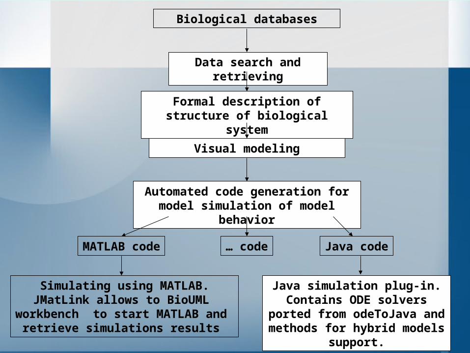
Biological databases
Data search and retrieving
Visual modeling
Automated code generation for model simulation of model behavior
Formal description of structure of biological system
MATLAB code Java code
Simulating using MATLAB.JMatLink allows to BioUML
workbench to start MATLAB and retrieve simulations results
Java simulation plug-in.Contains ODE solvers ported from odeToJava and methods
for hybrid models support.
… code
65
Cyclonet database
66
Cyclonet database
Using BioUML workbench we are developing Cyclonet database – a database on cell cycle regulation in eukaryotes. Using BeanExplorer Enterprise Edition database content is available via the Internet.
The database contains information about cell cycle specific genes, proteins, protein complexes and their interactions, diagrams of cell cycle regulation for vertebrates, models of cell cycle and results of their analyses, microarray data, literature references and other related resources.
67
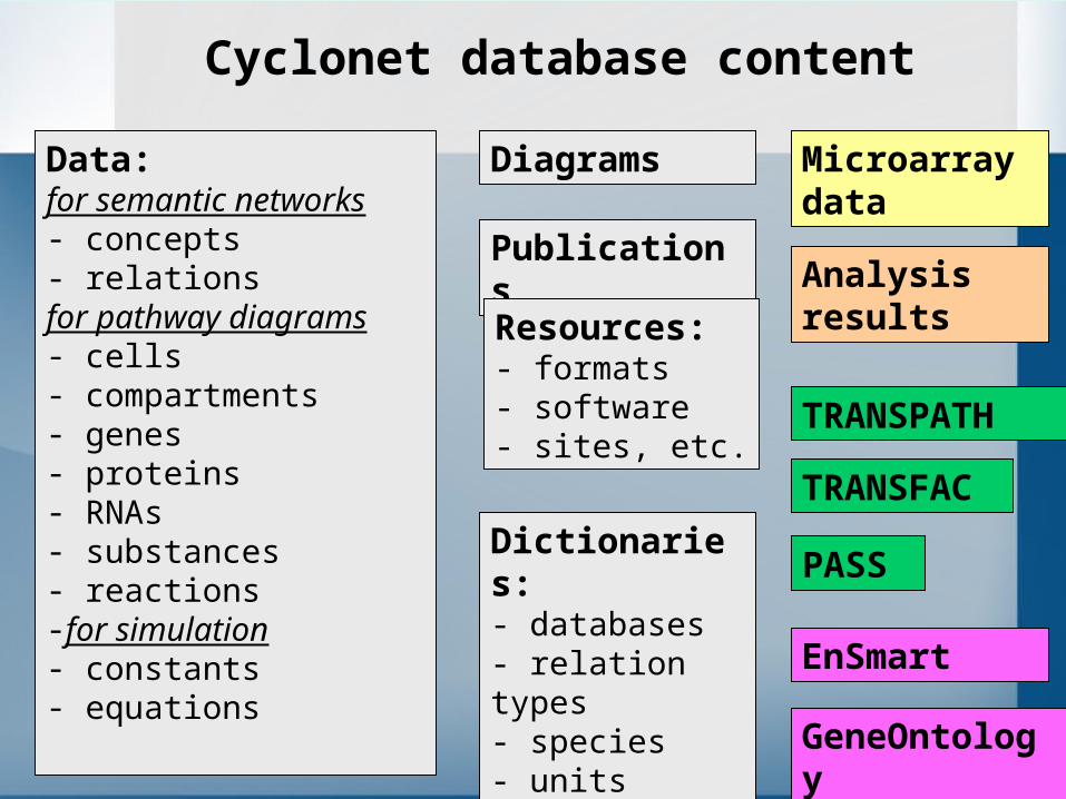
Cyclonet database content
Data:for semantic networks- concepts- relations for pathway diagrams- cells- compartments- genes- proteins- RNAs- substances- reactions-for simulation- constants- equations
Dictionaries:- databases- relation types- species- units- constants
Publications
Resources:- formats- software- sites, etc.
Diagrams Microarray data
Analysis results
EnSmart
GeneOntology
TRANSPATH
TRANSFAC
PASS
68
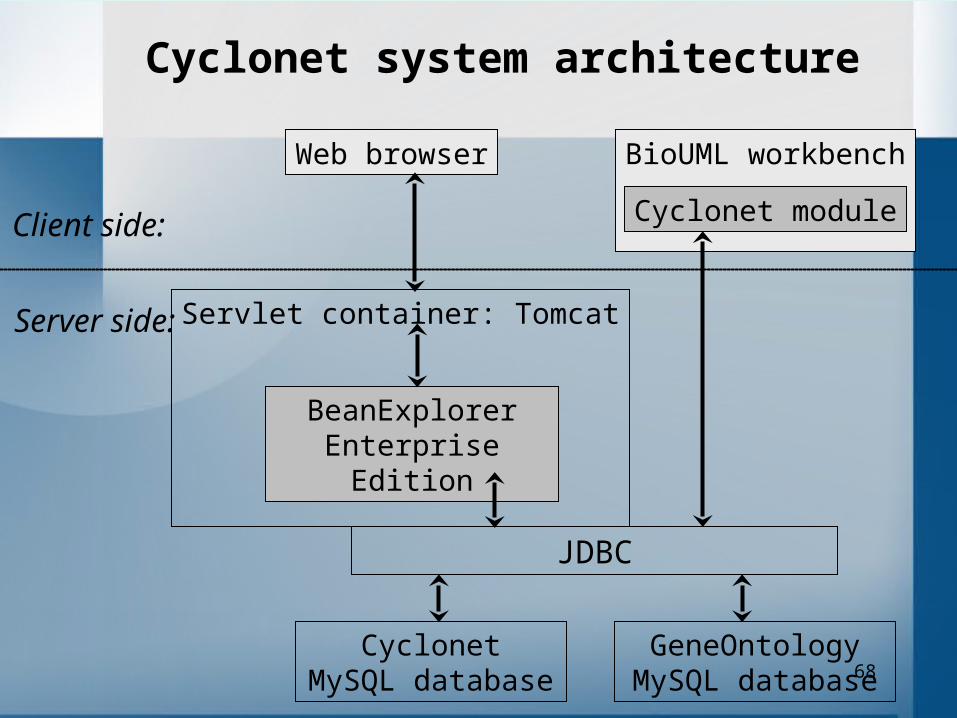
BioUML workbench
Servlet container: Tomcat
Cyclonet system architecture
CyclonetMySQL database
Web browser
JDBC
BeanExplorerEnterprise Edition
Client side:
Server side:
Cyclonet module
GeneOntologyMySQL database

69

70
71
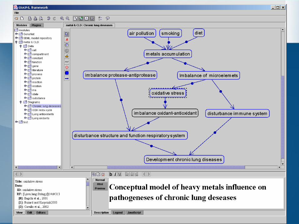
Biopath (codename) database
Purpose of this project is create formal description of pathogeneses of chronic respiratory diseases and optimization of their treatment.
The work is performed jointly with the Institute of Medical Problems of North (Krasnoyarsk) and the Institute of Pulmonology (Moscow).
72
• Graph search engine– Graph search engine completion and testing– adaptation of new graph layout library
• Complete support of SBML level 2 – Time delay– Algebraic rules– Units– SBML semantic tests
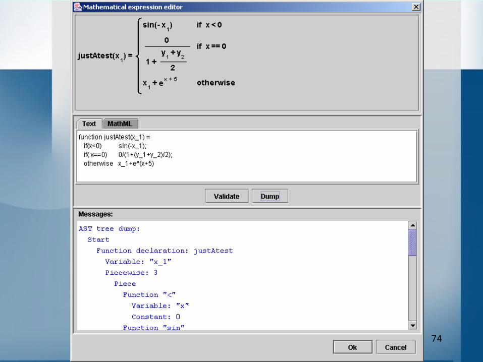
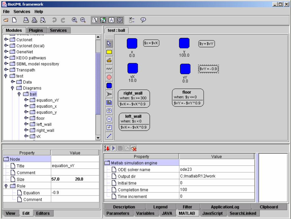
• Formula editor• State and transition diagrams.
Current work
73
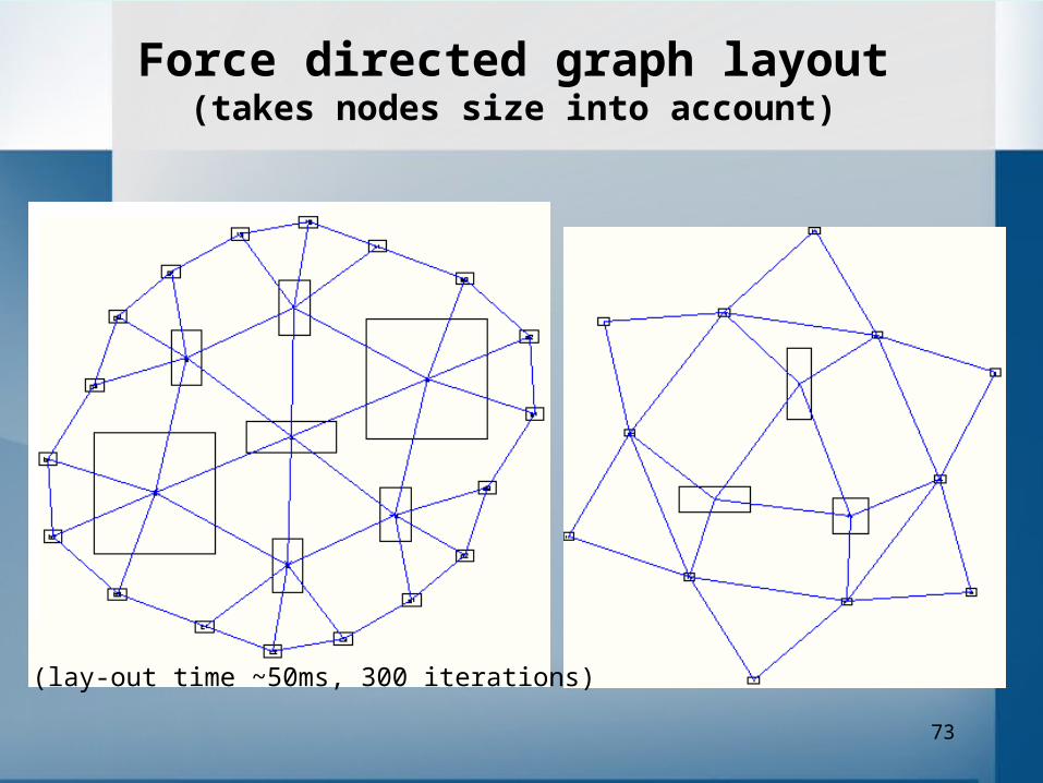
Force directed graph layout(takes nodes size into account)
(lay-out time ~50ms, 300 iterations)
74
75

76
77
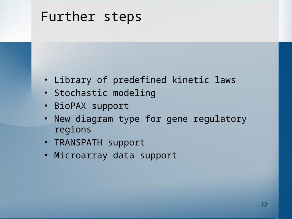
• Library of predefined kinetic laws
• Stochastic modeling
• BioPAX support
• New diagram type for gene regulatory regions
• TRANSPATH support
• Microarray data support
Further steps
78
Availability
BioUML workbench (including source code) is freely available at www.itcsoftware.com
Cyclonet database } see site Biopath database } for details

79
Acknowledgments
Part of this work was partially supported by following grants: Volkswagen-Stiftung (I/75941), INTAS Nr. 03-51-5218 and RFBR Nr. 04-04-49826-а.
Author is grateful to for useful comments, discussions and technical support
Alexander Kel Sergey Zhatchenko
Software developers Annotators
Mikhail Puzanov Igor Tyazhev Ruslan Sharipov Vasiliy Hudyakov Vlad Zhvaleev Elena Cheremushkina Alexandr Koshukov Oleg Onegov Artem Shaidukov

80
ITC Software is an advanced information technology solutions provider, focused on the global commercial and scientific markets.
With over 4047 software engineers in the Americas, Europe, Russia and Asia, and a host of world-renowned scientists at, inter alia, Harvard and MIT, ITC Software’s services range from research & development in finance, bioinformatics and FEA engineering, to cutting-edge custom software development and maintenance services in most industry verticals, to the turnkey establishment of Offshore IT Centers.
ITC Software has won numerous international awards and its centers are ISO 9001:2000 certified and CMMI level 4 pre-certified. Pricing is extremely competitive for both complex scientific applications such as bioinformatics and biomechanics, and commercial software development projects.
We hope you enjoyed our presentation !
Please call or email us, if you have any questions, need more information, would like to embark on a research project, or require software development servicesTel. +1 978 287 [email protected]
Become a high performance enterprise with Strategic Outsourcing, visit www.itcsoftware.com
Thank you!
About I TC Software