1 Approximate Radix-8 Booth Multipliers for Low-Power...
8
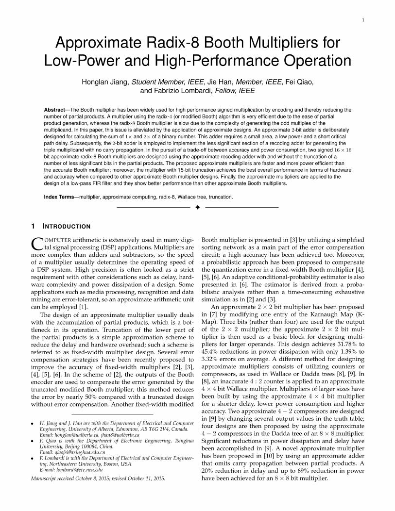
1 Approximate Radix-8 Booth Multipliers for Low-Power and High-Performance Operation Honglan Jiang, Student Member, IEEE, Jie Han, Member, IEEE, Fei Qiao, and Fabrizio Lombardi, Fellow, IEEE Abstract—The Booth multiplier has been widely used for high performance signed multiplication by encoding and thereby reducing the number of partial products. A multiplier using the radix-4 (or modified Booth) algorithm is very efficient due to the ease of partial product generation, whereas the radix-8 Booth multiplier is slow due to the complexity of generating the odd multiples of the multiplicand. In this paper, this issue is alleviated by the application of approximate designs. An approximate 2-bit adder is deliberately designed for calculating the sum of 1× and 2× of a binary number. This adder requires a small area, a low power and a short critical path delay. Subsequently, the 2-bit adder is employed to implement the less significant section of a recoding adder for generating the triple multiplicand with no carry propagation. In the pursuit of a trade-off between accuracy and power consumption, two signed 16 × 16 bit approximate radix-8 Booth multipliers are designed using the approximate recoding adder with and without the truncation of a number of less significant bits in the partial products. The proposed approximate multipliers are faster and more power efficient than the accurate Booth multiplier; moreover, the multiplier with 15-bit truncation achieves the best overall performance in terms of hardware and accuracy when compared to other approximate Booth multiplier designs. Finally, the approximate multipliers are applied to the design of a low-pass FIR filter and they show better performance than other approximate Booth multipliers. Index Terms—multiplier, approximate computing, radix-8, Wallace tree, truncation. ✦ 1 I NTRODUCTION C OMPUTER arithmetic is extensively used in many digi- tal signal processing (DSP) applications. Multipliers are more complex than adders and subtractors, so the speed of a multiplier usually determines the operating speed of a DSP system. High precision is often looked as a strict requirement with other considerations such as delay, hard- ware complexity and power dissipation of a design. Some applications such as media processing, recognition and data mining are error-tolerant, so an approximate arithmetic unit can be employed [1]. The design of an approximate multiplier usually deals with the accumulation of partial products, which is a bot- tleneck in its operation. Truncation of the lower part of the partial products is a simple approximation scheme to reduce the delay and hardware overhead; such a scheme is referred to as fixed-width multiplier design. Several error compensation strategies have been recently proposed to improve the accuracy of fixed-width multipliers [2], [3], [4], [5], [6]. In the scheme of [2], the outputs of the Booth encoder are used to compensate the error generated by the truncated modified Booth multiplier; this method reduces the error by nearly 50% compared with a truncated design without error compensation. Another fixed-width modified • H. Jiang and J. Han are with the Department of Electrical and Computer Engineering, University of Alberta, Edmonton, AB T6G 2V4, Canada. Email: [email protected], [email protected] • F. Qiao is with the Department of Electronic Engineering, Tsinghua University, Beijing 100084, China. Email: [email protected] • F. Lombardi is with the Department of Electrical and Computer Engineer- ing, Northeastern University, Boston, USA. E-mail: [email protected] Manuscript received October 8, 2015; revised October 11, 2015. Booth multiplier is presented in [3] by utilizing a simplified sorting network as a main part of the error compensation circuit; a high accuracy has been achieved too. Moreover, a probabilistic approach has been proposed to compensate the quantization error in a fixed-width Booth multiplier [4], [5], [6]. An adaptive conditional-probability estimator is also presented in [6]. The estimator is derived from a proba- bilistic analysis rather than a time-consuming exhaustive simulation as in [2] and [3]. An approximate 2 × 2 bit multiplier has been proposed in [7] by modifying one entry of the Karnaugh Map (K- Map). Three bits (rather than four) are used for the output of the 2 × 2 multiplier; the approximate 2 × 2 bit mul- tiplier is then used as a basic block for designing multi- pliers for larger operands. This design achieves 31.78% to 45.4% reductions in power dissipation with only 1.39% to 3.32% errors on average. A different method for designing approximate multipliers consists of utilizing counters or compressors, as used in Wallace or Dadda trees [8], [9]. In [8], an inaccurate 4:2 counter is applied to an approximate 4 × 4 bit Wallace multiplier. Multipliers of larger sizes have been built by using the approximate 4 × 4 bit multiplier for a shorter delay, lower power consumption and higher accuracy. Two approximate 4 - 2 compressors are designed in [9] by changing several output values in the truth table; four designs are then proposed by using the approximate 4 - 2 compressors in the Dadda tree of an 8 × 8 multiplier. Significant reductions in power dissipation and delay have been accomplished in [9]. A novel approximate multiplier has been proposed in [10] by using an approximate adder that omits carry propagation between partial products. A 20% reduction in delay and up to 69% reduction in power have been achieved for an 8 × 8 bit multiplier.
-
Upload
duongduong -
Category
Documents
-
view
226 -
download
0
Transcript of 1 Approximate Radix-8 Booth Multipliers for Low-Power...
1
Approximate Radix-8 Booth Multipliers forLow-Power and High-Performance Operation
Honglan Jiang, Student Member, IEEE, Jie Han, Member, IEEE, Fei Qiao,and Fabrizio Lombardi, Fellow, IEEE
Abstract—The Booth multiplier has been widely used for high performance signed multiplication by encoding and thereby reducing thenumber of partial products. A multiplier using the radix-4 (or modified Booth) algorithm is very efficient due to the ease of partialproduct generation, whereas the radix-8 Booth multiplier is slow due to the complexity of generating the odd multiples of themultiplicand. In this paper, this issue is alleviated by the application of approximate designs. An approximate 2-bit adder is deliberatelydesigned for calculating the sum of 1× and 2× of a binary number. This adder requires a small area, a low power and a short criticalpath delay. Subsequently, the 2-bit adder is employed to implement the less significant section of a recoding adder for generating thetriple multiplicand with no carry propagation. In the pursuit of a trade-off between accuracy and power consumption, two signed 16× 16
bit approximate radix-8 Booth multipliers are designed using the approximate recoding adder with and without the truncation of anumber of less significant bits in the partial products. The proposed approximate multipliers are faster and more power efficient thanthe accurate Booth multiplier; moreover, the multiplier with 15-bit truncation achieves the best overall performance in terms of hardwareand accuracy when compared to other approximate Booth multiplier designs. Finally, the approximate multipliers are applied to thedesign of a low-pass FIR filter and they show better performance than other approximate Booth multipliers.
Index Terms—multiplier, approximate computing, radix-8, Wallace tree, truncation.
F
1 INTRODUCTION
COMPUTER arithmetic is extensively used in many digi-tal signal processing (DSP) applications. Multipliers are
more complex than adders and subtractors, so the speedof a multiplier usually determines the operating speed ofa DSP system. High precision is often looked as a strictrequirement with other considerations such as delay, hard-ware complexity and power dissipation of a design. Someapplications such as media processing, recognition and datamining are error-tolerant, so an approximate arithmetic unitcan be employed [1].
The design of an approximate multiplier usually dealswith the accumulation of partial products, which is a bot-tleneck in its operation. Truncation of the lower part ofthe partial products is a simple approximation scheme toreduce the delay and hardware overhead; such a scheme isreferred to as fixed-width multiplier design. Several errorcompensation strategies have been recently proposed toimprove the accuracy of fixed-width multipliers [2], [3],[4], [5], [6]. In the scheme of [2], the outputs of the Boothencoder are used to compensate the error generated by thetruncated modified Booth multiplier; this method reducesthe error by nearly 50% compared with a truncated designwithout error compensation. Another fixed-width modified
• H. Jiang and J. Han are with the Department of Electrical and ComputerEngineering, University of Alberta, Edmonton, AB T6G 2V4, Canada.Email: [email protected], [email protected]
• F. Qiao is with the Department of Electronic Engineering, TsinghuaUniversity, Beijing 100084, China.Email: [email protected]
• F. Lombardi is with the Department of Electrical and Computer Engineer-ing, Northeastern University, Boston, USA.E-mail: [email protected]
Manuscript received October 8, 2015; revised October 11, 2015.
Booth multiplier is presented in [3] by utilizing a simplifiedsorting network as a main part of the error compensationcircuit; a high accuracy has been achieved too. Moreover,a probabilistic approach has been proposed to compensatethe quantization error in a fixed-width Booth multiplier [4],[5], [6]. An adaptive conditional-probability estimator is alsopresented in [6]. The estimator is derived from a proba-bilistic analysis rather than a time-consuming exhaustivesimulation as in [2] and [3].
An approximate 2 × 2 bit multiplier has been proposedin [7] by modifying one entry of the Karnaugh Map (K-Map). Three bits (rather than four) are used for the outputof the 2 × 2 multiplier; the approximate 2 × 2 bit mul-tiplier is then used as a basic block for designing multi-pliers for larger operands. This design achieves 31.78% to45.4% reductions in power dissipation with only 1.39% to3.32% errors on average. A different method for designingapproximate multipliers consists of utilizing counters orcompressors, as used in Wallace or Dadda trees [8], [9]. In[8], an inaccurate 4 : 2 counter is applied to an approximate4× 4 bit Wallace multiplier. Multipliers of larger sizes havebeen built by using the approximate 4 × 4 bit multiplierfor a shorter delay, lower power consumption and higheraccuracy. Two approximate 4− 2 compressors are designedin [9] by changing several output values in the truth table;four designs are then proposed by using the approximate4 − 2 compressors in the Dadda tree of an 8 × 8 multiplier.Significant reductions in power dissipation and delay havebeen accomplished in [9]. A novel approximate multiplierhas been proposed in [10] by using an approximate adderthat omits carry propagation between partial products. A20% reduction in delay and up to 69% reduction in powerhave been achieved for an 8× 8 bit multiplier.
2
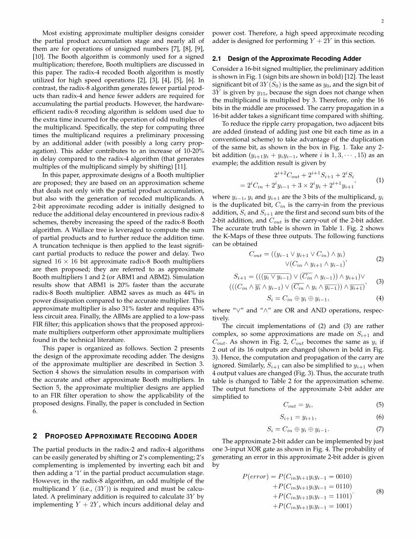
Most existing approximate multiplier designs considerthe partial product accumulation stage and nearly all ofthem are for operations of unsigned numbers [7], [8], [9],[10]. The Booth algorithm is commonly used for a signedmultiplication; therefore, Booth multipliers are discussed inthis paper. The radix-4 recoded Booth algorithm is mostlyutilized for high speed operations [2], [3], [4], [5], [6]. Incontrast, the radix-8 algorithm generates fewer partial prod-ucts than radix-4 and hence fewer adders are required foraccumulating the partial products. However, the hardware-efficient radix-8 recoding algorithm is seldom used due tothe extra time incurred for the operation of odd multiples ofthe multiplicand. Specifically, the step for computing threetimes the multiplicand requires a preliminary processingby an additional adder (with possibly a long carry prop-agation). This adder contributes to an increase of 10-20%in delay compared to the radix-4 algorithm (that generatesmultiples of the multiplicand simply by shifting) [11].
In this paper, approximate designs of a Booth multiplierare proposed; they are based on an approximation schemethat deals not only with the partial product accumulation,but also with the generation of recoded multiplicands. A2-bit approximate recoding adder is initially designed toreduce the additional delay encountered in previous radix-8schemes, thereby increasing the speed of the radix-8 Boothalgorithm. A Wallace tree is leveraged to compute the sumof partial products and to further reduce the addition time.A truncation technique is then applied to the least signifi-cant partial products to reduce the power and delay. Twosigned 16 × 16 bit approximate radix-8 Booth multipliersare then proposed; they are referred to as approximateBooth multipliers 1 and 2 (or ABM1 and ABM2). Simulationresults show that ABM1 is 20% faster than the accurateradix-8 Booth multiplier. ABM2 saves as much as 44% inpower dissipation compared to the accurate multiplier. Thisapproximate multiplier is also 31% faster and requires 43%less circuit area. Finally, the ABMs are applied to a low-passFIR filter; this application shows that the proposed approxi-mate multipliers outperform other approximate multipliersfound in the technical literature.
This paper is organized as follows. Section 2 presentsthe design of the approximate recoding adder. The designsof the approximate multiplier are described in Section 3.Section 4 shows the simulation results in comparison withthe accurate and other approximate Booth multipliers. InSection 5, the approximate multiplier designs are appliedto an FIR filter operation to show the applicability of theproposed designs. Finally, the paper is concluded in Section6.
2 PROPOSED APPROXIMATE RECODING ADDER
The partial products in the radix-2 and radix-4 algorithmscan be easily generated by shifting or 2’s complementing; 2’scomplementing is implemented by inverting each bit andthen adding a ‘1’ in the partial product accumulation stage.However, in the radix-8 algorithm, an odd multiple of themultiplicand Y (i.e., (3Y )) is required and must be calcu-lated. A preliminary addition is required to calculate 3Y byimplementing Y + 2Y , which incurs additional delay and
power cost. Therefore, a high speed approximate recodingadder is designed for performing Y + 2Y in this section.
2.1 Design of the Approximate Recoding AdderConsider a 16-bit signed multiplier, the preliminary additionis shown in Fig. 1 (sign bits are shown in bold) [12]. The leastsignificant bit of 3Y (S0) is the same as y0, and the sign bit of3Y is given by y15, because the sign does not change whenthe multiplicand is multiplied by 3. Therefore, only the 16bits in the middle are processed. The carry propagation in a16-bit adder takes a significant time compared with shifting.
To reduce the ripple carry propagation, two adjacent bitsare added (instead of adding just one bit each time as in aconventional scheme) to take advantage of the duplicationof the same bit, as shown in the box in Fig. 1. Take any 2-bit addition (yi+1yi + yiyi−1, where i is 1, 3, · · · , 15) as anexample; the addition result is given by
2i+2Cout + 2i+1Si+1 + 2iSi
= 2iCin + 2iyi−1 + 3× 2iyi + 2i+1yi+1
, (1)
where yi−1, yi and yi+1 are the 3 bits of the multiplicand, yiis the duplicated bit, Cin is the carry-in from the previousaddition, Si and Si+1 are the first and second sum bits of the2-bit addition, and Cout is the carry-out of the 2-bit adder.The accurate truth table is shown in Table 1. Fig. 2 showsthe K-Maps of these three outputs. The following functionscan be obtained
Cout = ((yi−1 ∨ yi+1 ∨ Cin) ∧ yi)
∨(Cin ∧ yi+1 ∧ yi−1), (2)
Si+1 = (((yi ∨ yi−1) ∨ (Cin ∧ yi−1)) ∧ yi+1)∨(((Cin ∧ yi ∧ yi−1) ∨ (Cin ∧ yi ∧ yi−1)) ∧ yi+1)
, (3)
Si = Cin ⊕ yi ⊕ yi−1, (4)
where “∨” and “∧” are OR and AND operations, respec-tively.
The circuit implementations of (2) and (3) are rathercomplex, so some approximations are made on Si+1 andCout. As shown in Fig. 2, Cout becomes the same as yi if2 out of its 16 outputs are changed (shown in bold in Fig.3). Hence, the computation and propagation of the carry areignored. Similarly, Si+1 can also be simplified to yi+1 when4 output values are changed (Fig. 3). Thus, the accurate truthtable is changed to Table 2 for the approximation scheme.The output functions of the approximate 2-bit adder aresimplified to
Cout = yi, (5)
Si+1 = yi+1, (6)
Si = Cin ⊕ yi ⊕ yi−1. (7)
The approximate 2-bit adder can be implemented by justone 3-input XOR gate as shown in Fig. 4. The probability ofgenerating an error in this approximate 2-bit adder is givenby
P (error) = P (Cinyi+1yiyi−1 = 0010)
+P (Cinyi+1yiyi−1 = 0110)
+P (Cinyi+1yiyi−1 = 1101)
+P (Cinyi+1yiyi−1 = 1001)
. (8)

3
Fig. 1. 16-bit preliminary addition.
Fig. 2. K-Maps of the 2-bit addition.
Assume that any input of an adder is equally likely tooccur, i.e., the occurrence probability of ‘1’ or ‘0’ at theinput is 1/2; then, the probability of obtaining any valueof Cinyi+1yiyi−1 is 1/16. Therefore, the error rate of theapproximate 2-bit adder is 1/4.
Due to the approximation, a +2 error (i.e., the differencebetween the approximate output and the accurate output)occurs when the input of the 2-bit adder is either “0010” or“0110”; the error is -2 when the input is either “1101” or“1001”. These four errors are detected by the circuit in Fig.5(a) (ei is ‘1’ when errors are detected). As revealed in Table1 and Table 2, an error can be partially compensated by +1or -1 when the least significant output bit Si is flipped onthe condition that ei is ‘1’. This is accomplished by using anXOR gate as shown in Fig. 5(b), i.e., Si is inverted when eiis ‘1’, otherwise Si does not change. To fully correct theseerrors, Cout must be the same with yi+1, and Si+1 must beinverted when error is detected. The error recovery circuitis shown in Fig. 5(c).
The approximate 2-bit adder cannot be used to add theentire 16 bits in the operands, because a large error wouldoccur when the partial product 3Y is required in the mul-
Fig. 3. K-Maps of the approximate 2-bit addition.
TABLE 1. TRUTH TABLE OF THE 2-BIT ADDER
CoutSi+1Siyiyi−1
00 01 11 10
Cinyi+1
00 000 001 100 011
01 010 011 110 101
11 011 100 111 110
10 001 010 101 100
TABLE 2. TRUTH TABLE OF THE APPROXIMATE 2-BITADDER
CoutSi+1Siyiyi−1
00 01 11 10
Cinyi+1
00 000 001 100 101
01 010 011 110 111
11 011 010 111 110
10 001 000 101 100
Fig. 4. Circuit of the proposed approximate 2-bit adder.
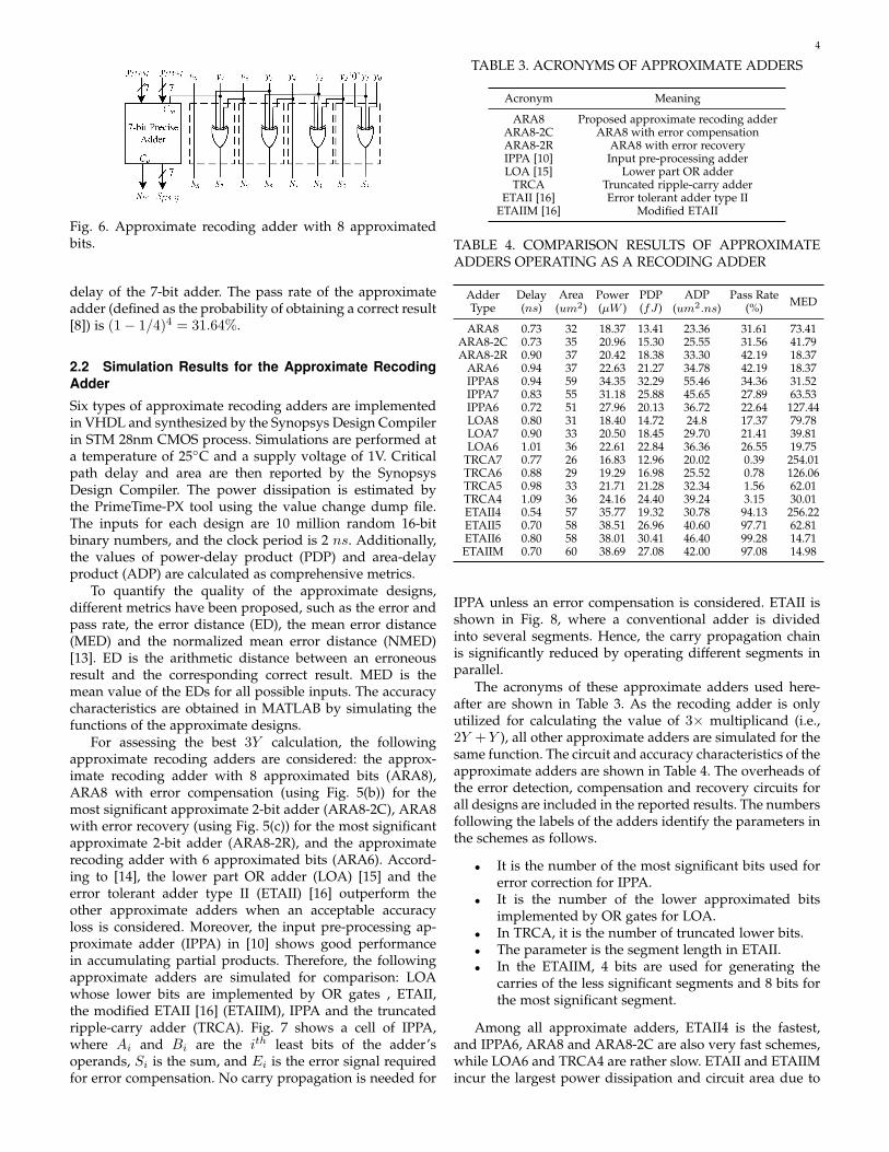
tiplier’s most significant part. However, the approximateadder can be used to implement the less significant partof the recoding adder and the most significant part can beimplemented by a precise adder. Fig. 6 shows the circuitof the approximate recoding adder with 8 approximatedbits; 4 approximate 2-bit adders and a 7-bit precise adderare utilized in the lower and higher parts, respectively. Forthe 16th bit (S16), S16 = y15 ⊕ y15 ⊕ Co = Co, where Co
is the carry-out of the 7-bit precise adder. In total, fourXOR gates and a 7-bit adder are used in the approximatedesign; this is simpler than the circuit of a ripple-carryadder; moreover, the critical path delay is given only by the
(a)
(b)
(c)
Fig. 5. (a) Error detection, (b) Partial error compensationand (c) Full error recovery circuits for the approximate 2-bit adder.
4
Fig. 6. Approximate recoding adder with 8 approximatedbits.
delay of the 7-bit adder. The pass rate of the approximateadder (defined as the probability of obtaining a correct result[8]) is (1− 1/4)4 = 31.64%.
2.2 Simulation Results for the Approximate RecodingAdder
Six types of approximate recoding adders are implementedin VHDL and synthesized by the Synopsys Design Compilerin STM 28nm CMOS process. Simulations are performed ata temperature of 25◦C and a supply voltage of 1V. Criticalpath delay and area are then reported by the SynopsysDesign Compiler. The power dissipation is estimated bythe PrimeTime-PX tool using the value change dump file.The inputs for each design are 10 million random 16-bitbinary numbers, and the clock period is 2 ns. Additionally,the values of power-delay product (PDP) and area-delayproduct (ADP) are calculated as comprehensive metrics.
To quantify the quality of the approximate designs,different metrics have been proposed, such as the error andpass rate, the error distance (ED), the mean error distance(MED) and the normalized mean error distance (NMED)[13]. ED is the arithmetic distance between an erroneousresult and the corresponding correct result. MED is themean value of the EDs for all possible inputs. The accuracycharacteristics are obtained in MATLAB by simulating thefunctions of the approximate designs.
For assessing the best 3Y calculation, the followingapproximate recoding adders are considered: the approx-imate recoding adder with 8 approximated bits (ARA8),ARA8 with error compensation (using Fig. 5(b)) for themost significant approximate 2-bit adder (ARA8-2C), ARA8with error recovery (using Fig. 5(c)) for the most significantapproximate 2-bit adder (ARA8-2R), and the approximaterecoding adder with 6 approximated bits (ARA6). Accord-ing to [14], the lower part OR adder (LOA) [15] and theerror tolerant adder type II (ETAII) [16] outperform theother approximate adders when an acceptable accuracyloss is considered. Moreover, the input pre-processing ap-proximate adder (IPPA) in [10] shows good performancein accumulating partial products. Therefore, the followingapproximate adders are simulated for comparison: LOAwhose lower bits are implemented by OR gates , ETAII,the modified ETAII [16] (ETAIIM), IPPA and the truncatedripple-carry adder (TRCA). Fig. 7 shows a cell of IPPA,where Ai and Bi are the ith least bits of the adder’soperands, Si is the sum, and Ei is the error signal requiredfor error compensation. No carry propagation is needed for
TABLE 3. ACRONYMS OF APPROXIMATE ADDERS
Acronym Meaning
ARA8 Proposed approximate recoding adderARA8-2C ARA8 with error compensationARA8-2R ARA8 with error recoveryIPPA [10] Input pre-processing adderLOA [15] Lower part OR adder
TRCA Truncated ripple-carry adderETAII [16] Error tolerant adder type II
ETAIIM [16] Modified ETAII
TABLE 4. COMPARISON RESULTS OF APPROXIMATEADDERS OPERATING AS A RECODING ADDER
AdderType
Delay(ns)
Area(um2)
Power(µW )
PDP(fJ)
ADP(um2.ns)
Pass Rate(%) MED
ARA8 0.73 32 18.37 13.41 23.36 31.61 73.41ARA8-2C 0.73 35 20.96 15.30 25.55 31.56 41.79ARA8-2R 0.90 37 20.42 18.38 33.30 42.19 18.37
ARA6 0.94 37 22.63 21.27 34.78 42.19 18.37IPPA8 0.94 59 34.35 32.29 55.46 34.36 31.52IPPA7 0.83 55 31.18 25.88 45.65 27.89 63.53IPPA6 0.72 51 27.96 20.13 36.72 22.64 127.44LOA8 0.80 31 18.40 14.72 24.8 17.37 79.78LOA7 0.90 33 20.50 18.45 29.70 21.41 39.81LOA6 1.01 36 22.61 22.84 36.36 26.55 19.75
TRCA7 0.77 26 16.83 12.96 20.02 0.39 254.01TRCA6 0.88 29 19.29 16.98 25.52 0.78 126.06TRCA5 0.98 33 21.71 21.28 32.34 1.56 62.01TRCA4 1.09 36 24.16 24.40 39.24 3.15 30.01ETAII4 0.54 57 35.77 19.32 30.78 94.13 256.22ETAII5 0.70 58 38.51 26.96 40.60 97.71 62.81ETAII6 0.80 58 38.01 30.41 46.40 99.28 14.71ETAIIM 0.70 60 38.69 27.08 42.00 97.08 14.98
IPPA unless an error compensation is considered. ETAII isshown in Fig. 8, where a conventional adder is dividedinto several segments. Hence, the carry propagation chainis significantly reduced by operating different segments inparallel.
The acronyms of these approximate adders used here-after are shown in Table 3. As the recoding adder is onlyutilized for calculating the value of 3× multiplicand (i.e.,2Y +Y ), all other approximate adders are simulated for thesame function. The circuit and accuracy characteristics of theapproximate adders are shown in Table 4. The overheads ofthe error detection, compensation and recovery circuits forall designs are included in the reported results. The numbersfollowing the labels of the adders identify the parameters inthe schemes as follows.
• It is the number of the most significant bits used forerror correction for IPPA.
• It is the number of the lower approximated bitsimplemented by OR gates for LOA.
• In TRCA, it is the number of truncated lower bits.• The parameter is the segment length in ETAII.• In the ETAIIM, 4 bits are used for generating the
carries of the less significant segments and 8 bits forthe most significant segment.
Among all approximate adders, ETAII4 is the fastest,and IPPA6, ARA8 and ARA8-2C are also very fast schemes,while LOA6 and TRCA4 are rather slow. ETAII and ETAIIMincur the largest power dissipation and circuit area due to
5
Fig. 7. The circuit of the input pre-processing adder cell [10].
Fig. 8. The diagram of the error tolerant type II adder [14].
the segmented structure, while TRCA is the most power andarea efficient design due to truncation. For the same reasons,ETAII and ETAIIM show a high pass rate (more than 90%),while TRCA has the lowest pass rate (less than 2%). Thehigh pass rates of ETAII4 and ETAII5 cannot guarantee ahigh MED, because the EDs are rather significant, though er-rors seldom occur. Although IPPA performs well in [10] forpartial product accumulation, it is not suitable for operatingas a recoding adder. This occurs because IPPA is designedfor an iterative addition in the accumulation of partialproducts for a multiplier. In this operation, error signalscan be accumulated efficiently (e.g., by using OR gates),and then the error is compensated at the final stage usingan accurate adder. For a recoding adder, however, the errormust be compensated immediately, which makes IPPA lessefficient. The power dissipation and area of the proposedapproximate adders and LOA are very close. However, theproposed approximate adders have higher pass rates andlower MEDs than LOA.
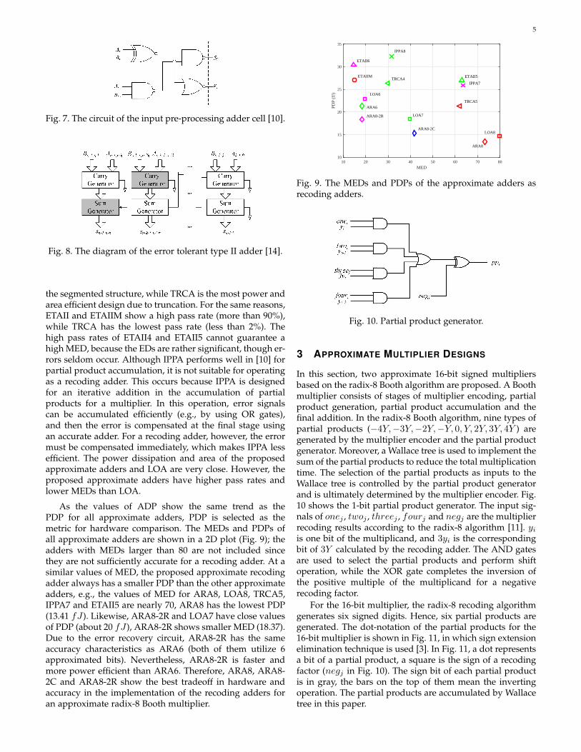
As the values of ADP show the same trend as thePDP for all approximate adders, PDP is selected as themetric for hardware comparison. The MEDs and PDPs ofall approximate adders are shown in a 2D plot (Fig. 9); theadders with MEDs larger than 80 are not included sincethey are not sufficiently accurate for a recoding adder. At asimilar values of MED, the proposed approximate recodingadder always has a smaller PDP than the other approximateadders, e.g., the values of MED for ARA8, LOA8, TRCA5,IPPA7 and ETAII5 are nearly 70, ARA8 has the lowest PDP(13.41 fJ ). Likewise, ARA8-2R and LOA7 have close valuesof PDP (about 20 fJ ), ARA8-2R shows smaller MED (18.37).Due to the error recovery circuit, ARA8-2R has the sameaccuracy characteristics as ARA6 (both of them utilize 6approximated bits). Nevertheless, ARA8-2R is faster andmore power efficient than ARA6. Therefore, ARA8, ARA8-2C and ARA8-2R show the best tradeoff in hardware andaccuracy in the implementation of the recoding adders foran approximate radix-8 Booth multiplier.
MED10 20 30 40 50 60 70 80
PDP
(fJ)
10
15
20
25
30
35
ARA8
ARA8-2C
ARA8-2R
ARA6
LOA8
LOA7
LOA6
TRCA5
TRCA4 ETAII5
ETAII6
ETAIIM
IPPA8
IPPA7
Fig. 9. The MEDs and PDPs of the approximate adders asrecoding adders.
Fig. 10. Partial product generator.
3 APPROXIMATE MULTIPLIER DESIGNS
In this section, two approximate 16-bit signed multipliersbased on the radix-8 Booth algorithm are proposed. A Boothmultiplier consists of stages of multiplier encoding, partialproduct generation, partial product accumulation and thefinal addition. In the radix-8 Booth algorithm, nine types ofpartial products (−4Y,−3Y,−2Y,−Y, 0, Y, 2Y, 3Y, 4Y ) aregenerated by the multiplier encoder and the partial productgenerator. Moreover, a Wallace tree is used to implement thesum of the partial products to reduce the total multiplicationtime. The selection of the partial products as inputs to theWallace tree is controlled by the partial product generatorand is ultimately determined by the multiplier encoder. Fig.10 shows the 1-bit partial product generator. The input sig-nals of onej , twoj , threej , fourj and negj are the multiplierrecoding results according to the radix-8 algorithm [11]. yiis one bit of the multiplicand, and 3yi is the correspondingbit of 3Y calculated by the recoding adder. The AND gatesare used to select the partial products and perform shiftoperation, while the XOR gate completes the inversion ofthe positive multiple of the multiplicand for a negativerecoding factor.
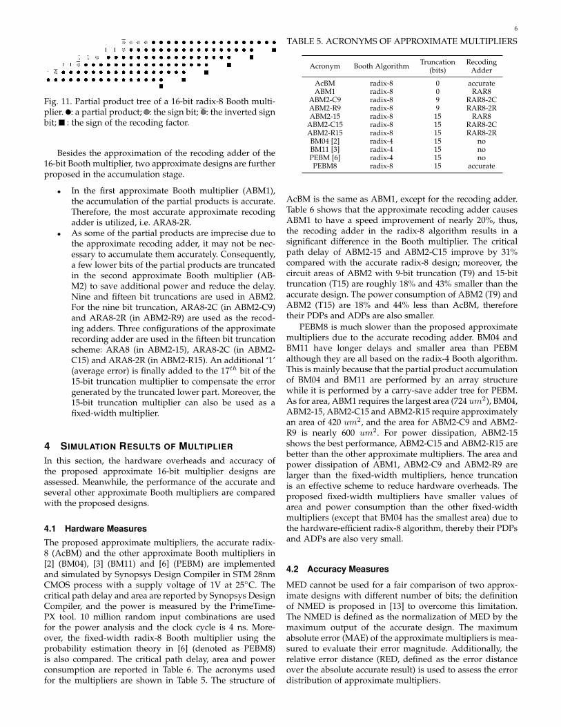
For the 16-bit multiplier, the radix-8 recoding algorithmgenerates six signed digits. Hence, six partial products aregenerated. The dot-notation of the partial products for the16-bit multiplier is shown in Fig. 11, in which sign extensionelimination technique is used [3]. In Fig. 11, a dot representsa bit of a partial product, a square is the sign of a recodingfactor (negj in Fig. 10). The sign bit of each partial productis in gray, the bars on the top of them mean the invertingoperation. The partial products are accumulated by Wallacetree in this paper.
6
Fig. 11. Partial product tree of a 16-bit radix-8 Booth multi-plier. : a partial product; : the sign bit; : the inverted signbit; : the sign of the recoding factor.
Besides the approximation of the recoding adder of the16-bit Booth multiplier, two approximate designs are furtherproposed in the accumulation stage.
• In the first approximate Booth multiplier (ABM1),the accumulation of the partial products is accurate.Therefore, the most accurate approximate recodingadder is utilized, i.e. ARA8-2R.
• As some of the partial products are imprecise due tothe approximate recoding adder, it may not be nec-essary to accumulate them accurately. Consequently,a few lower bits of the partial products are truncatedin the second approximate Booth multiplier (AB-M2) to save additional power and reduce the delay.Nine and fifteen bit truncations are used in ABM2.For the nine bit truncation, ARA8-2C (in ABM2-C9)and ARA8-2R (in ABM2-R9) are used as the recod-ing adders. Three configurations of the approximaterecording adder are used in the fifteen bit truncationscheme: ARA8 (in ABM2-15), ARA8-2C (in ABM2-C15) and ARA8-2R (in ABM2-R15). An additional ‘1’(average error) is finally added to the 17th bit of the15-bit truncation multiplier to compensate the errorgenerated by the truncated lower part. Moreover, the15-bit truncation multiplier can also be used as afixed-width multiplier.
4 SIMULATION RESULTS OF MULTIPLIER
In this section, the hardware overheads and accuracy ofthe proposed approximate 16-bit multiplier designs areassessed. Meanwhile, the performance of the accurate andseveral other approximate Booth multipliers are comparedwith the proposed designs.
4.1 Hardware Measures
The proposed approximate multipliers, the accurate radix-8 (AcBM) and the other approximate Booth multipliers in[2] (BM04), [3] (BM11) and [6] (PEBM) are implementedand simulated by Synopsys Design Compiler in STM 28nmCMOS process with a supply voltage of 1V at 25◦C. Thecritical path delay and area are reported by Synopsys DesignCompiler, and the power is measured by the PrimeTime-PX tool. 10 million random input combinations are usedfor the power analysis and the clock cycle is 4 ns. More-over, the fixed-width radix-8 Booth multiplier using theprobability estimation theory in [6] (denoted as PEBM8)is also compared. The critical path delay, area and powerconsumption are reported in Table 6. The acronyms usedfor the multipliers are shown in Table 5. The structure of
TABLE 5. ACRONYMS OF APPROXIMATE MULTIPLIERS
Acronym Booth Algorithm Truncation(bits)
RecodingAdder
AcBM radix-8 0 accurateABM1 radix-8 0 RAR8
ABM2-C9 radix-8 9 RAR8-2CABM2-R9 radix-8 9 RAR8-2RABM2-15 radix-8 15 RAR8
ABM2-C15 radix-8 15 RAR8-2CABM2-R15 radix-8 15 RAR8-2RBM04 [2] radix-4 15 noBM11 [3] radix-4 15 noPEBM [6] radix-4 15 noPEBM8 radix-8 15 accurate
AcBM is the same as ABM1, except for the recoding adder.Table 6 shows that the approximate recoding adder causesABM1 to have a speed improvement of nearly 20%, thus,the recoding adder in the radix-8 algorithm results in asignificant difference in the Booth multiplier. The criticalpath delay of ABM2-15 and ABM2-C15 improve by 31%compared with the accurate radix-8 design; moreover, thecircuit areas of ABM2 with 9-bit truncation (T9) and 15-bittruncation (T15) are roughly 18% and 43% smaller than theaccurate design. The power consumption of ABM2 (T9) andABM2 (T15) are 18% and 44% less than AcBM, thereforetheir PDPs and ADPs are also smaller.
PEBM8 is much slower than the proposed approximatemultipliers due to the accurate recoding adder. BM04 andBM11 have longer delays and smaller area than PEBMalthough they are all based on the radix-4 Booth algorithm.This is mainly because that the partial product accumulationof BM04 and BM11 are performed by an array structurewhile it is performed by a carry-save adder tree for PEBM.As for area, ABM1 requires the largest area (724 um2), BM04,ABM2-15, ABM2-C15 and ABM2-R15 require approximatelyan area of 420 um2, and the area for ABM2-C9 and ABM2-R9 is nearly 600 um2. For power dissipation, ABM2-15shows the best performance, ABM2-C15 and ABM2-R15 arebetter than the other approximate multipliers. The area andpower dissipation of ABM1, ABM2-C9 and ABM2-R9 arelarger than the fixed-width multipliers, hence truncationis an effective scheme to reduce hardware overheads. Theproposed fixed-width multipliers have smaller values ofarea and power consumption than the other fixed-widthmultipliers (except that BM04 has the smallest area) due tothe hardware-efficient radix-8 algorithm, thereby their PDPsand ADPs are also very small.
4.2 Accuracy Measures
MED cannot be used for a fair comparison of two approx-imate designs with different number of bits; the definitionof NMED is proposed in [13] to overcome this limitation.The NMED is defined as the normalization of MED by themaximum output of the accurate design. The maximumabsolute error (MAE) of the approximate multipliers is mea-sured to evaluate their error magnitude. Additionally, therelative error distance (RED, defined as the error distanceover the absolute accurate result) is used to assess the errordistribution of approximate multipliers.
7
TABLE 6. HARDWARE COMPARISON RESULTS OF THEAPPROXIMATE BOOTH MULTIPLIERS
MultiplierType
Delay(ns)
Area(um2)
Power(uW )
PDP(fJ)
ADP(um2.ns)
AcBM 2.99 737 371.9 1111.98 2203.63ABM1 2.38 724 363.3 865.84 1723.12
ABM2-C9 2.23 604 305.2 680.60 1346.92ABM2-R9 2.41 606 305.5 736.26 1460.46ABM2-15 2.07 419 206.8 428.08 867.33
ABM2-C15 2.07 422 208.1 430.77 873.54ABM2-R15 2.25 424 208.0 468.00 954.00
BM04 1.93 407 226.5 437.15 785.51BM11 1.96 475 258.1 505.88 931.00PEBM 1.83 528 264.3 483.67 966.24PEBM8 2.86 452 221.6 633.78 1292.72
The functions of the proposed and previous approximatemultipliers are simulated in MATLAB, their values of passrate, NMED, MAE and PRED (the probability of gettinga RED smaller than 2%) are reported in Table 7. ABM1gives the highest pass rate (55.937%), while the pass ratesof the other approximate multipliers are nearly 0 due totruncation. In terms of NMED, ABM1 has the smallest value,while ABM2-15 has the largest value. ABM1 and ABM2-R9 have similar NMEDs; i.e., the error due to the recodingadder is more significant than the one due to the truncation.The NMEDs of all proposed approximate multipliers usingARA8-2R as recoding adders (ABM1, ABM2-R9 and ABM2-R15) are smaller than PEBM8 and BM04. The proposedapproximate designs have relatively high MAEs because 3Yis required in the most significant partial product and hence,the error due to the approximate recoding adder incursin a rather large magnitude for the final multiplicationresult. However, as per their small values of NMED andhigh values of PRED , the probability of occurrence of alarge MAE is extremely small in these schemes. In termsof PRED , ABM1 incurs the largest value, and ABM2-C9 andABM2-R9 also have higher values of PRED than fixed-widthmultipliers. The accuracy of PEBM is higher than that ofPEBM8 in terms of NMED and PRED ; this indicates thatthe probability estimator based error compensation is moresuited for the radix-4 Booth algorithm than for the radix-8.In summary, ABM1 shows the best performance in terms ofpass rate, NMED and PRED , while ABM2-15 has the highestNMED and MAE.
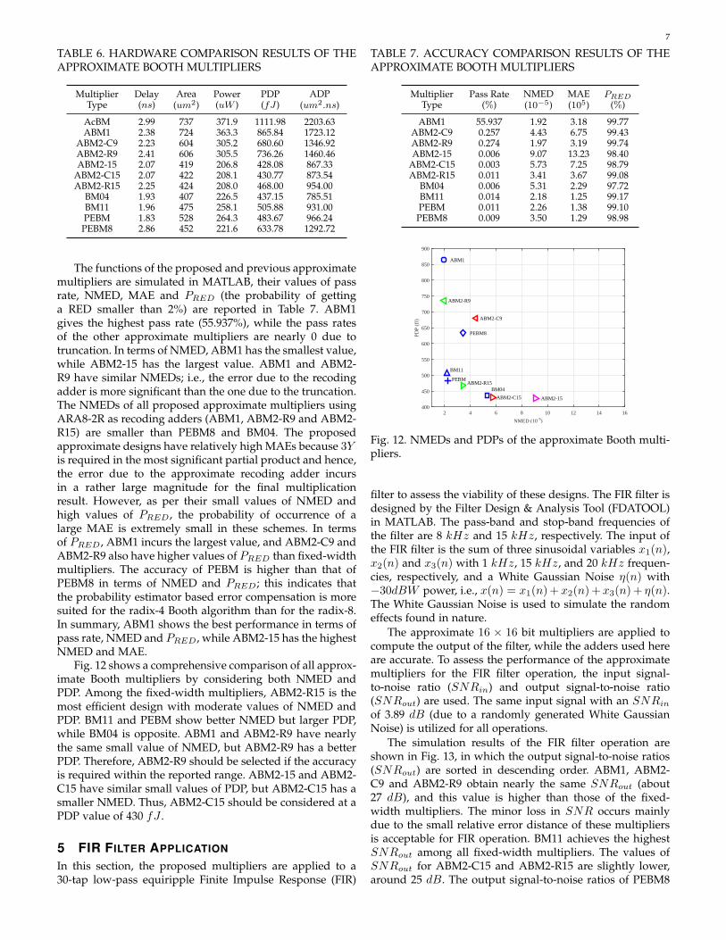
Fig. 12 shows a comprehensive comparison of all approx-imate Booth multipliers by considering both NMED andPDP. Among the fixed-width multipliers, ABM2-R15 is themost efficient design with moderate values of NMED andPDP. BM11 and PEBM show better NMED but larger PDP,while BM04 is opposite. ABM1 and ABM2-R9 have nearlythe same small value of NMED, but ABM2-R9 has a betterPDP. Therefore, ABM2-R9 should be selected if the accuracyis required within the reported range. ABM2-15 and ABM2-C15 have similar small values of PDP, but ABM2-C15 has asmaller NMED. Thus, ABM2-C15 should be considered at aPDP value of 430 fJ .
5 FIR FILTER APPLICATION
In this section, the proposed multipliers are applied to a30-tap low-pass equiripple Finite Impulse Response (FIR)
TABLE 7. ACCURACY COMPARISON RESULTS OF THEAPPROXIMATE BOOTH MULTIPLIERS
MultiplierType
Pass Rate(%)
NMED(10−5)
MAE(105)
PRED
(%)
ABM1 55.937 1.92 3.18 99.77ABM2-C9 0.257 4.43 6.75 99.43ABM2-R9 0.274 1.97 3.19 99.74ABM2-15 0.006 9.07 13.23 98.40
ABM2-C15 0.003 5.73 7.25 98.79ABM2-R15 0.011 3.41 3.67 99.08
BM04 0.006 5.31 2.29 97.72BM11 0.014 2.18 1.25 99.17PEBM 0.011 2.26 1.38 99.10PEBM8 0.009 3.50 1.29 98.98
NMED (10-5)
2 4 6 8 10 12 14 16PD
P (f
J)
400
450
500
550
600
650
700
750
800
850
900
PEBM8
BM04
BM11
ABM1
ABM2-C9
ABM2-R9
ABM2-15ABM2-C15
ABM2-R15 PEBM
Fig. 12. NMEDs and PDPs of the approximate Booth multi-pliers.
filter to assess the viability of these designs. The FIR filter isdesigned by the Filter Design & Analysis Tool (FDATOOL)in MATLAB. The pass-band and stop-band frequencies ofthe filter are 8 kHz and 15 kHz, respectively. The input ofthe FIR filter is the sum of three sinusoidal variables x1(n),x2(n) and x3(n) with 1 kHz, 15 kHz, and 20 kHz frequen-cies, respectively, and a White Gaussian Noise η(n) with−30dBW power, i.e., x(n) = x1(n)+ x2(n)+ x3(n)+ η(n).The White Gaussian Noise is used to simulate the randomeffects found in nature.
The approximate 16 × 16 bit multipliers are applied tocompute the output of the filter, while the adders used hereare accurate. To assess the performance of the approximatemultipliers for the FIR filter operation, the input signal-to-noise ratio (SNRin) and output signal-to-noise ratio(SNRout) are used. The same input signal with an SNRin
of 3.89 dB (due to a randomly generated White GaussianNoise) is utilized for all operations.
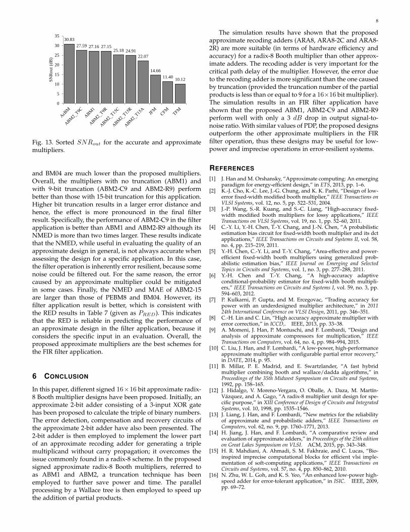
The simulation results of the FIR filter operation areshown in Fig. 13, in which the output signal-to-noise ratios(SNRout) are sorted in descending order. ABM1, ABM2-C9 and ABM2-R9 obtain nearly the same SNRout (about27 dB), and this value is higher than those of the fixed-width multipliers. The minor loss in SNR occurs mainlydue to the small relative error distance of these multipliersis acceptable for FIR operation. BM11 achieves the highestSNRout among all fixed-width multipliers. The values ofSNRout for ABM2-C15 and ABM2-R15 are slightly lower,around 25 dB. The output signal-to-noise ratios of PEBM8
8
30.8327.59 27.16 27.15
25.18 24.9122.07
14.6611.40 10.12
0
5
10
15
20
25
30
35
SNR
out (
dB)
Fig. 13. Sorted SNRout for the accurate and approximatemultipliers.
and BM04 are much lower than the proposed multipliers.Overall, the multipliers with no truncation (ABM1) andwith 9-bit truncation (ABM2-C9 and ABM2-R9) performbetter than those with 15-bit truncation for this application.Higher bit truncation results in a larger error distance andhence, the effect is more pronounced in the final filterresult. Specifically, the performance of ABM2-C9 in the filterapplication is better than ABM1 and ABM2-R9 although itsNMED is more than two times larger. These results indicatethat the NMED, while useful in evaluating the quality of anapproximate design in general, is not always accurate whenassessing the design for a specific application. In this case,the filter operation is inherently error resilient, because somenoise could be filtered out. For the same reason, the errorcaused by an approximate multiplier could be mitigatedin some cases. Finally, the NMED and MAE of ABM2-15are larger than those of PEBM8 and BM04. However, itsfilter application result is better, which is consistent withthe RED results in Table 7 (given as PRED). This indicatesthat the RED is reliable in predicting the performance ofan approximate design in the filter application, because itconsiders the specific input in an evaluation. Overall, theproposed approximate multipliers are the best schemes forthe FIR filter application.
6 CONCLUSION
In this paper, different signed 16×16 bit approximate radix-8 Booth multiplier designs have been proposed. Initially, anapproximate 2-bit adder consisting of a 3-input XOR gatehas been proposed to calculate the triple of binary numbers.The error detection, compensation and recovery circuits ofthe approximate 2-bit adder have also been presented. The2-bit adder is then employed to implement the lower partof an approximate recoding adder for generating a triplemultiplicand without carry propagation; it overcomes theissue commonly found in a radix-8 scheme. In the proposedsigned approximate radix-8 Booth multipliers, referred toas ABM1 and ABM2, a truncation technique has beenemployed to further save power and time. The parallelprocessing by a Wallace tree is then employed to speed upthe addition of partial products.
The simulation results have shown that the proposedapproximate recoding adders (ARA8, ARA8-2C and ARA8-2R) are more suitable (in terms of hardware efficiency andaccuracy) for a radix-8 Booth multiplier than other approx-imate adders. The recoding adder is very important for thecritical path delay of the multiplier. However, the error dueto the recoding adder is more significant than the one causedby truncation (provided the truncation number of the partialproducts is less than or equal to 9 for a 16×16 bit multiplier).The simulation results in an FIR filter application haveshown that the proposed ABM1, ABM2-C9 and ABM2-R9perform well with only a 3 dB drop in output signal-to-noise ratio. With similar values of PDP, the proposed designsoutperform the other approximate multipliers in the FIRfilter operation, thus these designs may be useful for low-power and imprecise operations in error-resilient systems.
REFERENCES
[1] J. Han and M. Orshansky, “Approximate computing: An emergingparadigm for energy-efficient design,” in ETS, 2013, pp. 1–6.
[2] K.-J. Cho, K.-C. Lee, J.-G. Chung, and K. K. Parhi, “Design of low-error fixed-width modified booth multiplier,” IEEE Transactions onVLSI Systems, vol. 12, no. 5, pp. 522–531, 2004.
[3] J.-P. Wang, S.-R. Kuang, and S.-C. Liang, “High-accuracy fixed-width modified booth multipliers for lossy applications,” IEEETransactions on VLSI Systems, vol. 19, no. 1, pp. 52–60, 2011.
[4] C.-Y. Li, Y.-H. Chen, T.-Y. Chang, and J.-N. Chen, “A probabilisticestimation bias circuit for fixed-width booth multiplier and its dctapplications,” IEEE Transactions on Circuits and Systems II, vol. 58,no. 4, pp. 215–219, 2011.
[5] Y.-H. Chen, C.-Y. Li, and T.-Y. Chang, “Area-effective and power-efficient fixed-width booth multipliers using generalized prob-abilistic estimation bias,” IEEE Journal on Emerging and SelectedTopics in Circuits and Systems, vol. 1, no. 3, pp. 277–288, 2011.
[6] Y.-H. Chen and T.-Y. Chang, “A high-accuracy adaptiveconditional-probability estimator for fixed-width booth multipli-ers,” IEEE Transactions on Circuits and Systems I, vol. 59, no. 3, pp.594–603, 2012.
[7] P. Kulkarni, P. Gupta, and M. Ercegovac, “Trading accuracy forpower with an underdesigned multiplier architecture,” in 201124th International Conference on VLSI Design, 2011, pp. 346–351.
[8] C.-H. Lin and C. Lin, “High accuracy approximate multiplier witherror correction,” in ICCD,. IEEE, 2013, pp. 33–38.
[9] A. Momeni, J. Han, P. Montuschi, and F. Lombardi, “Design andanalysis of approximate compressors for multiplication,” IEEETransactions on Computers, vol. 64, no. 4, pp. 984–994, 2015.
[10] C. Liu, J. Han, and F. Lombardi, “A low-power, high-performanceapproximate multiplier with configurable partial error recovery,”in DATE, 2014, p. 95.
[11] B. Millar, P. E. Madrid, and E. Swartzlander, “A fast hybridmultiplier combining booth and wallace/dadda algorithms,” inProceedings of the 35th Midwest Symposium on Circuits and Systems,1992, pp. 158–165.
[12] J. Hidalgo, V. Moreno-Vergara, O. Oballe, A. Daza, M. Martın-Vazquez, and A. Gago, “A radix-8 multiplier unit design for spe-cific purpose,” in XIII Conference of Design of Circuits and IntegratedSystems, vol. 10, 1998, pp. 1535–1546.
[13] J. Liang, J. Han, and F. Lombardi, “New metrics for the reliabilityof approximate and probabilistic adders,” IEEE Transactions onComputers, vol. 62, no. 9, pp. 1760–1771, 2013.
[14] H. Jiang, J. Han, and F. Lombardi, “A comparative review andevaluation of approximate adders,” in Proceedings of the 25th editionon Great Lakes Symposium on VLSI. ACM, 2015, pp. 343–348.
[15] H. R. Mahdiani, A. Ahmadi, S. M. Fakhraie, and C. Lucas, “Bio-inspired imprecise computational blocks for efficient vlsi imple-mentation of soft-computing applications,” IEEE Transactions onCircuits and Systems, vol. 57, no. 4, pp. 850–862, 2010.
[16] N. Zhu, W. L. Goh, and K. S. Yeo, “An enhanced low-power high-speed adder for error-tolerant application,” in ISIC. IEEE, 2009,pp. 69–72.