1 Appendix B Classifying Instruction Set Architecture Memory addressing mode Operations in the...
25
1 Appendix B • Classifying Instruction Set Architecture • Memory addressing mode • Operations in the instruction set • Control flow instructions • Instruction format CDA5155 Spring, 2007, Peir / University of Florida
-
Upload
cassandra-jones -
Category
Documents
-
view
222 -
download
1
Transcript of 1 Appendix B Classifying Instruction Set Architecture Memory addressing mode Operations in the...
1
Appendix B
• Classifying Instruction Set Architecture
• Memory addressing mode
• Operations in the instruction set
• Control flow instructions
• Instruction format
CDA5155 Spring, 2007, Peir / University of Florida

2
Classifying Architectures
• One important classification scheme is by the
type of addressing modes supported.– StackStack architecture: Operands implicitly on top of a stack.
(Early machines, Intel floating-point.)
– AccumulatorAccumulator architecture: One operand is implicitly an
accumulator (a special register). (Early machs.)
– General-purpose registerGeneral-purpose register architecture: Operands may be
any of a large (typically 10s-100s) # of registers.
• Register-memory architectures: One op may be memory.
• Load-store architectures: All ops are registers, except in
special load and store instructions.

3
Four Architecture Classes
Assembly for C:=A+B:
4
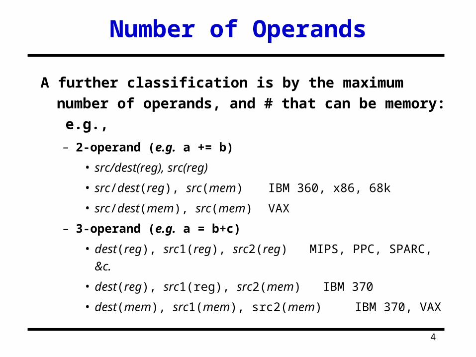
A further classification is by the maximum number of
operands, and # that can be memory: e.g.,
– 2-operand (e.g. a += b)
• src/dest(reg), src(reg)
• src/dest(reg), src(mem) IBM 360, x86, 68k
• src/dest(mem), src(mem) VAX
– 3-operand (e.g. a = b+c)
• dest(reg), src1(reg), src2(reg) MIPS, PPC, SPARC, &c.
• dest(reg), src1(reg), src2(mem) IBM 370
• dest(mem), src1(mem), src2(mem) IBM 370, VAX
Number of Operands
5
Endians & Alignment
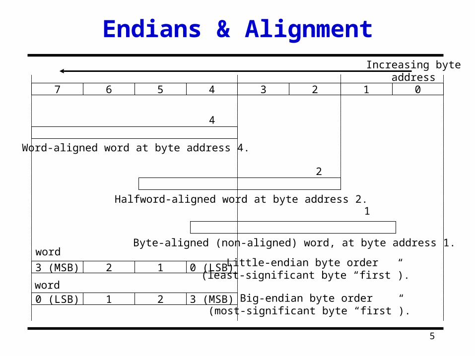
01234567
4
1
Word-aligned word at byte address 4.
Byte-aligned (non-aligned) word, at byte address 1.
2
Halfword-aligned word at byte address 2.
Increasing byteaddress
0 (LSB)123 (MSB)
3 (MSB)210 (LSB)
Little-endian byte order (least-significant byte “first”).
Big-endian byte order (most-significant byte “first”).
word
word
6
Addressing Modes
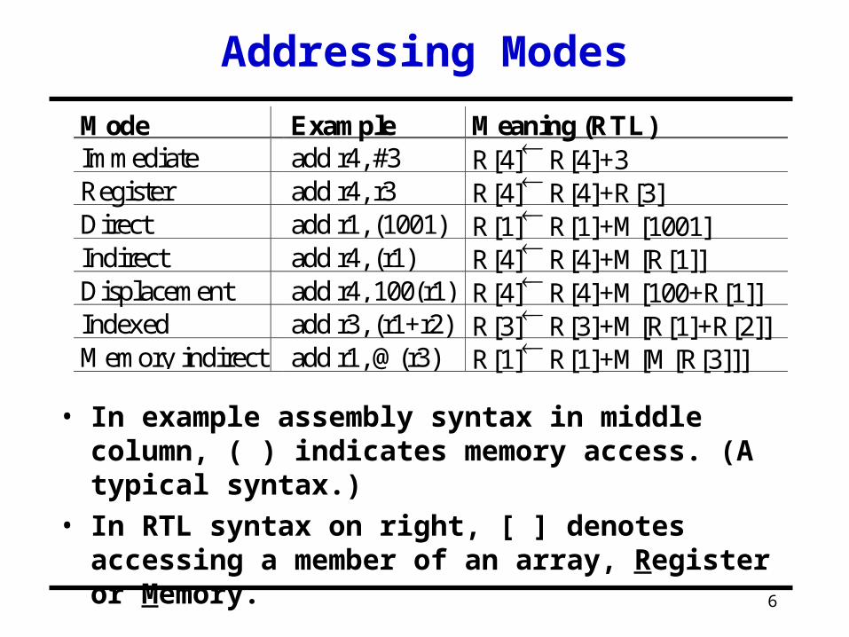
Mode Example Meaning (RTL)Immediate add r4, #3 R[4] R[4]+3Register add r4, r3 R[4] R[4]+R[3]Direct add r1, (1001) R[1] R[1]+M[1001]Indirect add r4, (r1) R[4] R[4]+M[R[1]]Displacement add r4, 100(r1) R[4] R[4]+M[100+R[1]]Indexed add r3, (r1+r2) R[3] R[3]+M[R[1]+R[2]]Memory indirect add r1, @(r3) R[1] R[1]+M[M[R[3]]]
• In example assembly syntax in middle column, ( ) indicates memory access. (A typical syntax.)
• In RTL syntax on right, [ ] denotes accessing a member of an array, Register or Memory.
7
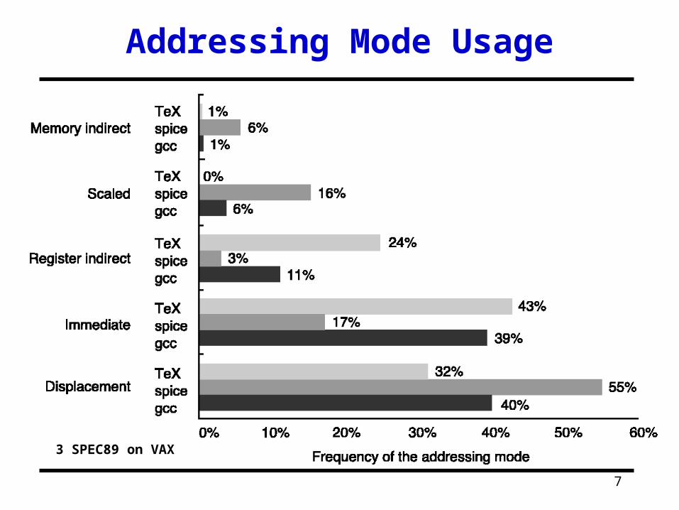
Addressing Mode Usage
3 SPEC89 on VAX
8
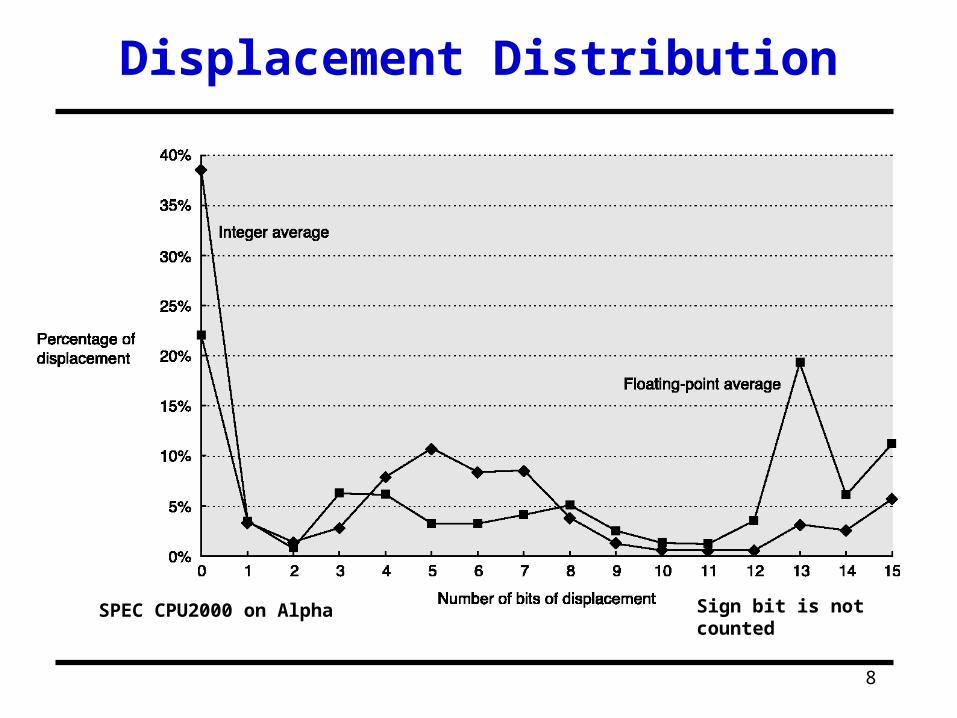
Displacement Distribution
SPEC CPU2000 on Alpha Sign bit is not counted
9
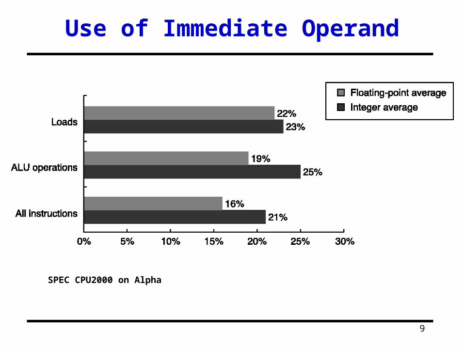
Use of Immediate Operand
SPEC CPU2000 on Alpha
10
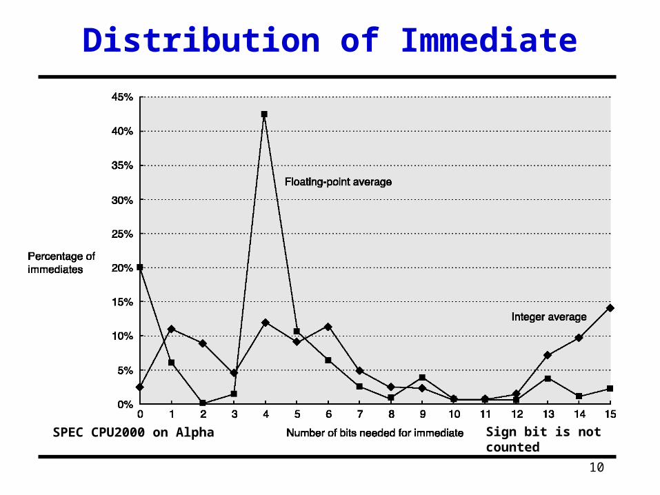
Distribution of Immediate
SPEC CPU2000 on Alpha Sign bit is not counted
11
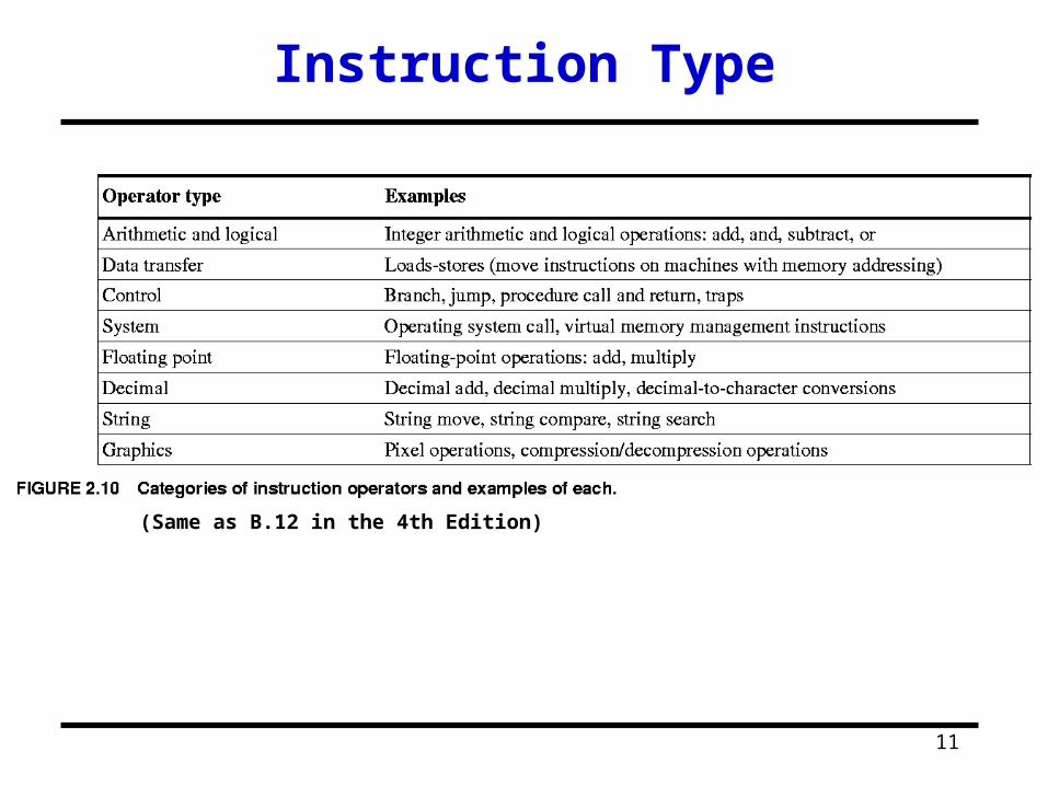
Instruction Type
(Same as B.12 in the 4th Edition)

12
Instruction Distribution
(Same as Fig. 2.16)(5 SPECint92)
13
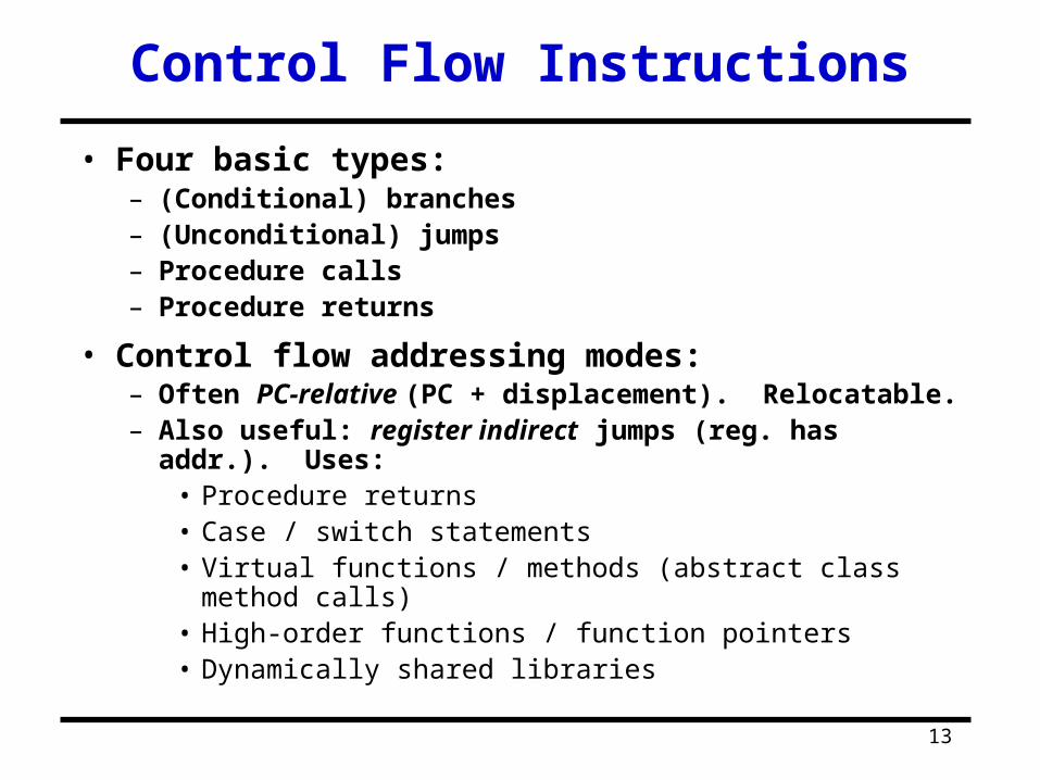
Control Flow Instructions
• Four basic types:– (Conditional) branches– (Unconditional) jumps– Procedure calls– Procedure returns
• Control flow addressing modes:– Often PC-relative (PC + displacement). Relocatable.– Also useful: register indirect jumps (reg. has addr.).
Uses:• Procedure returns• Case / switch statements• Virtual functions / methods (abstract class method calls)• High-order functions / function pointers• Dynamically shared libraries

14
Conditional Branch Options
• Condition Code (CC) Register– E.g.: X86, ARM, PPC, SPARC, …
– ALU ops set condition code flags in the CCR
– Branch just checks the flag
• Condition register– E.g.: Alpha, MIPS
– Comparison instruction puts result in a GPR
– Branch instruction checks the register
• Compare & Branch– E.g.: PA-RISC, VAX
– Compare & branch in 1 instruction.
15
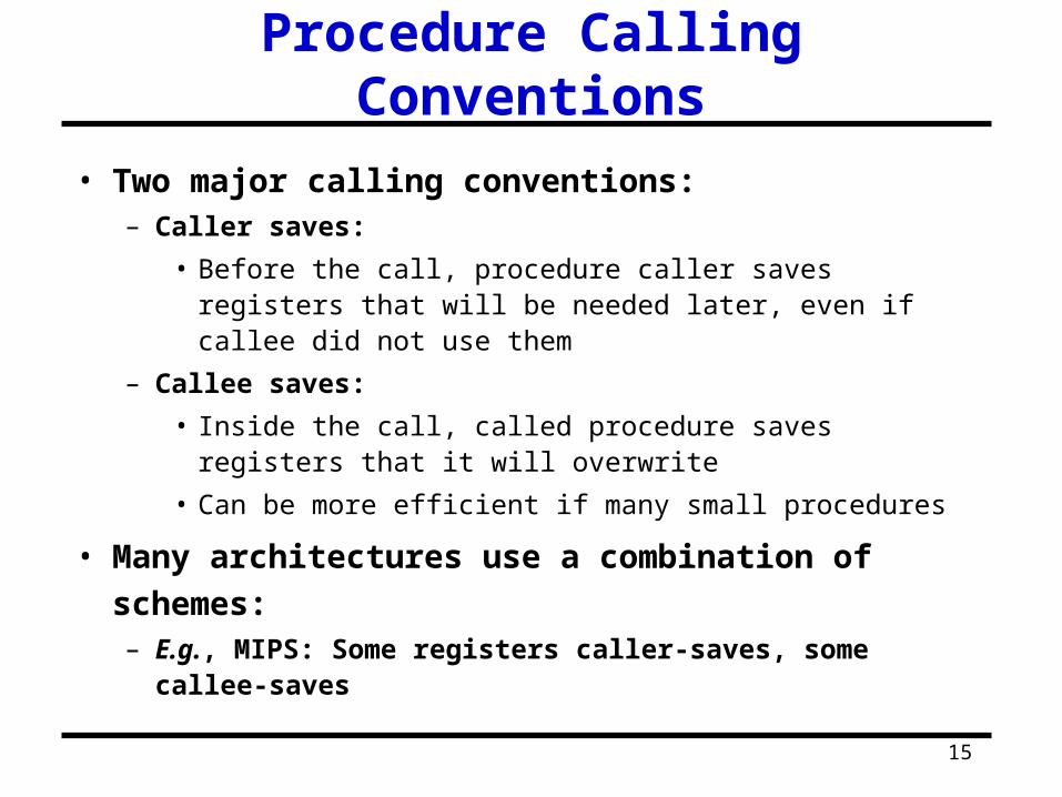
Procedure Calling Conventions
• Two major calling conventions:– Caller saves:
• Before the call, procedure caller saves registers that will be needed later, even if callee did not use them
– Callee saves:
• Inside the call, called procedure saves registers that it will overwrite
• Can be more efficient if many small procedures
• Many architectures use a combination of schemes:– E.g., MIPS: Some registers caller-saves, some callee-
saves
16
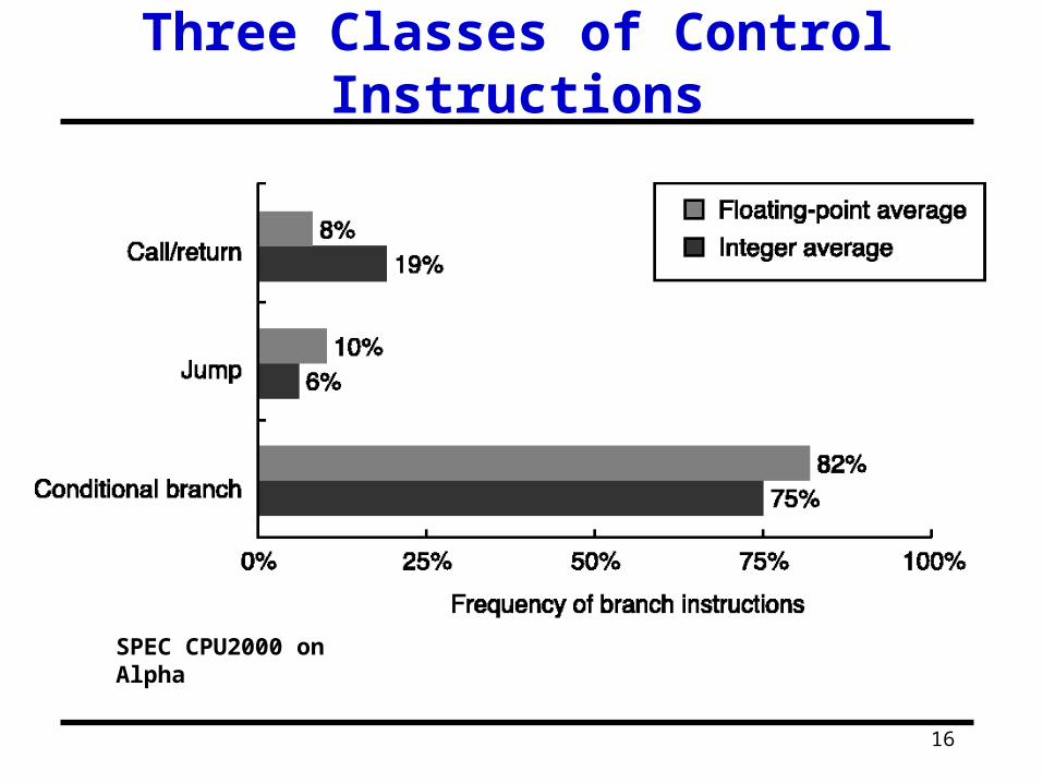
Three Classes of Control Instructions
SPEC CPU2000 on Alpha
17
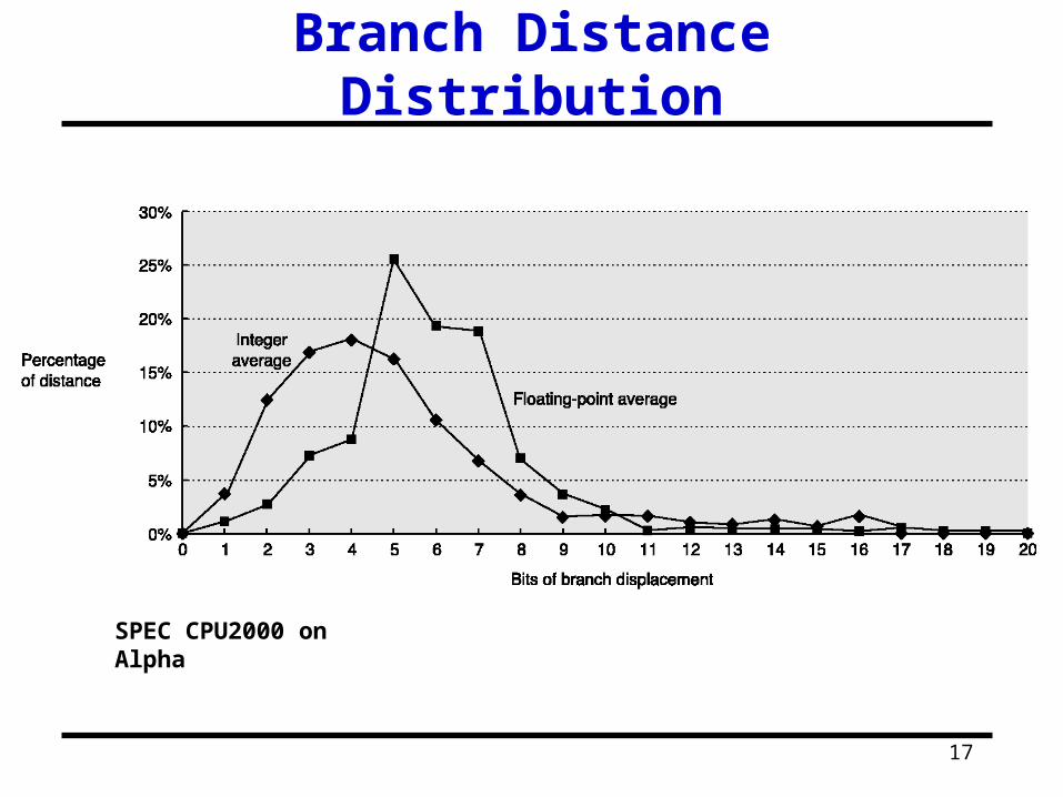
Branch Distance Distribution
SPEC CPU2000 on Alpha
18
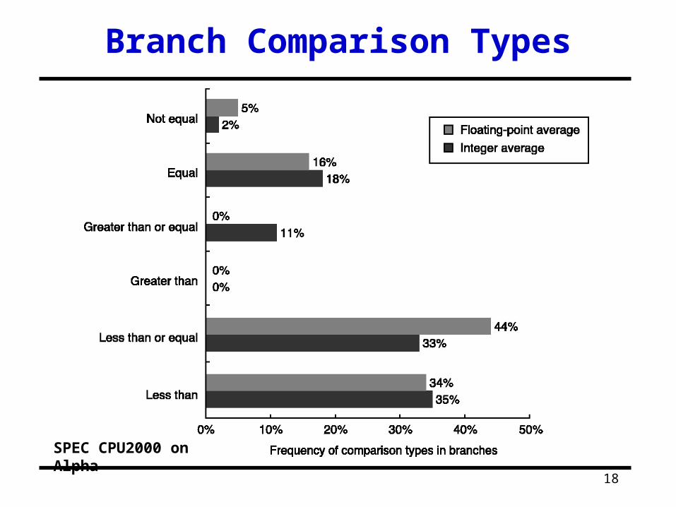
Branch Comparison Types
SPEC CPU2000 on Alpha

19
Encoding An Instruction Set
20
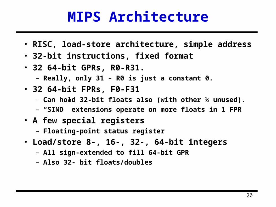
MIPS Architecture
• RISC, load-store architecture, simple address• 32-bit instructions, fixed format• 32 64-bit GPRs, R0-R31.
– Really, only 31 – R0 is just a constant 0.
• 32 64-bit FPRs, F0-F31– Can hold 32-bit floats also (with other ½ unused).– “SIMD” extensions operate on more floats in 1 FPR
• A few special registers– Floating-point status register
• Load/store 8-, 16-, 32-, 64-bit integers– All sign-extended to fill 64-bit GPR– Also 32- bit floats/doubles
21
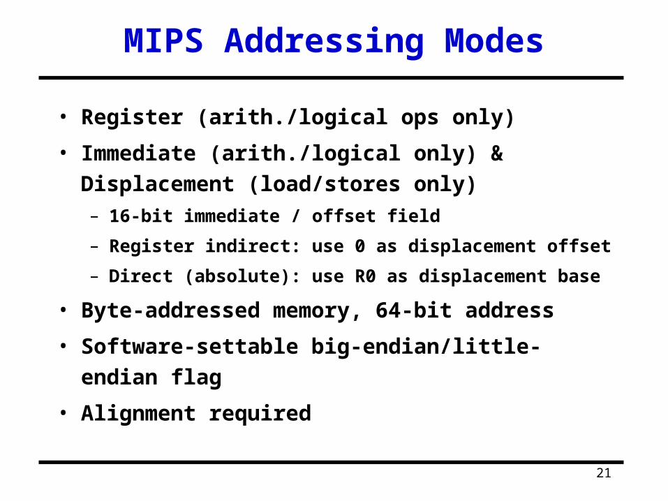
MIPS Addressing Modes
• Register (arith./logical ops only)
• Immediate (arith./logical only) & Displacement
(load/stores only)– 16-bit immediate / offset field
– Register indirect: use 0 as displacement offset
– Direct (absolute): use R0 as displacement base
• Byte-addressed memory, 64-bit address
• Software-settable big-endian/little-endian flag
• Alignment required

22
Inst. Format: I-type Instructions
23
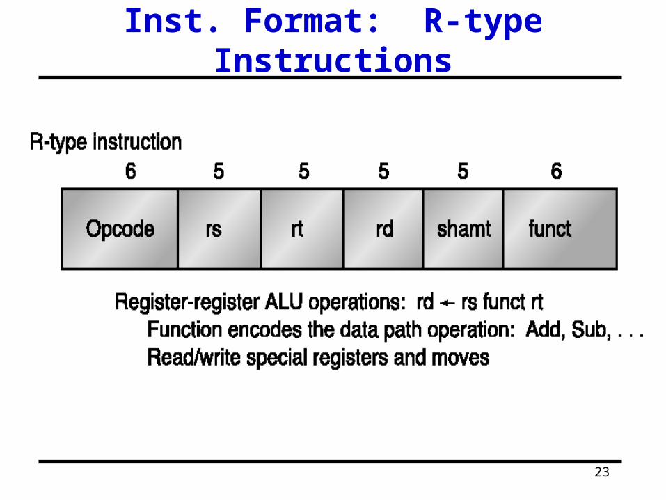
Inst. Format: R-type Instructions

24
Inst. Format: J-type Instructions

25
MIPS Instruction Set
• Go through Figures B.23-26 in textbook
• Branch and Jump Addresses– PC-relative addressing:
• Branch target address = (PC+4) + (Displacement || “00”); Note
instead of PC, (PC+4)(PC+4) for hardware convenience and the two
zeros is added due to wordword displacement.
– Jump (limited to 256MB range):
• (Upper 4 bits of Current PC) || (26-bits address in Jump) ||
(“00”)
– Long Jump:
• Jump register: save 32-bit target address in register