1 Aggressive Crunching of Extracted RC Netlists Vasant Rao, Jeff Soreff, Ravi Ledalla (IBM EDA,...
32
1 Aggressive Crunching of Extracted RC Netlists Vasant Rao, Jeff Soreff, Ravi Ledalla (IBM EDA, Fishkill, NY), Fred Yang (IBM EDA, Almaden, CA)
-
Upload
gabriel-sanders -
Category
Documents
-
view
218 -
download
2
Transcript of 1 Aggressive Crunching of Extracted RC Netlists Vasant Rao, Jeff Soreff, Ravi Ledalla (IBM EDA,...

1
Aggressive Crunching of Extracted RC Netlists
Vasant Rao, Jeff Soreff, Ravi Ledalla
(IBM EDA, Fishkill, NY),
Fred Yang (IBM EDA, Almaden, CA)
2
Agenda
• Motivation for RC Crunching
• Internal Node Elimination (TICER)
• Resistor Short/Update (TICER+)
• Examples
• Results

3
Motivation for RC Crunching
• Netlists generated by Circuit Extractors have far too many resistors which slow down Circuit Simulation significantly Size of the netlist is huge
• Large Circuit Matrices
Wide range of dynamic time-constants• due to wide range of resistor values
• causes time-step control problems

4
RC Crunching Goals• Crunch Extracted RC netlist down significantly
reduce size (number of nodes/resistors) preserve sparsity preserve total capacitance give user a size vs accuracy control knob
• size of crunched network should vary inversely with error user is willing to tolerate.
• If user does not care for accuracy, the crunched network should be a single node with no resistors.
Should have potential for Complete Crunching
5
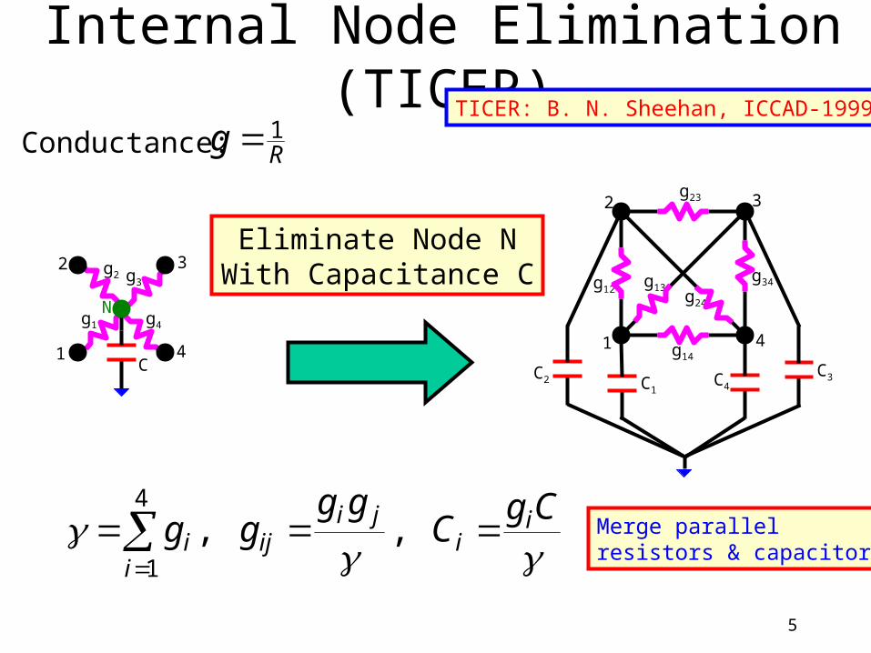
Internal Node Elimination (TICER)
Cg
Cgg
gg ii
jiij
ii
,,
4
1
Eliminate Node NWith Capacitance C
Conductance: Rg 1
C
g4
g3g2
g1
1
2 3
4
N
Merge parallelresistors & capacitors
C3
g12g13
g23
g14
g24
g34
1
2 3
4
C2 C4C1
TICER: B. N. Sheehan, ICCAD-1999

6
TICER Properties• Eliminates only internal (not source/sink) node.
Preserves Elmore Delay. Handles Coupling Capacitors
• TICER eliminates internal nodes with:
• After elimination of a node of degree k: Node count reduces by 1. Resistors increase by fill-in count =
• Restrict to preserve sparsity
C User Defined Threshold
EquilibriumTime Constant
kmkk 2
)1(
#New R’samong
neighbors
#Old R’samong
neighbors
#Deleted R’s

7
Resistor Short/Update (TICER+)
• TICER does not eliminate sources/sinks.
• Fill-in count restriction to preserve sparsity conflicts with complete crunching goal.
• TICER+ consists of: First run TICER with threshold and fill-in limit
• Recommend = 0.
Then short certain resistors and (possibly) update values of neighboring resistors
• Work with Elmore delay (satisfies additive relations)
• Limit accumulated delay error < /10.

8
• First consider RC-Tree:
RootI A B
K
J
R
RK
RJRI
Notation:
X
X
X
C
D
D~
Delay from Root to Node X before Shorting R
Delay from Root to Node X after Shorting R
Cumulative Down-stream Capacitance at X.
JJBJ
KKAK
BAB
AIIA
CRDD
CRDD
CRDD
CRDD
Additive Relations

9
• After shorting R between A and B:
RootI
AB
K
JRK+K
RJ+JRI+I
JJJABJ
KKKABK
ABIIIAB
CRDD
CRDD
CRDD
)(~~)(~~
)(~~

10
Optimal Solution:• Update ONLY neighbors RJ of R connected to B:
• This results in
• Note: Cannot preserve Elmore Delays at each sink Delay error occurs at the merged node only No error for sinks at A. Only error for sink at B. All perturbations are positive - good.
0,,0 KJ
BJI C
CR
B
XXAAB
CRError
BAXDDDD
,~,~
BAX
XXBABAAB DDDDDDError,
~~~Perturb resistors to minimize error due to shorting resistor R:
Optimization Problem
No UpdateNeeded ifB is a leaf
Coupling
Capacitors
Handled

11
Overall TICER+ Crunching Algorithm
1. Run TICER with user-defined anda. First only internal nodes with degree 1 or 2.
b. Then restrict to fill-in count of .
2. Find Minimum (Resistive) Spanning Tree
3. Pick leaf R with smallest
4. Short R and accumulate Error at merged node.
5. Check if total accumulated Error is
6. Repeat step 3 until above check fails.
BCR
BCR
10
No update needed since R is a leaf

12
Example1A
B
C
D
E
F
G
HI
S
1 source S9 sinks A-ISink Cap = 10fFInternal Pin Cap = 1fFAll R’s = 1User sets = 1psInitially delay error =0at all nodes.
RC-Tree after TICER with = 0
14 nodes13 resistors
00
0
0
0
0
0
0
0
0
0
0
0
Cannot Eliminateany Internal Node
10fF
1

13
A
B
C
D
E
F
G
HI
S
After 1 short
0
0
0
0
0
0
0
0
00
0
10fs

14
ABC
D
E
F
G
HI
S
After 3 shorts
0
0
0
0
0
0
00
0
10fs

15
ABC
DEF
GHI
S
After 9 shorts
0
10fs
10fs
10fs
31fF
1

16
ABC
DEF
GHI
S
After 10 shorts
41fs
10fs
10fs

17
ABCDEFGHIS
After 12 shorts
41fs
Final Network:2 nodes1 resistor
Cap = 94fF
Maximum delay error is 41fs < = 100fs.
Further shorting will result in a delay error = 41 + 1.0*94 = 135fs > = 100fs
1

18
Example2
8
18
9
19
25
3 2 1 4 6 11 16 15 14 13
24
52
41
3364
58
22
474648
38
3055
6137
29
54
60
21
44
43
35
27
45
5359
36 28
12
20
42
34
26
510 7 1723
5051
40
325763
49
56
62
39
31
User sets: = 8ps = 0
65 resistors
64 nodes
2 loops

19
8
18
9
19
25
3 2 1 4 6 11 16 15 14 13
24
52
41
3364
58
22
474648
38
3055
6137
29
54
60
21
44
43
35
27
45
5359
36 28
12
20
42
34
26
510 7 1723
5051
40
325763
49
56
62
39
31
20
8
18
19
25
3 2 1 4 6 11 16 15 14 13
24
52
41
3364
58
22
474648
38
3055
6137
29
54
60
21
44
43
35
27
45
5359
36 28
20
42
34
26
23
5051
40
325763
49
56
62
39
31
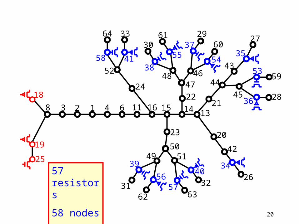
57 resistors
58 nodes
0 loops

21
8
18
19
25
3 2 1 4 6 11 16 15 14 13
24
52
41
3364
58
22
474648
38
3055
6137
29
54
60
21
44
43
35
27
45
5359
36 28
20
42
34
26
23
5051
40
325763
49
56
62
39
31

22
8
18
19
25
16 15 14 13
52
4158
474648
38
5537
54
44
35
45
53
36
34
5051
40
57
49
56
39
Done with internal nodes with 2 or less resistive neighbors.
Now work on internalnodes with 3 or moreresistive neighbors.
No loops!!!
30 resistors
31 nodes
0 loops

23
8
18
19
25
16 14 13
52
4158
474648
38
5537
54
44
35
45
53
36
34
5051
40
57
49
56
39
LoopFormed

24
18
19
25
1614
4158
464838
5537
54
44
35
53
36
34
50
40
5756
3930 resistors
23 nodes
Internal Node Elimination (TICER) phase completed. Further elimination will increase resistor count (cause fill-ins)

25
18
19
25
1614
4158
464838
5537
54
44
35
53
36
34
50
40
5756
3930 resistors
23 nodes
8 links
Begin Resistor Short/Update Phase: Find Minimum Resistor Spanning Tree and select Root
Root
0.66ps
/10 = 0.8ps

26
18
19
25
16
4158
464838
5537
54
44
35
53
36
34
50
40
5756
3928 resistors
22 nodes
7 links
Root
0.66ps
0.62ps
0.22ps
0.67ps
0.67ps0.67ps
0.22ps 0.22ps
0.22ps
0.22ps
0.22ps 0.73ps0.66ps
0.66ps

27
18
19
25
5554
53
34
11 resistors
9 nodes
3 links
Root
0.66ps
0.67ps
0.67ps
0.66ps0.66ps
57
58
0.73ps

28
18
19
25
5554
53
34
11 resistors
9 nodes
3 links
Root
0.66ps
0.67ps+0.13ps
0.67ps
0.66ps0.66ps+0.02ps
57
58
0.73ps

29
18
58
55
53
5 resistors
5 nodes
1 link
Root
0.8ps
0.68ps
0.67ps
0.73ps
57
Any further shorting will violate 0.8psdelay error bound
End of Shorting Phase: Final RC Network after Crunching- Note that resistor update formula not used.

30
Results• TICER+ implemented in Transistor-level Static Timing
Analyser (EinsTLT) used by IBM in production. EinsTLT uses a fast simulator (ACES)
• TICER+ performance measured by run-time savings in EinsTLT
• TICER+ accuracy measured by sink-to-sink stage-delay (d) difference (): computed by EinsTLT/ACES
• NOT Elmore Delay RC
d
)(max),(min originalcrunched
stagesoriginalcrunched
stagesdddd

31
Network Size vs Threshold
7500
3
2674
2
1849
1
1288
138
0
7399
6
2350
7
1698
0
4522
3509
3379
0
10000
20000
30000
40000
50000
60000
70000
80000
0 0.1ps 1.0ps 10.0ps 0.1ns 1.0ns
Threshold
#Resistors
#Nodes
EinsTLT Run Time vs Threshold
19.88
9.04
5.26
2.56 2.42 2.4
0
5
10
15
20
25
0 0.1ps 1.0ps 10.0ps 0.1ns 1.0ns
Threshold
CP
U H
ours Run Time
EinsTLT Accuracy Range vs Threshold
-0.44 -0.94 -2.14
-24.3-24.3
0.22 0.181.85 2.82
7.37
-30
-25
-20
-15
-10
-5
0
5
10
15
20
25
30
0 0.1ps 1.0ps 10.0ps 0.1ns 1.0ns
Thresholdpi
co-s
econ
ds
Accuracy Range
Threshold of TICER+ controls Run-Time vs Accuracy of EinsTLT 0 No Crunching1.0ns Complete Crunching
a
Recommended Thresholds

32
Network Size vs Threshold (TICER+)
7500
3
2674
2
1849
1
1288
138
0
7399
6
2350
7
1698
0
4522
3509
3379
0
10000
20000
30000
40000
50000
60000
70000
80000
0 0.1ps 1.0ps 10.0ps 0.1ns 1.0ns
Threshold
#Resistors
#Nodes
Network Size vs Threshold at Fill-in Number = 0 (TICER ONLY)
7500
3
2950
2
2949
3
2949
1
2949
1
2949
1
7399
6
2596
0
2595
1
2594
9
2594
9
2594
9
0
10000
20000
30000
40000
50000
60000
70000
80000
0 0.1ps 1.0ps 10.0ps 0.1ns 1.0ns
Threshold
#Resistors
#Nodes
Network Size vs Fill-in Numberat Threshold=1.0ns (TICER ONLY)
2949
1
3111
8 3760
3
4162
4
4524
7
6545
2
2594
9
2494
6
2313
8
2281
5
2235
3
2182
4
0
10000
20000
30000
40000
50000
60000
70000
80000
0 1 5 10 20 100
Fill-in Number
#Resistors
#Nodes
Just TICER by itself is not good enough:• Size saturates too soon at fixed fill-in number
• Increasing fill-in number: increases resistors significantly reduces nodes slightly