1 A Tree Based Router Search Engine Architecture With Single Port Memories Author: Baboescu,...
26
1 A Tree Based Router Search Engine Architecture With Single Port Memories Author: Baboescu , F. Tullsen , D.M. Rosu , G. Singh, S. Publisher: Computer Architecture, 2005. ISCA '05. Proceedings. 32 nd International Presenter: Po Ting Huang Date:2009/12/23
-
date post
19-Dec-2015 -
Category
Documents
-
view
218 -
download
0
Transcript of 1 A Tree Based Router Search Engine Architecture With Single Port Memories Author: Baboescu,...

1
A Tree Based Router Search Engine Architecture With Single
Port Memories
Author:Baboescu, F. Tullsen, D.M. Rosu, G. Singh, S.
Publisher:Computer Architecture, 2005. ISCA '05. Proceedings. 32nd International
Presenter:Po Ting Huang
Date:2009/12/23

2
Introduction
This paper describes the pipeline architecture which provides both high execution throughput and balanced memory distribution
dividing the tree into subtrees and allocating each subtree separately
allowing searches to begin at any pipeline stage The architecture is validated by implementing and si
mulating state of the art solutions for IPv4 lookup, VPN forwarding and packet classification.
Provide a solutions do well in terms of performance, efficiency, and cost

3
Background
Rapid growth in network link rates poses a strong demand on high speed packet forwarding engines
Searching engine’s work has been a significant bottleneck for core routers. using pipelining can significantly improve the throughput

4
memory allocation Problem
For trie-based searching, a simple approach is to map each trie level onto a private pipeline stage
this approach results in unbalanced trie node distribution over different pipeline stages
the stage storing a larger number of trie nodes needs more time to access the larger memory
When there is intensive route insertion, the larger stage can lead to memory overflow

5
Conventional solution
conventional approaches use either complex dynamic memory allocation schemes (dramatically increasing the hardware complexity) or over-provision each of the pipeline stages (resulting in memory waste)

6
First contribution
we introduce our first contribution: an additional degree of freedom for the search operation. We allow the search to start at any stage in the pipeline.
For every search, the starting position is picked using a hash function based on information in the packet header.
Ip lookup and packet classification

7
Sub tree Allocation

8
Sub tree Allocation
To keep the explanation simple, let us assume that the tree has four subtrees, called s1….s4
Furthermore, the depth of each subtree is four levels. We assume that this search structure is implemented
on a four stage pipeline. The stages of the pipeline are called p1….p4 The first level of the subtree S1 called s The first leve
l of the subtree s1 called s is stored and processed by the pipeline stage p1 The second level s , is stored and processed by the pipeline stage p2 and so on. Subtree s2 s3 s4 goes on
21
111

9
Sub tree Allocation con.
By doing so, the pipeline allocates nearly equal amounts of memory to each stage, by virtually allocating a “subtree” in each of the stages.

10
two simplifications
In practice, we relax these two simplifications in this illustration.
First:We allow more subtrees than pipeline stages (processing elements), thus implying multiple subtrees may have the same start node.
Second:We also allow the maximum depth of each subtree to be less than or equal to the number of pipeline stages.

11
Conflicts
However, introducing this new degree of freedom that allows search tasks to start execution from any pipeline stage impacts the throughput of the system.
This is because of potential conflicts between the new tasks and the ones that are in execution.

12
Second contribution
It modifies the regular pipeline structure and behavior as follows.
Each pipeline stage works at a frequency f=2*F where F is the maximum throughput of the input
All tasks traverse the pipeline twice and are inserted at the first pipeline stage,irrespective of their starting stage (for execution) in the pipeline.

13
Architecture of Ring Pipeline

14
Second contribution con.
Each pipeline stage accommodates two data paths (virtual data paths – they can share the same physical wires).
The first data path (represented by the top lines) is active during the odd clock cycles and it is used for a first traversal of the pipeline. During this traversal a task Ti traverses the pipeline until its starting stage I and continues the execution until the last stage of the pipeline

15
Second contribution con.
The second data path is traversed during even cycles and allows the task to continue its execution on the pipeline stages that are left. Once a task finishes executing, its results are propagated to the output through the final stage.
For example~~~~~~~~

16
Guarantees the following
1) an output rate equal to the input rate 2) all the tasks exit in order
3) all the tasks have a constant latency through the pipeline equal to N*1/F
4) while communication between processors occurs only between neighbors in a linear ordering of the processors (1) the need for a scheduler for both input and output of the task (2) the communication complexity.

17
Selecting the Subtrees
Ideally, the subtrees to be allocated should have relatively equal size (approximately the same number of nodes)
We provide an iterative algorithm that takes as input the original trie and at each step identifies one subtrie that contains a number of nodes which is the closest to a desired value (threshold).
The result of the algorithm is a list of tuples. Each tuple is made up of the root node of a subtrie together with the longest matching prefix of this node.

18
The Allocation of the Subtrees
Our heuristic considers one subtree at a time, randomly picked from the set of subtrees identified using the algorithm described in the previous method, and allocates it such that the level in the new subtree that requires the minimum amount of memory corresponds to the pipeline stage that already uses the largest amount of memory.
19
Evaluation
Focuses on the following two critical questions 1) What is the overall waste in the memory space du
e to our new model? 2) What is the maximum throughput and expected lat
ency our scheme can provide? we synthesized in Verilog the computational logic for
each pipeline stage for both Eatherton’s IP lookup algorithm and the HyperCuts algorithm using 0.13um technology

20
Search Latency and Throughput
When our balanced allocation algorithm is applied, we find that all searches analyzed in this research, except one, can be implemented with memory latency less than 2ns
The longest path delay in the computation of the next node address in both algorithms is smaller than 1ns
This combines with a 2ns memory access time to a allow a 3ns execution delay per pipeline stage
21
Search Latency and Throughput con.
Given the architecture of Section 2, a pipeline running at 330MHZ(3 ns per stage) achieves a search throughput of 6ns per packet
All the searches through the pipeline have a latency that is constant and is double the latency of a one way pipeline traversal. The overall latency of a search operation using the Eatherton algorithm [11] for the IPv4 lookup is 8*2*3ns=48ns assuming an eight-stage pipeline with

22
Memory Distribution per Pipeline Stage
Evaluation of IP Lookup
23
Evaluation of IP Lookup
an IP prefix table with about 500000 entriesrequires almost 11Mbits of memory for one stage Asaresult the memory access time increases to about 3.5ns
In comparison, our new pipeline scheme has a maximum of 2.9Mbits of memory allocated per stage As a result the memory access time is reduced to 1.4ns

24
Evaluation of IP Lookup con.
25
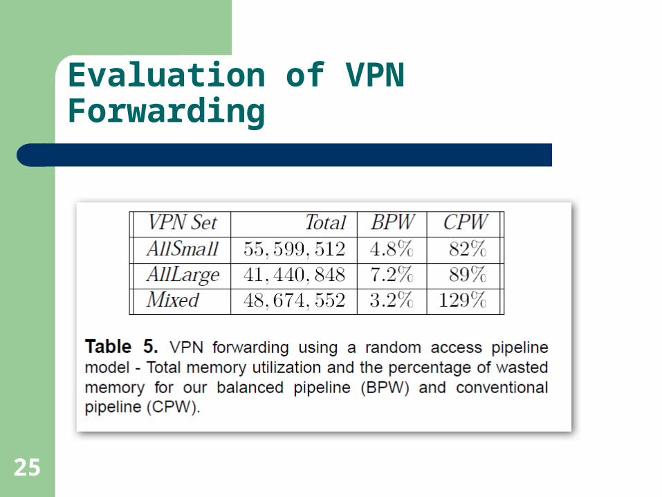
Evaluation of VPN Forwarding

26
Evaluation of the Packet Classification Algorithm(HyperCuts)


![Ancient history [by D.M. Masson]....Title Ancient history [by D.M. Masson]. Author David Mather Masson](https://static.fdocuments.in/doc/165x107/60ec6d4334ac5766a325c5a1/ancient-history-by-dm-masson-title-ancient-history-by-dm-masson-author.jpg)

![Arthur Conan Doyle - Un Studiu in Rosu [Ibuc.info]](https://static.fdocuments.in/doc/165x107/577cda881a28ab9e78a5ddb2/arthur-conan-doyle-un-studiu-in-rosu-ibucinfo.jpg)