1 A Taxonomy of Communication Networks Y. Richard Yang 1/16/2008.
61
1 A Taxonomy of Communication Networks Y. Richard Yang 1/16/2008
-
Upload
tamsin-allen -
Category
Documents
-
view
215 -
download
1
Transcript of 1 A Taxonomy of Communication Networks Y. Richard Yang 1/16/2008.
1
A Taxonomy of Communication Networks
Y. Richard Yang
1/16/2008
2
Outline
Recap A taxonomy of communication networks Summary

3
Recap A protocol defines the format and the order of
messages exchanged between two or more communicating entities, as well as the actions taken on the transmission or receipt of a message or other events.
Some implications of the past: ARPANET is sponsored by ARPA
The initial IMPs (routers) were made by a small company
Many networks
Commercialization
design should survive failures
internetworking: need a network to connect networks
keep the network simple
architecture supporting distributed, autonomous systems

4
Backbone ISPISP ISP
Recap: Current Internet Physical Infrastructure
Residential access Cable Fiber DSL Wireless
Campus access, e.g.,
Ethernet Wireless
The Internet is a network of networks
Each individually administrated network is called an Autonomous System (AS)

5
Northern CrossRoads (NoX) Aggregation Point (AP)
http://www.nox.org/NoXAPConfig3-01.jpg

6
Abilene I2 Backbone
http://weathermap.grnoc.iu.edu/abilene_jpg.html

7Qwest Backbone Map
http://www.qwest.com/largebusiness/enterprisesolutions/networkMaps/preloader.swf

8
ATT Global Backbone IP Network
From http://www.business.att.com
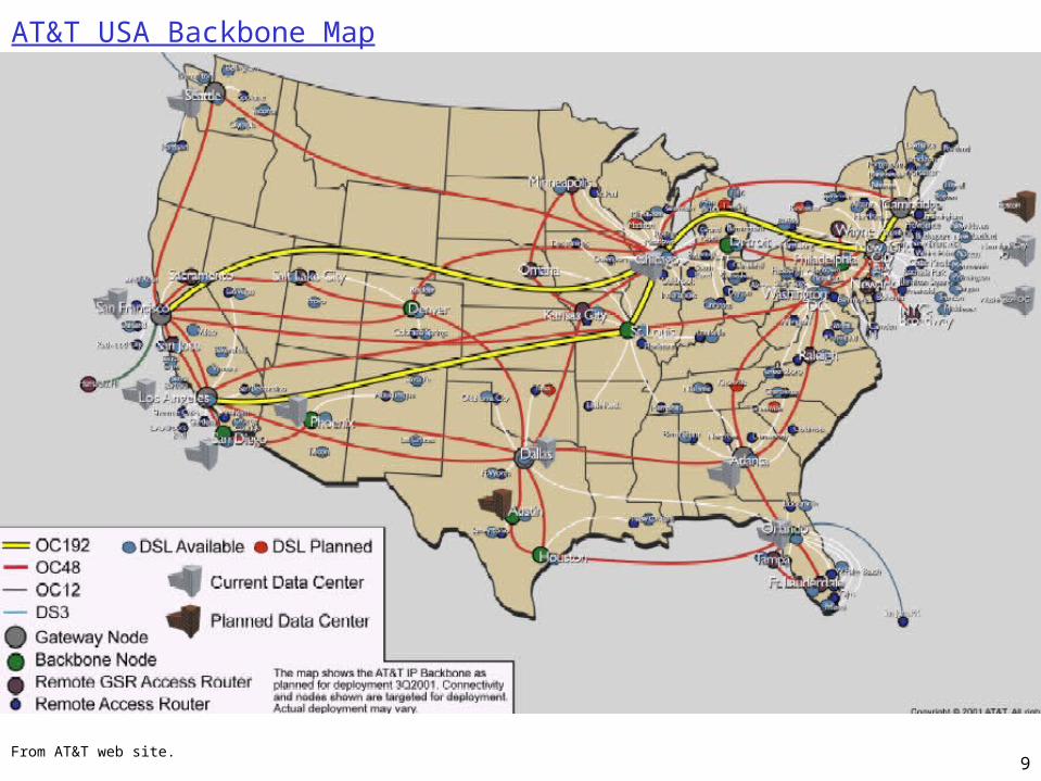
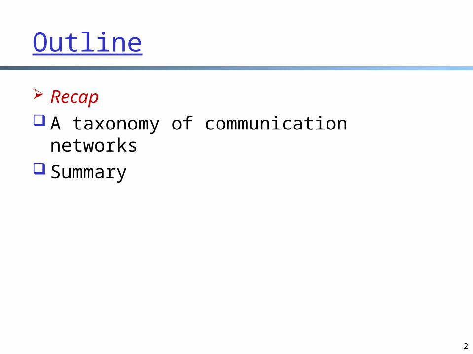
9From AT&T web site.
AT&T USA Backbone Map

10
Commercial Internet ISP Connectivity Roughly hierarchical
Divided into tiers Tier-1 ISPs are also called
backbone providers, e.g., AT&T, Verizon, Sprint, Level 3, Qwest
An ISP runs (private) Points of Presence (PoP) where its customers and other ISPs connect to it
ISPs also connect at (public) Network Access Point (NAP)
called public peering
11
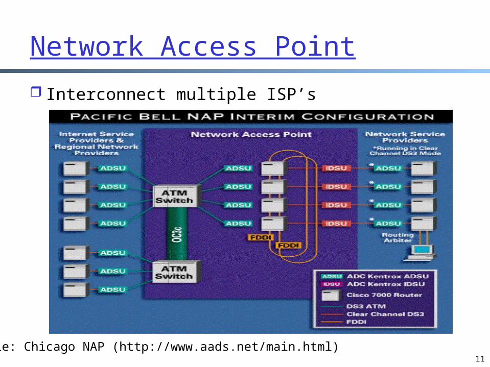
Network Access Point
Interconnect multiple ISP’s
Example: Chicago NAP (http://www.aads.net/main.html)

12
Outline
Admin. and recap A taxonomy of communication networks Summary

13
A Taxonomy of Communication Networks
So far we have looked at only the topology and physical connectivity of the Internet: a mesh of computers interconnected via various physical media
The fundamental question: how is data (the bits) transferred through a communication network?

14
Broadcast vs. Switched Communication Networks
Broadcast networks nodes share a common channel; information
transmitted by a node is received by all other nodes in the network
examples: TV, radio
Switched networks information is transmitted to a small sub-set (usually
only one) of the nodes
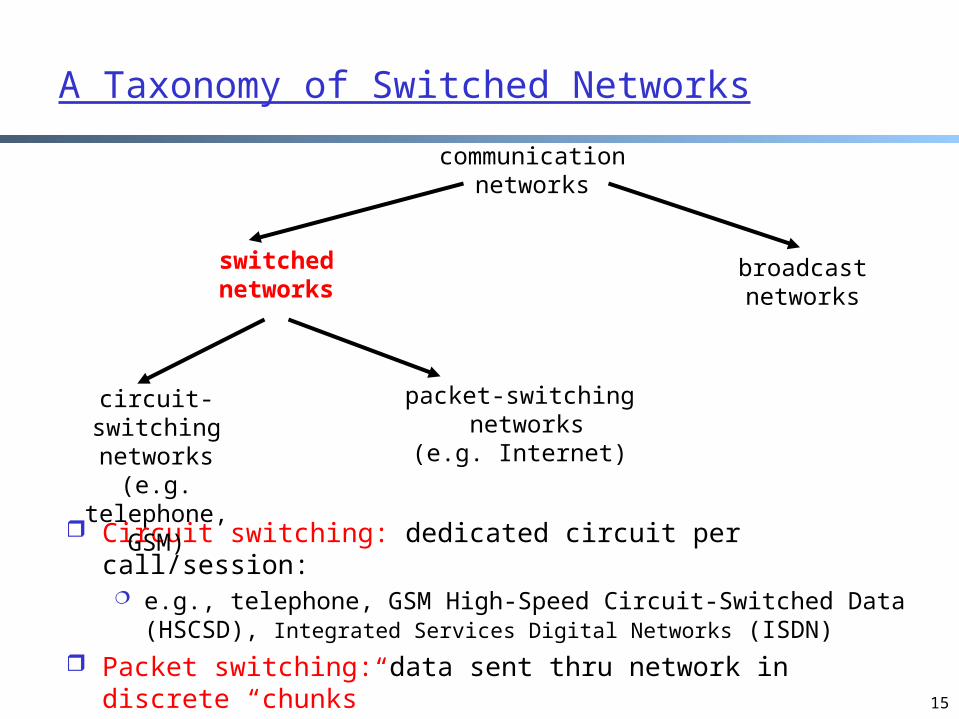
communication networks
switchednetworks
broadcastnetworks
15
Circuit switching: dedicated circuit per call/session: e.g., telephone, GSM High-Speed Circuit-Switched Data
(HSCSD), Integrated Services Digital Networks (ISDN) Packet switching: data sent thru network in discrete
“chunks” e.g., Internet, General Packet Radio Service (GPRS)
A Taxonomy of Switched Networks
communication networks
switchednetworks
broadcastnetworks
circuit-switchingnetworks
(e.g. telephone, GSM)
packet-switching networks
(e.g. Internet)

16
Outline
Admin. and review A taxonomy of communication networks
circuit switching networks packet switching networks circuit switching vs. packet switching datagram switching vs. virtual circuit
switching Summary
17
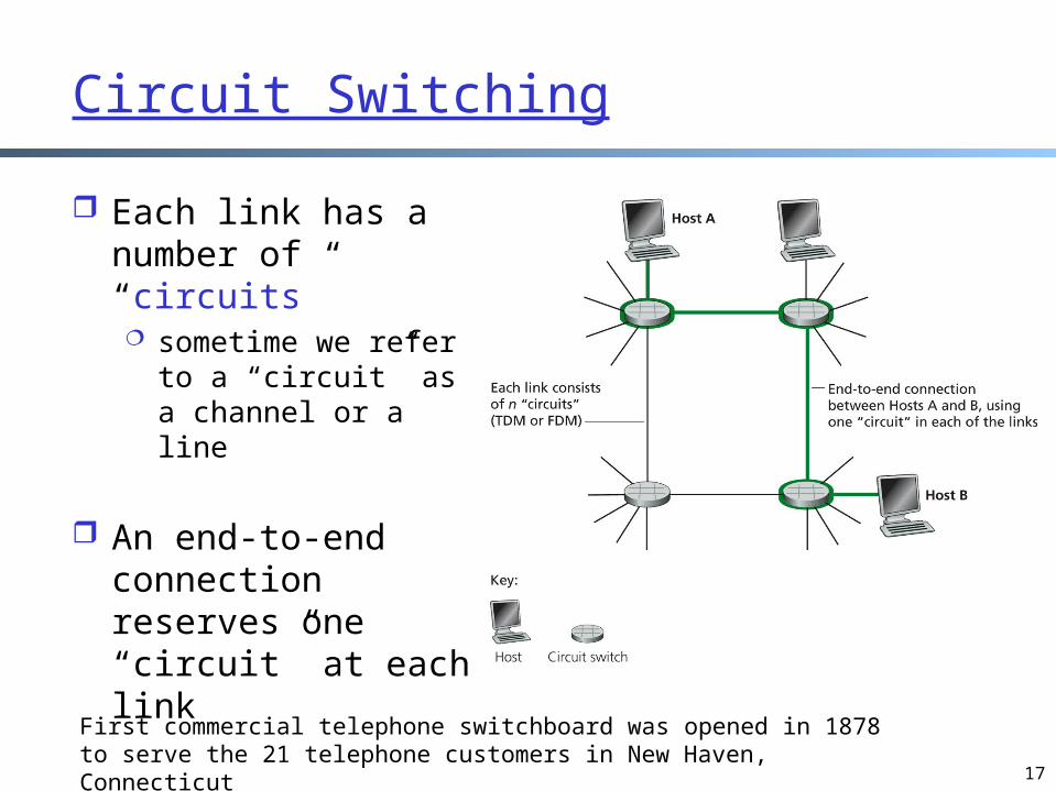
Circuit Switching
Each link has a number of “circuits” sometime we refer to
a “circuit” as a channel or a line
An end-to-end connection reserves one “circuit” at each link
First commercial telephone switchboard was opened in 1878 to serve the 21 telephone customers in New Haven, Connecticut
18
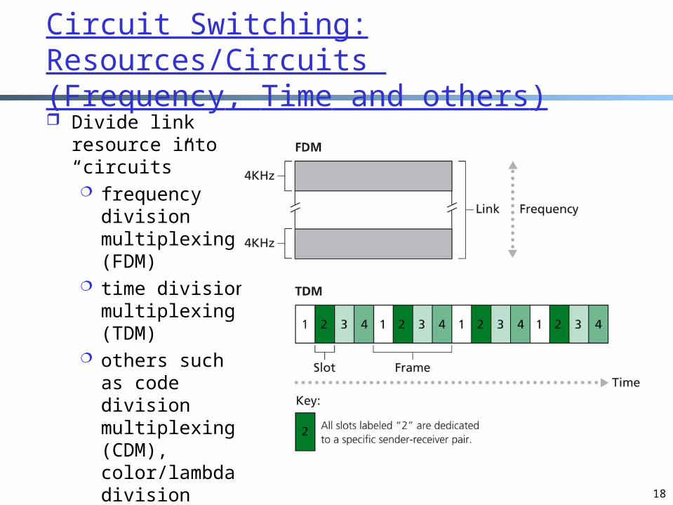
Circuit Switching: Resources/Circuits (Frequency, Time and others) Divide link
resource into “circuits” frequency
division multiplexing (FDM)
time division multiplexing (TDM)
others such as code division multiplexing (CDM), color/lambda division

19
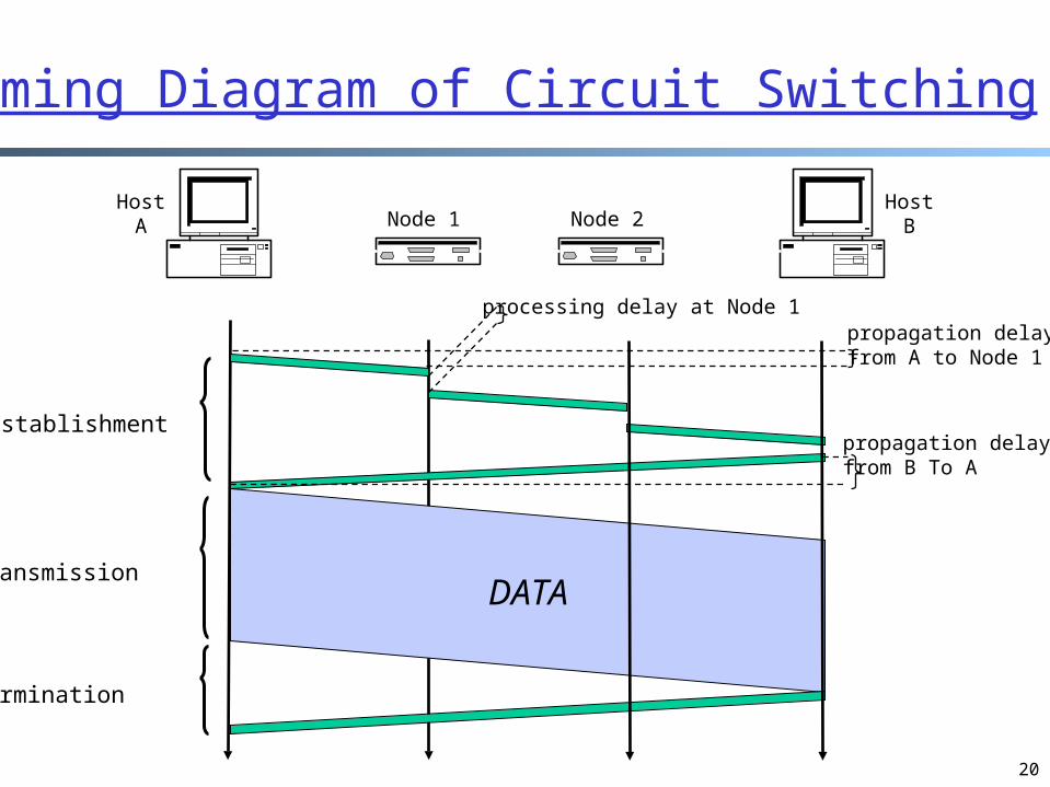
Circuit Switching: The Process
Three phases1. circuit establishment2. data transfer3. circuit termination
20
circuit establishment
DATA
data transmission
circuit termination
Host A Host BNode 1 Node 2
propagation delay from A to Node 1
propagation delay from B To A
processing delay at Node 1
Timing Diagram of Circuit Switching

21
Delay Calculation in Circuit Switched Networks
Transmission delay: R = reserved
bandwidth (bps) L = message length
(bits) time to send a packet
into link = L/R
Propagation delay: d = length of physical
link s = propagation speed
in medium (~2x10⁵ km/sec)
propagation delay = d/s
Propagation delay: delay for the first bit to go from a source to a destination
Transmission delay: time to pump data onto link at reserved rate
DATA
d/s
L/R
22
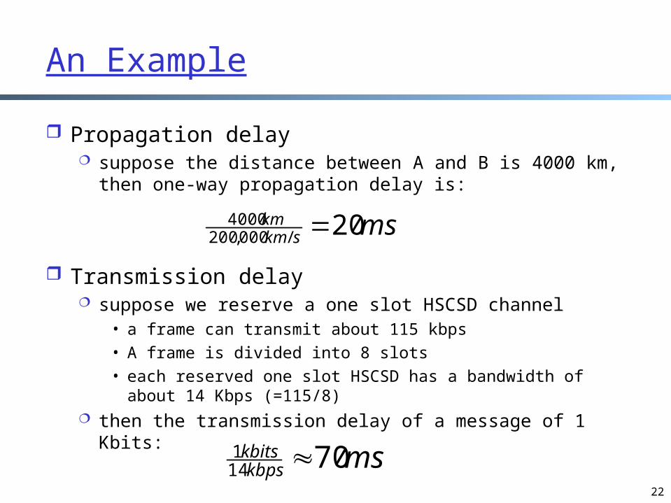
An Example
Propagation delay suppose the distance between A and B is 4000 km,
then one-way propagation delay is:
Transmission delay suppose we reserve a one slot HSCSD channel
• a frame can transmit about 115 kbps• A frame is divided into 8 slots• each reserved one slot HSCSD has a bandwidth of about
14 Kbps (=115/8) then the transmission delay of a message of 1 Kbits:
msskmkm 20/000,200
4000
mskbpskbits 7014
1

23
An Example (cont.) Suppose the setup message is very small, and the total
setup processing delay is 200 ms Then the delay to transfer a message of 1 Kbits from A to
B (from the beginning until host receives last bit) is:
ms33070202020020
DATA
20 + 200
20
20
70
24
Outline
Admin. and review A taxonomy of communication networks
circuit switching networks packet switching networks circuit switching vs. packet switching
Summary

25
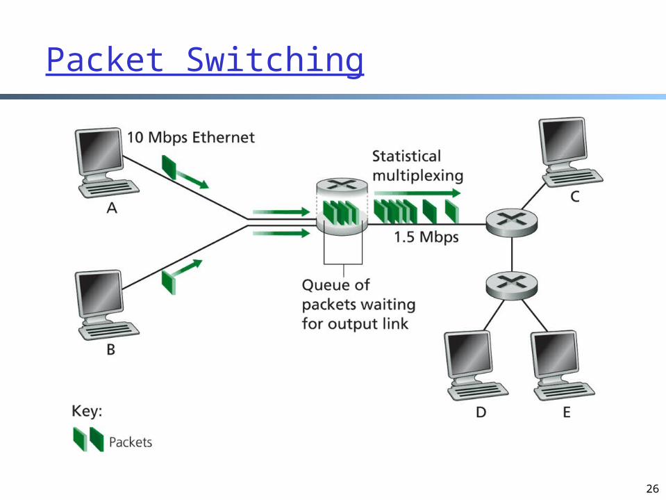
Packet Switching
Each end-to-end data flow (i.e., a sender-receiver pair) divided into packets
Packets have the following structure:
• header and trailer carry control information (e.g., destination address, check sum)
• where is the control information for circuit switching?• any analogy in life?
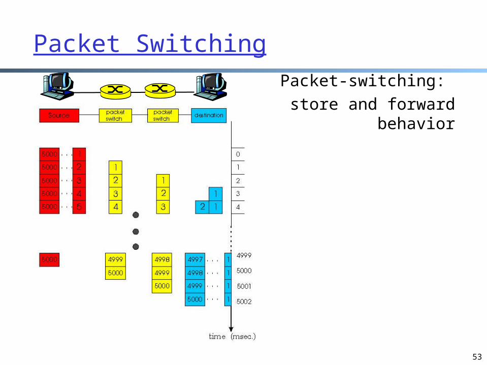
At each node the entire packet is received, processed (e.g., routing), stored briefly, and then forwarded to the next node; thus packet-switched networks are also called store-and-forward networks
Header Data Trailer
26
Packet Switching
27
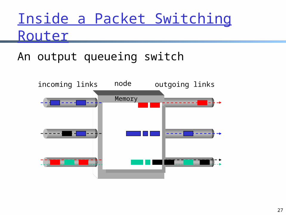
Inside a Packet Switching Router
An output queueing switch
incoming links outgoing linksnode
Memory
28
Packet Switching: Resources
Resources used as needed On its turn, a packet uses full link
bandwidth
29
Outline
Admin. and review A taxonomy of communication networks
circuit switching networks packet switching networks circuit switching vs. packet switching
Summary

30
Packet Switching vs. Circuit Switching
The early history of the Internet was a heated debate between Packet Switching and Circuit Switchingthe telephone network was the
dominant network
Need to compare packet switching with circuit switching

Circuit Switching vs. Packet Switching
31
circuit switching
packet switching
resource partitioned not partitioned
when using resource
use a single partition bandwidth
use whole link bandwidth
reservation/setup
need reservation (setup delay)
no reservation
resource contention
busy signal (session loss)
congestion (long delay and packet losses)
header no header per packet header
processing fast per packet processing
Key Issue to be Settled
All the other comparisons are easy to understand, a key debating issue was whether resource partition would be inefficient.
Tool used to analyze the issue: queueing theory
32

Analysis of Circuit-Switching Blocking (Busy) Time
Assume N circuits Session arrival: per second Session service rate: per second What is the percentage of time that a
new session is blocked?
33
For a demo of M/M/1, see: http://www.dcs.ed.ac.uk/home/jeh/Simjava/queueing/mm1_q/mm1_q.html
34
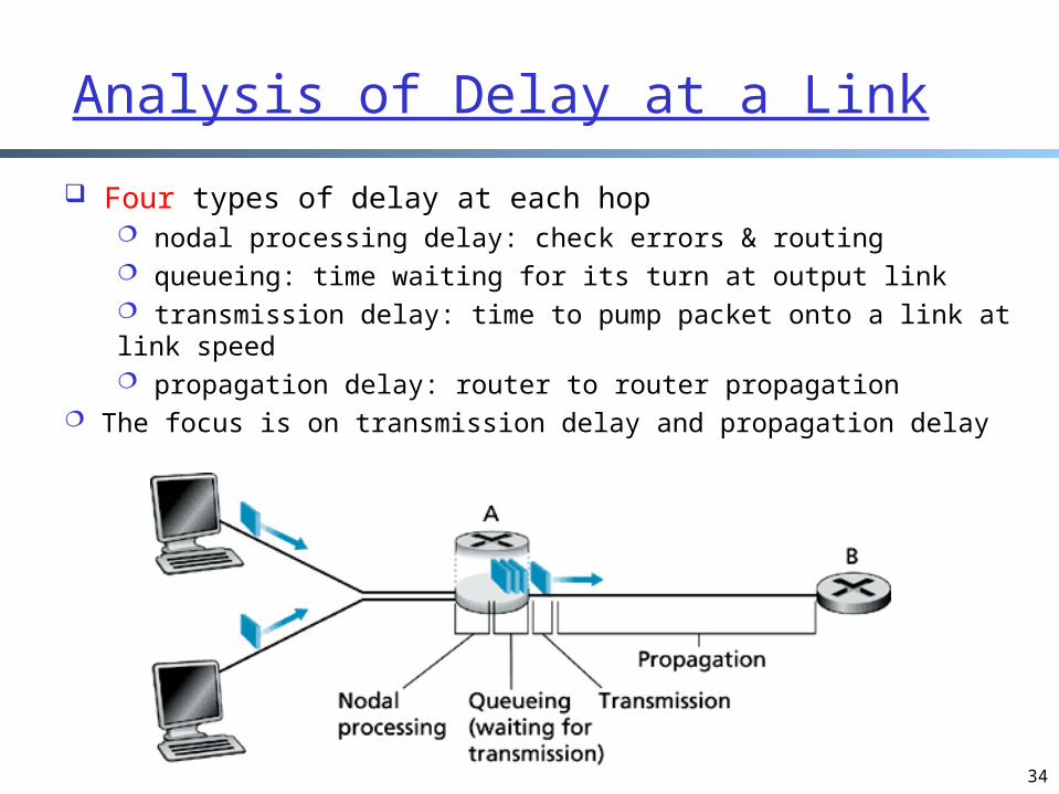
Analysis of Delay at a Link
Four types of delay at each hop nodal processing delay: check errors & routing queueing: time waiting for its turn at output link transmission delay: time to pump packet onto a link at link speed propagation delay: router to router propagation
The focus is on transmission delay and propagation delay

35
The Key Case: To Partition or not to Partition?
Case 1 (not reserve): all arrivals into a single link with rate R, what is the queueing delay + transmission delay?
Assume:R = link bandwidth (bps)L = average packet length (bits)a = average packet arrival rate
(pkt/sec)R/L = packet service rate (pkt/sec)
Case 2 (reserve): the arrivals are divided into n links with rate R/n each, what is the queueing delay + transmission delay?
Setup: n streams; each stream has an arrival rate of a/n
Comparison: each stream reserves 1/n bandwidth or not
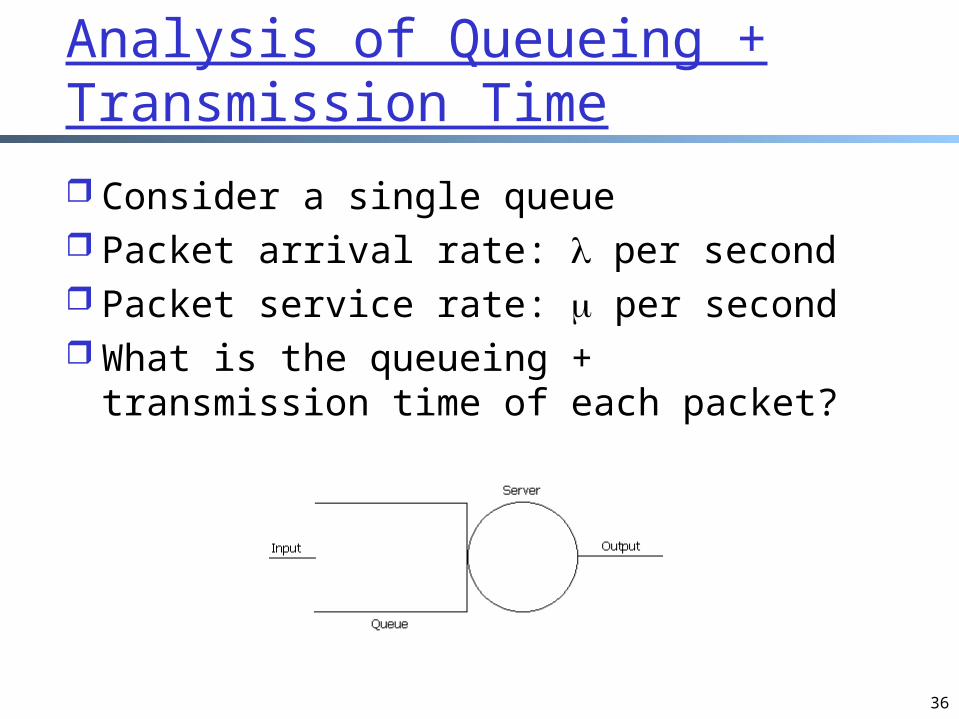
Analysis of Queueing + Transmission Time
Consider a single queue Packet arrival rate: per second Packet service rate: per second What is the queueing + transmission
time of each packet?
36
37
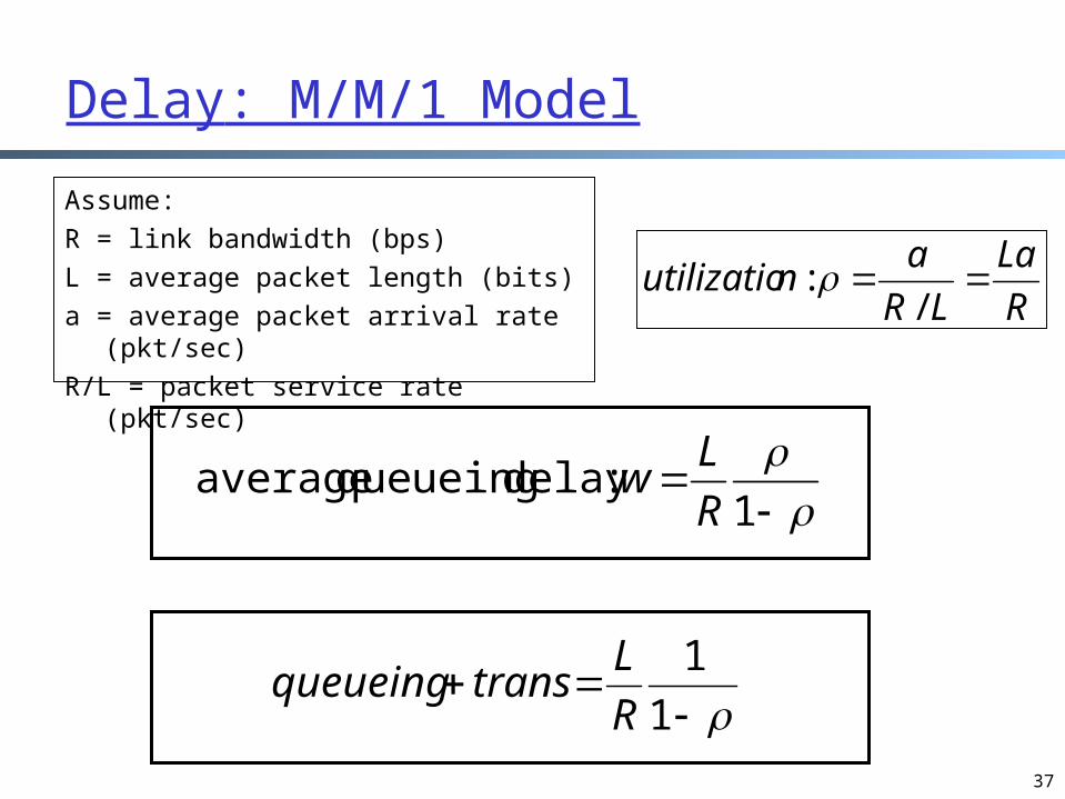
Delay: M/M/1 Model
1
:delay queueing averageR
Lw
Assume:R = link bandwidth (bps)L = average packet length (bits)a = average packet arrival rate
(pkt/sec)R/L = packet service rate (pkt/sec)
1
1
R
Ltransqueueing
R
La
LR
anutilizatio
/ :

38
Queueing Delay as A Function of Utilization
~ 0: average queueing delay small
-> 1: delay becomes large > 1: more “work” arriving
than can be serviced, average delay infinite !
Assume:R = link bandwidth (bps)L = packet length (bits)a = average packet arrival rate
(pkt/sec)R/L = packet service rate (pkt/sec)
R
La
LR
anutilizatio
/ :

39
Statistical Multiplexing Gain
Case 1 (not reserve): all arrivals into a single link with rate R
Assume:R = link bandwidth (bps)L = average packet length (bits)a = average packet arrival rate
(pkt/sec)R/L = packet service rate (pkt/sec)
Case 2 (reserve): the arrivals are divided into n links with rate R/n each
Setup: n streams; each stream has an arrival rate of a/n
Comparison: each stream reserves 1/n bandwidth or not
1
1
R
Ltransqueueing
1
1
R
nLtransqueueing
any analogy in life?

40
Packet Switching vs. Circuit Switching
One of the major issues facing the Internet: How to provide circuit-like behavior (in terms of quality of service)? virtual circuit switching is originally mainly for
routing efficiency
bandwidth guarantees needed for audio/video apps
still an unsolved problem

41
Outline
Admin. and review A taxonomy of communication networks
circuit switching networks packet switching networks circuit switching vs. packet switching routing in packet switching networks
Summary

42
A Taxonomy of Packet-Switched Networks According to Routing
Goal: move packets among routers from source to destination we’ll study routing algorithms later in the course
Two types of packet switching datagram network
• each packet of a flow is switched independently
virtual circuit network: • all packets from one flow are sent along a pre-established
path (= virtual circuit)

43
Datagram Packet Switching
Example: IP networks Each packet is independently switched
each packet header contains complete destination address
receiving a packet, a router looks at the packet’s destination address and searches its current routing table to determine the possible next hops, and pick one
Discussions: an example of datagram-style communication in
daily life? advantages of datagram switching? potential problems of packet switching?
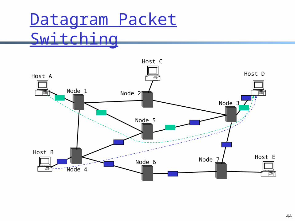
44
Host A
Host BHost E
Host D
Host C
Node 1 Node 2
Node 3
Node 4
Node 5
Node 6 Node 7
Datagram Packet Switching
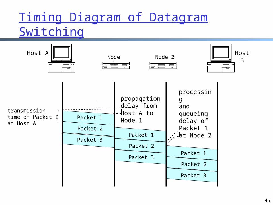
45
Packet 1
Packet 2
Packet 3
Packet 1
Packet 2
Packet 3
Packet 1
Packet 2
Packet 3
processing and queueing delay of Packet 1 at Node 2
Host A Host BNode
1Node 2
propagationdelay fromHost A to Node 1
transmission time of Packet 1at Host A
Timing Diagram of Datagram Switching

46
Virtual-Circuit Packet Switching
Example: Asynchornous Transfer Mode (ATM) networks; Multiple Label Packet Switching (MPLS) in IP networks
Hybrid of circuit switching and datagram switching each packet carries a short
tag (virtual-circuit (VC) #); tag determines next hop
fixed path determined at Virtual Circuit setup time, remains fixed thru flow
routers maintain per-flow state
• what state do routers maintain for datagram switching?
Incoming Interface
Incoming VC#
Outgoing Interface
Outgoing VC#
1 12 2 22
1 16 3 1
2 12 3 22
…
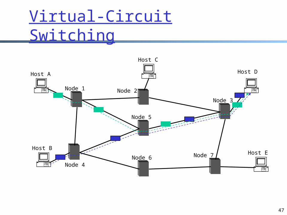
47
Host A
Host BHost E
Host D
Host C
Node 1 Node 2
Node 3
Node 4
Node 5
Node 6 Node 7
Virtual-Circuit Switching
48
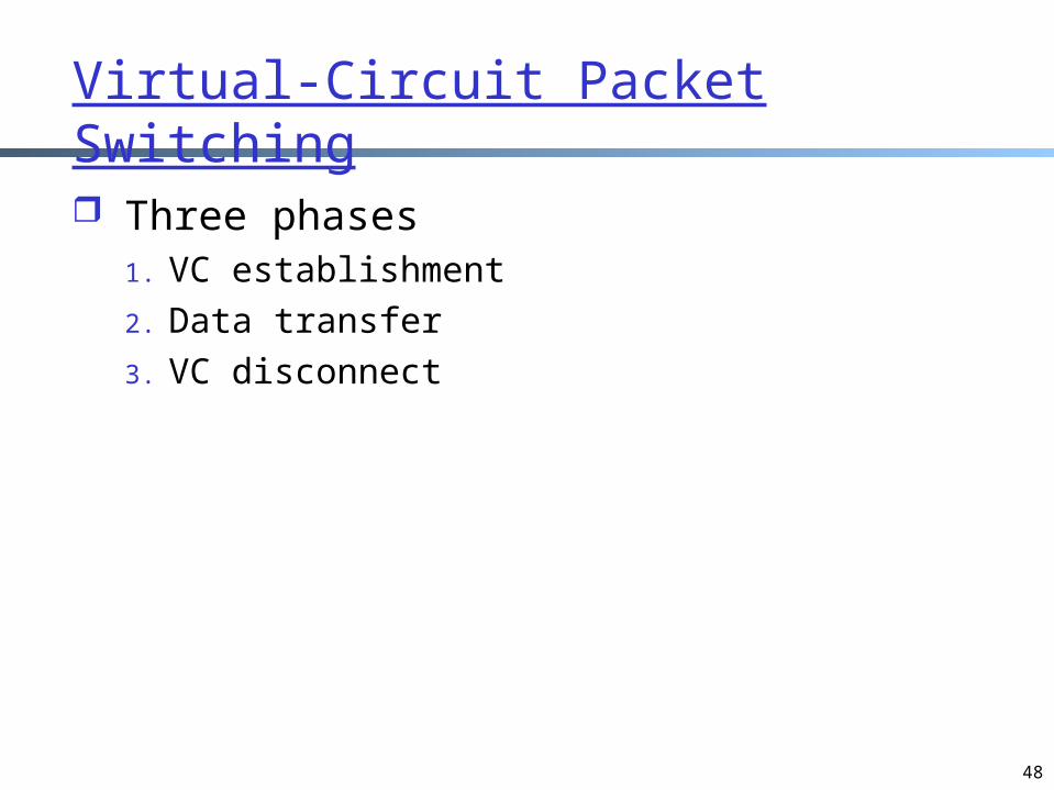
Virtual-Circuit Packet Switching
Three phases 1. VC establishment2. Data transfer3. VC disconnect

49
Packet 1
Packet 2
Packet 3
Packet 1
Packet 2
Packet 3
Packet 1
Packet 2
Packet 3
Host 1 Host 2Node
1Node
2
propagation delay between Host 1 and Node 1VC
establishment
VCtermination
datatransfer
Timing Diagram of Virtual-Circuit Switching
50
Discussion: Datagram Switching vs. Virtual Circuit Switching
What are the benefits of datagram switching over virtual circuit switching?
What are the benefits of virtual circuit switching over datagram switching?

51
Summary of the Taxonomy of Communication Networks
circuit-switchednetwork
communication network
switchednetwork
broadcastcommunication
packet-switched network
datagram network
virtual circuit network

52
Backup Slides
53
Packet SwitchingPacket-switching:
store and forward behavior

54
Connection-Oriented Service
Goal: data transfer between end sys.
handshaking: setup (prepare for) data transfer ahead of time Hello, hello back
human protocol set up “state” in two
communicating hosts
TCP - Transmission Control Protocol Internet’s connection-
oriented service
TCP service [RFC 793] reliable, in-order byte-
stream data transfer loss: acknowledgements
and retransmissions
flow control: sender won’t overwhelm
receiver
congestion control: senders “slow down
sending rate” when network congested
55
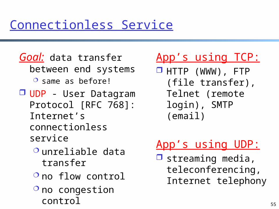
Connectionless Service
Goal: data transfer between end systems same as before!
UDP - User Datagram Protocol [RFC 768]: Internet’s connectionless service unreliable data
transfer no flow control no congestion
control
App’s using TCP: HTTP (WWW), FTP
(file transfer), Telnet (remote login), SMTP (email)
App’s using UDP: streaming media,
teleconferencing, Internet telephony

56
Relationship Between Switching Techniques and End Host Services
End hosts determine end host services: connection-oriented or connectionless what an application wants
Network service providers determine network services: circuit-switching, packet switching, datagram switching, or virtual circuit switching how the ISP builds their networks
57
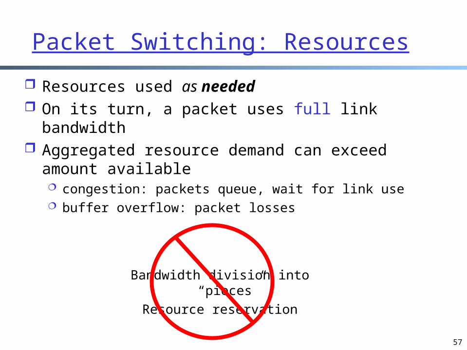
Packet Switching: Resources
Resources used as needed On its turn, a packet uses full link bandwidth Aggregated resource demand can exceed amount
available congestion: packets queue, wait for link use buffer overflow: packet losses
Bandwidth division into “pieces”
Resource reservation
58
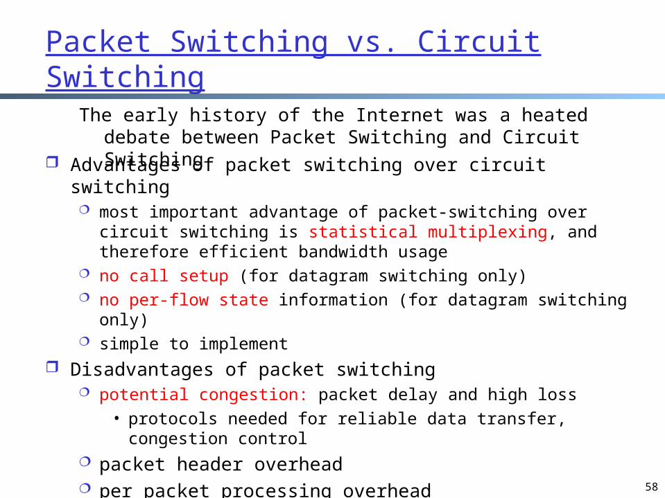
Packet Switching vs. Circuit Switching
Advantages of packet switching over circuit switching most important advantage of packet-switching over circuit
switching is statistical multiplexing, and therefore efficient bandwidth usage
no call setup (for datagram switching only) no per-flow state information (for datagram switching only) simple to implement
Disadvantages of packet switching potential congestion: packet delay and high loss
• protocols needed for reliable data transfer, congestion control
packet header overhead per packet processing overhead
Questions: why does the current Internet use datagram?
The early history of the Internet was a heated debate between Packet Switching and Circuit Switching

59
Statistical Multiplexing
Case 1 (not reserve): all arrivals into a single link with rate R, what is the queueing delay + transmission delay?
Assume:R = link bandwidth (bps)L = average packet length (bits)a = average packet arrival rate
(pkt/sec)R/L = packet service rate (pkt/sec)
1R
Lw
Case 2 (reserve): the arrivals are divided into n links with rate R/n each, what is the queueing delay + transmission delay?
Setup: N flows; each flow has an arrival rate of a/n
Comparison: each flow reserves 1/n bandwidth or not

60
Queueing Delay: Kendall Notation Arrival/Service/NumberServers
E.g., M/M/1, M/D/1
Arrival process: the inter-arrival time D: fixed/deterministic inter-arrival time M: Markov, i.e., in each unit of time, where small,
the probability of exactly one arrival is , where is called arrival rate
Service process: the service time D: fixed/deterministic service time M: Markov, i.e., in each unit of time, where small,
the probability of finish serving is , where is called service rate
For a demo of M/M/1, see: http://www.dcs.ed.ac.uk/home/jeh/Simjava/queueing/mm1_q/mm1_q.html

61
Queueing Delay: M/M/1 Model
1
:delay queueing averageR
Lw
Assume:R = link bandwidth (bps)L = average packet length (bits)a = average packet arrival rate
(pkt/sec)R/L = packet service rate (pkt/sec)
12
1 :delay queueing average
R
LwA more realistic model of
modern routers: M/D/1