
1/ 46 Pedro Company - UJI eng.pdf · 2/ 46 Pedro Company Napoli, June, 4th 2007 Tools for easing...
46
1 / 46 Napoli, June, 4th 2007
Transcript of 1/ 46 Pedro Company - UJI eng.pdf · 2/ 46 Pedro Company Napoli, June, 4th 2007 Tools for easing...

1 / 46Pedro Company
Napoli, June, 4th 2007

2 / 46Pedro Company
Napoli, June, 4th 2007
Tools for easing theTools for easing theHumanHuman--Computer InteractionComputer Interaction
during Virtual Assembly Process,during Virtual Assembly Process,by way of Sketchby way of Sketch--Based InterfacesBased Interfaces
REGEO
Pedro Company

3 / 46Pedro Company
Napoli, June, 4th 2007Summary
I shall introduce my presentation by reading the titlein reverse order,as I am going to introduce
Sketch-based interfaces
Their potential role duringvirtual assembly process…
… and the advantages this could addto the human-computer interactionalong a computer-aided designdesign--forfor--assemblyassembly process
Which is our current research goal!
CAISBIMGeom. Reconst.AnnotationsNext step
AntecedentsSummary
Conclusions

4 / 46Pedro Company
Napoli, June, 4th 2007
Our work began to be fruitful since 2000
Some antecedents of the group
Current situation can be know visiting:www.regeo.uji.eswww.regeo.uji.es
REGEO
REGEO was born in 1994CAISBIMGeom. Reconst.AnnotationsNext step
AntecedentsSummary
Conclusions

5 / 46Pedro Company
Napoli, June, 4th 2007CAI
…computers are still unpracticalduring conceptual stepsof industrial products design...
...because CAD applicationsare unable to work withconfuse,poorly structured andincomplete ideas.
To sum up our research, we can state that…
CAISBIMGeom. Reconst.AnnotationsNext step
AntecedentsSummary
Conclusions
6 / 46Pedro Company
Napoli, June, 4th 2007CAI
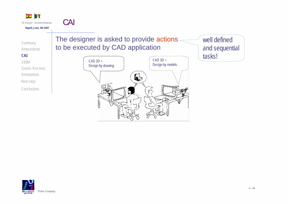
The designer is asked to provide actionsto be executed by CAD application
well definedand sequential tasks!
CAD 3D =Design by models
CAD 2D =Design by drawing
CAISBIMGeom. Reconst.AnnotationsNext step
AntecedentsSummary
Conclusions

7 / 46Pedro Company
Napoli, June, 4th 2007CAI
The designer is asked to provide actionsto be executed by CAD application
And this is not a good strategywhile the designer is trying to fix visions
The TOOL is conditioning the TASK!
Poorly-defined,non-sequential ideas!
CAD 3D =Design by models
CAD 2D =Design by drawing
well definedand sequential tasks!CAI
SBIMGeom. Reconst.AnnotationsNext step
AntecedentsSummary
Conclusions

8 / 46Pedro Company
Napoli, June, 4th 2007CAI
…to differentiate from current CAD application
We name themCAI applications (Computer-Aided Ideation)...
design and implementcomputer applications
aimed athelping the designers
in the conceptual design step
So, our goal isCAISBIMGeom. Reconst.AnnotationsNext step
AntecedentsSummary
Conclusions

9 / 46Pedro Company
Napoli, June, 4th 2007CAI
¡To upgrade from CAD to CAI,the language must become “graphic”,
in the sense of non-sequential!
¡Many evidences support that
engineering sketches is such a graphic language
aimed at enhancing creativity!
CAISBIMGeom. Reconst.AnnotationsNext step
AntecedentsSummary
Conclusions

10 / 46Pedro Company
Napoli, June, 4th 2007
Butcomputers are blindto engineering sketches!
SBIM
So, new computer tools are required!
The scientific ambit aimed at solving this problem is known as:
SBIM(SKETCH-BASED INTERFACES AND MODELING)
CAISBIMGeom. Reconst.AnnotationsNext step
AntecedentsSummary
Conclusions

11 / 46Pedro Company
Napoli, June, 4th 2007SBIM
SBIM includes three main areas, and different sub-areas:
Document image processing
SBIM
SketchUnderstanding
3DModeling
Input &Interaction
Editing &Beautification
On-lineBatch
RegularitiesSymbolsAutomatic
Interactive
Knowledge-based
interpretation
Interactive
Template Matching
3D Reconstruction
Menu-driven
Gesture-based
Single view
Multiple views
SegmentationTextual processingGraphics processing
Textual interpretationGraphics interpretationGlobal interpretation
Primitives
Menu-drivenGesture-based
CAISBIMGeom. Reconst.AnnotationsNext step
AntecedentsSummary
Conclusions

12 / 46Pedro Company
Napoli, June, 4th 2007Geometrical reconstruction
We were first interested in theautomatic 3D modelling sub-area SBIM
SketchUnderstanding
3DModeling
Knowledge-based interpretation
Interactive
Template Matching
3D Reconstruction CAISBIMGeom. Reconst.AnnotationsNext step
AntecedentsSummary
Conclusions

13 / 46Pedro Company
Napoli, June, 4th 2007Geometrical reconstruction
We were first interested in theautomatic 3D modelling sub-area
GEOMETRICAL RECONSTRUCTIONthe discipline aimed at automatic, or semi-automatically,
obtainingthree-dimensional geometrical models
from two-dimensional line-drawings or sketches
So, we began to work in:
SBIM
SketchUnderstanding
3DModeling
Knowledge-based interpretation
Interactive
Template Matching
3D Reconstruction CAISBIMGeom. Reconst.AnnotationsNext step
AntecedentsSummary
Conclusions

14 / 46Pedro Company
Napoli, June, 4th 2007
We have developed a system that outputs 3D models when the user inputs 2D sketches:
Geometrical reconstruction
CAISBIMGeom. Reconst.AnnotationsNext step
AntecedentsSummary
Conclusions

15 / 46Pedro Company
Napoli, June, 4th 2007
Our main contributions have been centred in:
Geometrical reconstruction
1
234
56
78
9
10
12
11
1
234
56
78
9
10 11
12
New approach to reconstruct polyhedral shapesof a particular class named “quasi-normalons”
Polyhedral that do not loose any vertex when removing edges non-parallel to the three main orthogonal directions
CAISBIMGeom. Reconst.AnnotationsNext step
AntecedentsSummary
Conclusions

16 / 46Pedro Company
Napoli, June, 4th 2007Geometrical reconstruction
Beautification of the line-drawing obtained from the sketch,to avoid “tangled”shapes during reconstruction
b) On-line line drawing
c) Off-line tidying
e) 3D “tangled” shape
BA
f) 3D shape
d) Off-line parallelism and
collinearity tidying
a) Input sketch
CAISBIMGeom. Reconst.AnnotationsNext step
AntecedentsSummary
Conclusions

17 / 46Pedro Company
Napoli, June, 4th 2007Geometrical reconstruction
Early detection of symmetry in the 2D line-drawing,
and improvement of the reconstruction process through symmetry regularity
CAISBIMGeom. Reconst.AnnotationsNext step
AntecedentsSummary
Conclusions
18 / 46Pedro Company
Napoli, June, 4th 2007Interpreting annotations
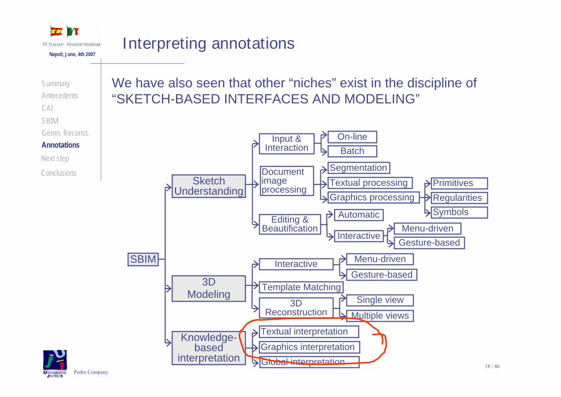
We have also seen that other “niches” exist in the discipline of “SKETCH-BASED INTERFACES AND MODELING”
Document image processing
SBIM
SketchUnderstanding
3DModeling
Input &Interaction
Editing &Beautification
On-lineBatch
RegularitiesSymbolsAutomatic
Interactive
Knowledge-based
interpretation
Interactive
Template Matching
3D Reconstruction
Menu-driven
Gesture-based
Single view
Multiple views
SegmentationTextual processingGraphics processing
Textual interpretationGraphics interpretationGlobal interpretation
Primitives
Menu-drivenGesture-based
CAISBIMGeom. Reconst.AnnotationsNext step
AntecedentsSummary
Conclusions

19 / 46Pedro Company
Napoli, June, 4th 2007
One of our current research lines is aimed at Interpreting Annotated Engineering Drawings
Make concentricMake parallelMake perpendicular
CAI systems should be ableto interpret designers annotations
Reason
Interpreting annotations
Goal
Engineering designersannotate their designs with symbols
Approach
Capture and record the data
Separate annotation datafrom drawing data
Interpret annotations
Apply the annotationsto create the model
CAISBIMGeom. Reconst.AnnotationsNext step
AntecedentsSummary
Conclusions

20 / 46Pedro Company
Napoli, June, 4th 2007
Currently, we can interpret:
Four types of strokes
Twelve annotations
Interpreting annotations
CAISBIMGeom. Reconst.AnnotationsNext step
AntecedentsSummary
Conclusions

21 / 46Pedro Company
Napoli, June, 4th 2007
Currently, we can interpret:
Four types of strokes
Twelve annotations
Segments
Arcs
Circles
Ellipses
Vi
Vi+1
I
α+π/2α
r
C
R
M
Vi
Vi+1Intersection point
α+π/2
α
s
rC
Separate entities are obtained from a simple stroke!
Interpreting annotations
CAISBIMGeom. Reconst.AnnotationsNext step
AntecedentsSummary
Conclusions

22 / 46Pedro Company
Napoli, June, 4th 2007
Four types of strokes
Twelve annotations
Annotations are recognised with 90% or better accuracy
Perpendicular
Dimension
Horizontal ParallelVertical
Extrude
Diametricdimension
Rotate rightRotate left
ConcentricMaketangential
Erase
Interpreting annotations
Currently, we can interpret:
CAISBIMGeom. Reconst.AnnotationsNext step
AntecedentsSummary
Conclusions

23 / 46Pedro Company
Napoli, June, 4th 2007
Currently, we are limited to reconstruct isolated parts.
Next step
But, in our pursuit ofapplying annotationsto create models…
Capture and record the data
Separate annotation datafrom drawing data
Interpret annotations
Apply the annotationsto create the model
… we want to be able tocreate assemblies from sketches!
CAISBIMGeom. Reconst.AnnotationsNext step
AntecedentsSummary
Conclusions

24 / 46Pedro Company
Napoli, June, 4th 2007
Our vision isto define and implement a set of symbols
that can help a CAI systemto assemble 3D models obtained from 2D sketches.
Next step
The idea was first presented at:
Saorín J.L., Contero M., Naya F. y Conesa J. (2003). Interfaz gestual para la definición de condiciones de ensamblaje para la generación de maquetas digitales. Proceedings of the VII International Congress on Project Engineering, (ISBN: 84-9769-037-0), p. 124.
http://www.regeo.uji.es/publicaciones/CIIP03.pdf
CAISBIMGeom. Reconst.AnnotationsNext step
AntecedentsSummary
Conclusions

25 / 46Pedro Company
Napoli, June, 4th 2007
The basic guidelines of our approach should be:
Next step
The symbols must be sketched themselves, as part of a “natural” design process
The meaning of the symbols must be “robust”
The symbols should overtake the faultsof current sets of CAD operations
D.O.F6
D.O.F0
D.O.F2
D.O.F4
CAISBIMGeom. Reconst.AnnotationsNext step
AntecedentsSummary
Conclusions
In the sense of being understood without mistakesby the geometrical engine in charge of assembling the parts
They are neither full usability-driven,nor full manufacturability-driven

26 / 46Pedro Company
Napoli, June, 4th 2007
What is wrong with current CAD applications?
Next step
SolidEdge: originally developed and release by Intergraph in 1996using the ACIS geometric modeling kernel
it later changed to using the Parasolid kernel
CAISBIMGeom. Reconst.AnnotationsNext step
AntecedentsSummary
Conclusions

27 / 46Pedro Company
Napoli, June, 4th 2007
Assembly Modelling is the technology and methods used by CAD and other computer software systems to handle multiple files that represent components within a product.
Next step
Components can be positionedwithin the product assembly using:
Mating conditions are definitions of the relative position of components between each other.For example alignment of axis of two holes or distance of two faces from one another.
The final position of al components based on these relationships is calculated using a geometry constraint engine built into the CAD or visualization package.
absolute coordinate placement methods
mating conditions.
CAISBIMGeom. Reconst.AnnotationsNext step
AntecedentsSummary
Conclusions

28 / 46Pedro Company
Napoli, June, 4th 2007
In fact, some mating conditions tools assist the userto get an intuitive and friendly set of constraints:
Next step
As users place parts in an assembly, assembly relationships position new parts relative to parts already in the assembly.
Starting with v8 (2000),Solid Edge also has aFlashFit optionthat can reducesteps requiredto position parts.
There are several relationship types for positioning partsrelative to each other.
CAISBIMGeom. Reconst.AnnotationsNext step
AntecedentsSummary
Conclusions

29 / 46Pedro Company
Napoli, June, 4th 2007Next step
However, we can find two main drawbacks:
Only finished parts can be assembled
Assembly relationships still require taxonomies
CAISBIMGeom. Reconst.AnnotationsNext step
AntecedentsSummary
Conclusions

30 / 46Pedro Company
Napoli, June, 4th 2007
Only complete and consistent partscan be assembled:
Next step
Detailed design of parts is an assembly pre-requisite!
CAD assembly sub-systems requirestandard CAD parts input
CAISBIMGeom. Reconst.AnnotationsNext step
AntecedentsSummary
Conclusions

31 / 46Pedro Company
Napoli, June, 4th 2007
Our vision is creating a sketch-based environment …
Next step
In other words:
… able to assemble different parts…
… that are not yet fully defined.
CAISBIMGeom. Reconst.AnnotationsNext step
AntecedentsSummary
Conclusions
Assemble conceptual designs of parts!

32 / 46Pedro Company
Napoli, June, 4th 2007
Current CAD applicationsmerge different kind of assembling tools:
Next step
some are oriented to functionality and manufacturability
but other that are “geometry-driven”
CAISBIMGeom. Reconst.AnnotationsNext step
AntecedentsSummary
Conclusions

33 / 46Pedro Company
Napoli, June, 4th 2007
Our vision is developing anew set of mating conditions:
Next step
Valid to assemble sketched parts
Containing design intents, instead of geometrical constraints
Useful as input information for tolerancing purposes
CAISBIMGeom. Reconst.AnnotationsNext step
AntecedentsSummary
Conclusions

34 / 46Pedro Company
Napoli, June, 4th 2007
Our vision is developing anew set of mating conditions:
Next step
Valid to assemble sketched parts
Containing design intents, instead of geometrical constraints
Useful as input information for tolerancing purposes tolerances should ensure that
parts within tolerance specification are:
functionally equivalent
interchangeable in assembly
We believe that this makes sense, because…
CAISBIMGeom. Reconst.AnnotationsNext step
AntecedentsSummary
Conclusions

35 / 46Pedro Company
Napoli, June, 4th 2007
FROOM
Next step
Some tolerancing representation and specificationapproaches seem more promising than others:
…but we have found important problems still unsolved…
CAISBIMGeom. Reconst.AnnotationsNext step
AntecedentsSummary
Conclusions
T.T.R.S.Clement A., Valade C. and Riviere A., 1997, The TTRSs: 13 oriented constraints for dimensioning, tolerancing and inspection. In P. Ciarlini, M. G. Cox, F. Pavese, and D. Ritcher (eds.), Advanced Mathematical Tools in Metrology III (World Scientific Publishing Company), pp. 24-42.
Salomons, O. W., 1995, Computer support in the design of mechanical products. PhD thesis, University of Twente, The Netherlands, available at http://www.pt.wb.utwente.nl/staff/otto/thesis/.
Clement A., Riviere A., Serre P. and Valade C., 1998, The TTRSs: 13 oriented constraints for dimensioning and tolerancing. In H. A. ElMaraghy(ed.), Geometric Design Tolerancing: Theories, Standards and Applications, pp. 122-131, presented at the 5th CIRP Seminar on Computer-Aided Tolerancing, Toronto, Canada.

36 / 46Pedro Company
Napoli, June, 4th 2007Next step
Current tolerancing standards and practicesmust be tightened (formalized) considerablyif we are to represent tolerancing information
in computer-based geometric systemsin a form suitable for automatic tolerance analysis;
automatic planning of manufacturing, assembly, and inspection operations;
and design and production activities.
The above paragraph comes from Requicha (1983)
But it was cited by Zhang and Huq… in 1993!
Zhang H.C. and Huq M.E. (1993) Tolerancing techniques: the state-of-the-art. International Journal of Production Research, 30 (9), 2111-2135.
Requicha A.A.G. (1983), Toward a theory of geometric tolerancing. The international Journal of Robotics Research, 2 (4), 45-60.
CAISBIMGeom. Reconst.AnnotationsNext step
AntecedentsSummary
Conclusions

37 / 46Pedro Company
Napoli, June, 4th 2007Next step
“standardization of the interfacingof the geometric modeller
with other components of computer integrated manufacturing is needed”
In its state-of-the-art, Zhang and Huq,cited a former workby Ali et al (1988)to assert that:
Zhang H.C. and Huq M.E. (1993) Tolerancing techniques: the state-of-the-art. International Journal of Production Research, 30 (9), 2111-2135.
CAISBIMGeom. Reconst.AnnotationsNext step
AntecedentsSummary
Conclusions
38 / 46Pedro Company
Napoli, June, 4th 2007
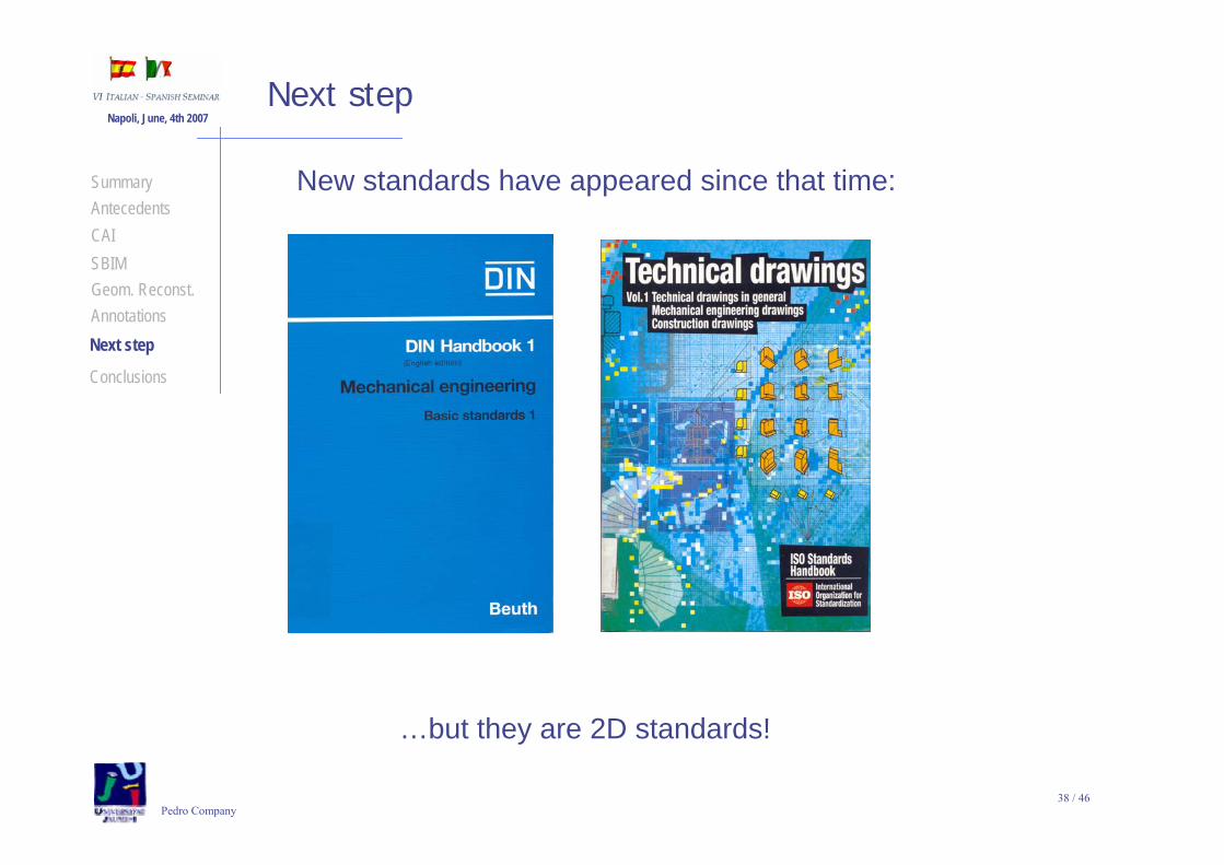
New standards have appeared since that time:
Next step
…but they are 2D standards!
CAISBIMGeom. Reconst.AnnotationsNext step
AntecedentsSummary
Conclusions

39 / 46Pedro Company
Napoli, June, 4th 2007
A new state-of-the-art appeared in 2002.
Next step
Although geometric tolerancing addresses the weaknessand intrinsic ambiguities of parametric tolerancing,
it still poses its own weakness,mainly due to its informal wayof defining the core concepts
Hong Y.S. and Chang T.C. (2002) A comprehensive review of tolerancingresearch. International Journal of Production Research, 40 (11), 2425-2459.
And the problem was quoted again:
CAISBIMGeom. Reconst.AnnotationsNext step
AntecedentsSummary
Conclusions
40 / 46Pedro Company
Napoli, June, 4th 2007
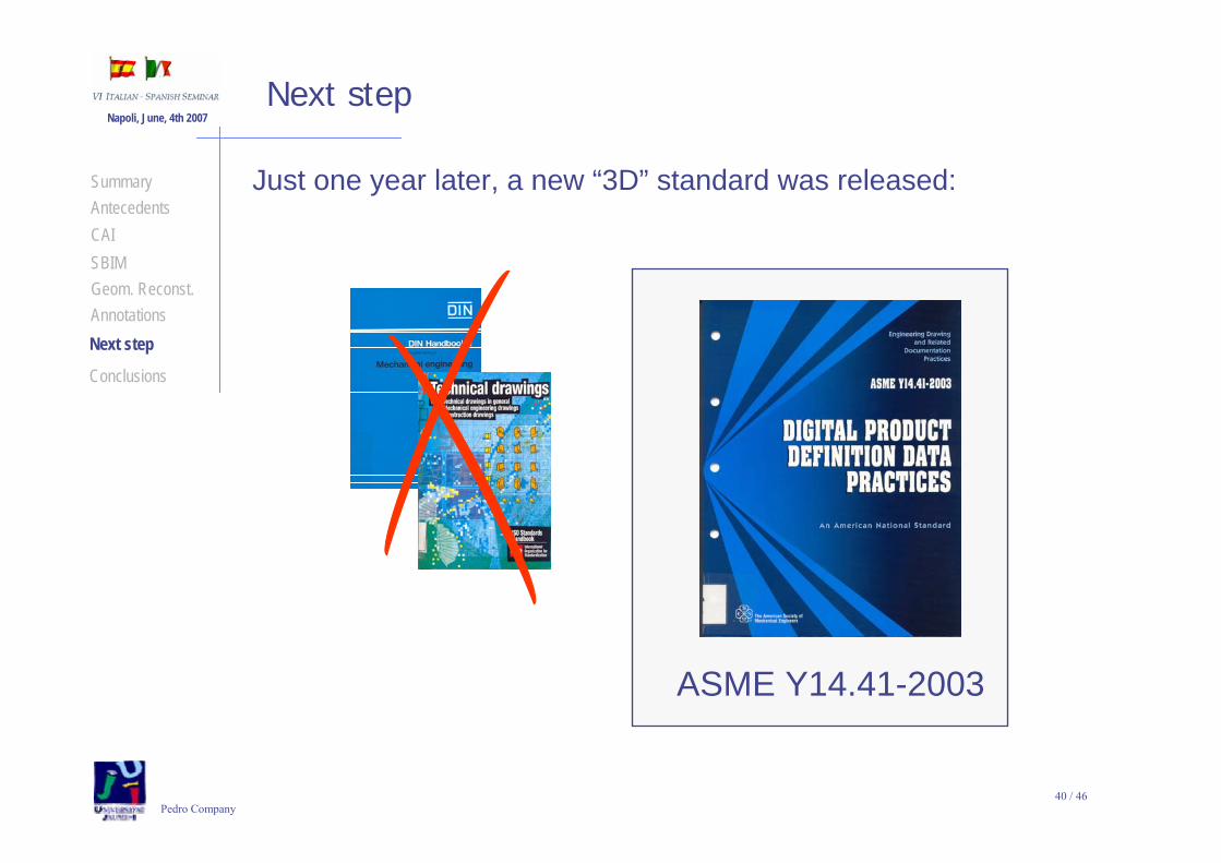
ASME Y14.41-2003
Next step
Just one year later, a new “3D” standard was released:
CAISBIMGeom. Reconst.AnnotationsNext step
AntecedentsSummary
Conclusions

41 / 46Pedro Company
Napoli, June, 4th 2007Next step
the model may contain the following information:
Annotation
MODEL
Design model
Attributes
Model geometry
Supplemental geometry
Geometric elements
According to ASME Y14.41-2003,CAISBIMGeom. Reconst.AnnotationsNext step
AntecedentsSummary
Conclusions
Annotationscan be includedin the models!

42 / 46Pedro Company
Napoli, June, 4th 2007Next step
than the user can read and modify,
Annotation
MODEL
Design model
Attributes
Model geometry
Supplemental geometry
Geometric elements
But the computer is blind to those annotations!
The annotations are just “labels” added to the model
but the geometrical engine does not use them,neither to construct, nor to edit or validate the model.
CAISBIMGeom. Reconst.AnnotationsNext step
AntecedentsSummary
Conclusions

43 / 46Pedro Company
Napoli, June, 4th 2007
Manufacturing Engineers
Conclusions
Designers
Computer graphics technologists
All of them are required to face this challenging
problem
CAISBIMGeom. Reconst.AnnotationsNext step
AntecedentsSummary
Conclusions

44 / 46Pedro Company
Napoli, June, 4th 2007 Tools for easing theTools for easing theHumanHuman--Computer InteractionComputer Interaction
during Virtual Assembly Process,during Virtual Assembly Process,by way of Sketchby way of Sketch--Based InterfacesBased Interfaces
Pedro Company

45 / 46Pedro Company
Napoli, June, 4th 2007
46 / 46Pedro Company
Napoli, June, 4th 2007