1 2 An 18680 dwt Multipurpose/ Radojka RIMANIĆ 2 Heavy ... Grubisic.pdf · AN 18680 DWT...
16
157 60(2009)2, 157-162 UDC 629.5:338.3629.542.2:629.5.065.2 Rajko GRUBIŠIĆ 1 Robert GRUBIŠA 2 Radojka RIMANIĆ 2 Radivoj VLAH 2 Edi KUČAN 2 Miroslav ŠTOKIĆ 2 An 18680 dwt Multipurpose/ Heavy Lift Cargo Vessel, Part II Professional paper In the article the second part of the significant design features of an 18680 dwt multipurpose/ heavy lift cargo vessel is presented. The specific features of the ship structure design are first dealt with. Then, the propulsion assembly, including the main engine, the gearbox/coupling and the controllable pitch propeller system, is described. Also, features of the electrical system are given, with special emphasis laid on the supply, driving and controlling system of the heavy cargo deck cranes. Finally, the 3D finite element modelling of the engine room is described, pointing out the advantages of such a design technique. Keywords: deck cranes, design features, propulsion systems Višenamjenski brod za dizanje teških tereta nosivosti 18680 dwt, II. dio Stručni rad U članku je prikazan drugi dio značajki projekta višenamjenskog broda za prijevoz teških tereta nosivosti 18680 dwt. Prvo su opisane značajke projekta brodske strukture. Zatim je prikazan pogonski sklop uključujući glavni stroj, reduktor/spojku i sustav vijka s promjenjivim usponom. Također, dane su značajke sustava električne energije, s posebnim naglaskom na sustav napajanja, pogona i upravljanja palubnih dizalica za teške terete. Konačno, opisano je 3D modeliranje brodske strojarnice s konačnim elementima, s isticanjem prednosti ovakve tehnike projektiranja. Ključne riječi: palubne dizalice, projektne značajke, pogonski sustavi Authors’ addresses: 1 Faculty of Mechanical Engineering and Naval Architecture, University of Zagreb, I. Lučića 5, 10000 Zagreb E-mail: [email protected] 2 3. maj, Liburnijska 3, 51000 Rijeka Received (Primljeno): 2009-03-26 Accepted (Prihvaćeno): 2009-04-17 Open for discussion (Otvoreno za raspravu): 2010-06-30 1 Instead of an introduction In the preceding issue of the journal, the first part of the heavy lift cargo vessel design was presented, where specific contract particulars, ship design features, heavy cargo loading cases and ship damage stability were described. In this issue, the other part of this design, including the ship structure, propulsion assembly, electricity system and the engine room modelling, will be presented. 2 Ship structure The preparation of the ship structure classification drawings was contracted with the ship design office Navtec Marine of Rijeka. As the main input for the structure design a 3D model from 3. maj was used, where most spaces and a part of the main equipment were added. Also, Navtec Marine designers added specific cargo securing equipment structure reinforcements to the structure drawings i.e. Technical Specification, in accordance with the requirements from the Owner. 2D drawings in DGN-format were taken over and examined by the shipyard 3. maj. Then, they were delivered in PDF-format to the client BigLift for approval. After being approved by BigLift, and corrected by Navtec Ma- rine where necessary, the documentation was forwarded to the LR EMEA office in Rotterdam for a final approval. In addition, in accordance with the BigLift request, at a very early stage of the structure design, Navtec Marine started with a complete cargo zone FEM modelling in order to prepare the FEM analysis before the final delivery of the drawings. The LR EMEA office has de- livered the approved drawings together with the design appraisal document in PDF-format to the shipyard 3. maj. Thus, the entire preparation/acceptance/examination/approval procedure of the hull structure classification documentation was accomplished by using only electronic means of communica- tion. 2.1 Specific features of the ship structure design Here, some essential features related to the ship structure are presented. Class notation Lloyd’s Register of Shipping for the class: 100 A1 Ice class 1A (Finish) “Strengthened for Heavy Cargoes”, “Timber Deck Cargoes”, “Container Cargoes in Hold on Deck and on Upper Deck Hatch Covers”, LA, +LMC, UMS, IWS, PCWBT, SCM, NAV1. Hull longitudinal strength The longitudinal strength of the hull structure elements is defined according to the greater value either of the maximum still water bending moment for all loading cases with a 10 % increase or of the permissible still water bending moment according to the classification rules with a 10 % increase. For illustration, the latter moment makes:
Transcript of 1 2 An 18680 dwt Multipurpose/ Radojka RIMANIĆ 2 Heavy ... Grubisic.pdf · AN 18680 DWT...
15760(2009)2, 157-162
AN 18680 DWT MULTIPURPOSE... R. GRUBIŠIĆ, R. GRUBIŠA, R. RIMANIĆ, R. VLAH, E. KUČAN, M. ŠTOKIĆUDC 629.5:338.3629.542.2:629.5.065.2
Rajko GRUBIŠIĆ 1
Robert GRUBIŠA 2
Radojka RIMANIĆ 2
Radivoj VLAH 2
Edi KUČAN 2
Miroslav ŠTOKIĆ 2
An 18680 dwt Multipurpose/Heavy Lift Cargo Vessel, Part II
Professional paper
In the article the second part of the signifi cant design features of an 18680 dwt multipurpose/heavy lift cargo vessel is presented. The specifi c features of the ship structure design are fi rst dealt with. Then, the propulsion assembly, including the main engine, the gearbox/coupling and the controllable pitch propeller system, is described. Also, features of the electrical system are given, with special emphasis laid on the supply, driving and controlling system of the heavy cargo deck cranes. Finally, the 3D fi nite element modelling of the engine room is described, pointing out the advantages of such a design technique.
Keywords: deck cranes, design features, propulsion systems
Višenamjenski brod za dizanje teških tereta nosivosti 18680 dwt, II. dio
Stručni rad
U članku je prikazan drugi dio značajki projekta višenamjenskog broda za prijevoz teških tereta nosivosti 18680 dwt. Prvo su opisane značajke projekta brodske strukture. Zatim je prikazan pogonski sklop uključujući glavni stroj, reduktor/spojku i sustav vijka s promjenjivim usponom. Također, dane su značajke sustava električne energije, s posebnim naglaskom na sustav napajanja, pogona i upravljanja palubnih dizalica za teške terete. Konačno, opisano je 3D modeliranje brodske strojarnice s konačnim elementima, s isticanjem prednosti ovakve tehnike projektiranja.
Ključne riječi: palubne dizalice, projektne značajke, pogonski sustavi
Authors’ addresses:1 Faculty of Mechanical Engineering
and Naval Architecture, University of
Zagreb,
I. Lučića 5, 10000 Zagreb
E-mail: [email protected] 3. maj, Liburnijska 3, 51000 Rijeka
Received (Primljeno): 2009-03-26
Accepted (Prihvaćeno): 2009-04-17
Open for discussion (Otvoreno za
raspravu): 2010-06-30
1 Instead of an introduction
In the preceding issue of the journal, the fi rst part of the heavy lift cargo vessel design was presented, where specifi c contract particulars, ship design features, heavy cargo loading cases and ship damage stability were described.
In this issue, the other part of this design, including the ship structure, propulsion assembly, electricity system and the engine room modelling, will be presented.
2 Ship structure
The preparation of the ship structure classifi cation drawings was contracted with the ship design offi ce Navtec Marine of Rijeka. As the main input for the structure design a 3D model from 3. maj was used, where most spaces and a part of the main equipment were added. Also, Navtec Marine designers added specifi c cargo securing equipment structure reinforcements to the structure drawings i.e. Technical Specifi cation, in accordance with the requirements from the Owner. 2D drawings in DGN-format were taken over and examined by the shipyard 3. maj. Then, they were delivered in PDF-format to the client BigLift for approval. After being approved by BigLift, and corrected by Navtec Ma-rine where necessary, the documentation was forwarded to the LR EMEA offi ce in Rotterdam for a fi nal approval. In addition, in accordance with the BigLift request, at a very early stage of the structure design, Navtec Marine started with a complete cargo zone FEM modelling in order to prepare the FEM analysis before
the fi nal delivery of the drawings. The LR EMEA offi ce has de-livered the approved drawings together with the design appraisal document in PDF-format to the shipyard 3. maj.
Thus, the entire preparation/acceptance/examination/approval procedure of the hull structure classifi cation documentation was accomplished by using only electronic means of communica-tion.
2.1 Specifi c features of the ship structure design
Here, some essential features related to the ship structure are presented.
Class notation
Lloyd’s Register of Shipping for the class: 100 A1 Ice class 1A (Finish) “Strengthened for Heavy Cargoes”, “Timber Deck Cargoes”, “Container Cargoes in Hold on Deck and on Upper Deck Hatch Covers”, LA, +LMC, UMS, IWS, PCWBT, SCM, NAV1.
Hull longitudinal strength
The longitudinal strength of the hull structure elements is defi ned according to the greater value either of the maximum still water bending moment for all loading cases with a 10 % increase or of the permissible still water bending moment according to the classifi cation rules with a 10 % increase. For illustration, the latter moment makes:
158 60(2009)2, 157-162
R. GRUBIŠIĆ, R. GRUBIŠA, R. RIMANIĆ, R. VLAH, E. KUČAN, M. ŠTOKIĆ AN 18680 DWT MULTIPURPOSE...
• MB hog
= 753 400 kNm
• MB sag
= -672 000 kNm
Increase in plating thickness
The client Biglift, in accordance with the building experi-ences with preceding ships of the same purpose, required the increase in the plating thickness beyond the classifi cation rules for the following parts:
• hull shell plating for 5 mm in the marine propeller area• lower part of the bulkhead for 2 mm in the hold• double bottom top plating for 2 mm.
Heavy lift deck cranes
Two deck cranes, each heaving a 900 t lifting capacity, are installed on the ship starboard side. During the structure design, Navtec Marine proposed to Huisman the solution of the basic structure within the crane double side areas and, after some co-ordination activities, Huisman and Navtec Marine agreed about the best structural and equipment arrangement. Both cranes and the double side structure below them will be delivered by the crane manufacturer Huisman.
Non-symmetry of the hull structure
The position of the cranes on the ship starboard side stipulates certain non-symmetry of the hull structure with respect to the longitudinal symmetry plane. In the cargo hold the breadth of the starboard double side is 4800 mm and that of the port double
side is 3980 mm. On the fore part with the superstructure, the half breadth of the superstructure lower part with the crew ac-commodations is 8000 mm on the starboard side and 8800 mm on the port side.
Mobile pontoon tweendeck covers and mobile transverse bulkhead
The supports for the pontoon covers, as a part of the double side structure in cargo holds, enable various positions in the height of the tweendeck pontoon covers.
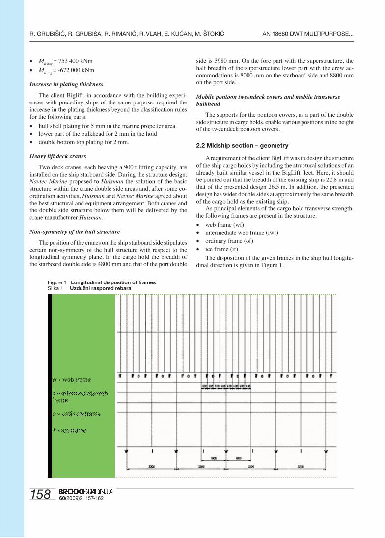
2.2 Midship section – geometry
A requirement of the client BigLift was to design the structure of the ship cargo holds by including the structural solutions of an already built similar vessel in the BigLift fl eet. Here, it should be pointed out that the breadth of the existing ship is 22.8 m and that of the presented design 26.5 m. In addition, the presented design has wider double sides at approximately the same breadth of the cargo hold as the existing ship.
As principal elements of the cargo hold transverse strength, the following frames are present in the structure:
• web frame (wf)• intermediate web frame (iwf)• ordinary frame (of)• ice frame (if)
The disposition of the given frames in the ship hull longitu-dinal direction is given in Figure 1.
Figure 1 Longitudinal disposition of framesSlika 1 Uzdužni raspored rebara
15960(2009)2, 157-162
AN 18680 DWT MULTIPURPOSE... R. GRUBIŠIĆ, R. GRUBIŠA, R. RIMANIĆ, R. VLAH, E. KUČAN, M. ŠTOKIĆ
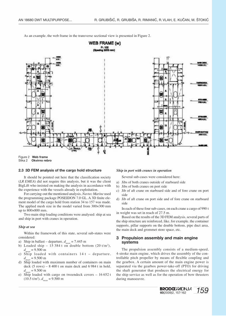
As an example, the web frame in the transverse sectional view is presented in Figure 2.
Ship in port with cranes in operation
Several sub-cases were considered here:
a) Jibs of both cranes outside of starboard sideb) Jibs of both cranes on port sidec) Jib of aft crane on starboard side and of fore crane on port
sided) Jib of aft crane on port side and of fore crane on starboard
side
In each of these four sub-cases, on each crane a cargo of 990 t in weight was set in reach of 27.5 m.
Based on the results of the 3D FEM analysis, several parts of the ship structure are reinforced, like, for example, the container supports, pillar supports on the double bottom, pipe duct area, the main deck and grommet store space, etc.
3 Propulsion assembly and main engine systems
The propulsion assembly consists of a medium-speed, 4-stroke main engine, which drives the assembly of the con-trollable pitch propeller by means of fl exible coupling and the gearbox. A certain amount of the main engine power is separated via the gearbox power-take-off (PTO) for driving the shaft generator that produces the electrical energy for the ship service as well as for the operation of bow thrusters during manoeuvre.
Figure 2 Web frameSlika 2 Okvirno rebro
2.3 3D FEM analysis of the cargo hold structure
It should be pointed out here that the classifi cation society (LR EMEA) did not require this analysis, but it was the client BigLift who insisted on making the analysis in accordance with the experience with the vessels already in exploitation.
For carrying-out the mentioned analysis, Navtec Marine used the programming package POSEIDON 7.0 GL. A 3D fi nite ele-ment model of the cargo hold from station 34 to 157 was made. The applied mesh size in the model varied from 300×300 mm up to 800×800 mm.
Two main ship loading conditions were analysed: ship at sea and ship in port with cranes in operation.
Ship at sea
Within the framework of this state, several sub-states were considered:a) Ship in ballast – departure, d
mean = 7.445 m
b) Loaded ship – 15 384 t on double bottom (20 t/m2), d
mean = 9.500 m
c) Ship loaded wi th conta iners 14 t – depar ture , d
mean = 9.500 m
d) Ship loaded with maximum number of containers on main deck (5 rows) – 8 400 t on main deck and 6 984 t in hold, d
mean = 9.500 m
e) Ship loaded with cargo on tweendeck covers – 16 652 t (10.5 t/m2), d
mean = 9.500 m
160 60(2009)2, 157-162
R. GRUBIŠIĆ, R. GRUBIŠA, R. RIMANIĆ, R. VLAH, E. KUČAN, M. ŠTOKIĆ AN 18680 DWT MULTIPURPOSE...
3.1 Main engine
The characteristics of the main engine are as follows:• Power: 8775 kW• Revolution number: 500 min-1
• Fuel: HFO, viscosity 380 cSt/50°C, maximum density 1010 kg/m3 at 15°CThe following three main engine manufacturers were con-
sidered:• Wärtsilä, type 9/8L46, power 8775/7800 kW at 500 min-1
• MaK, type 9/M43 C, power 9000 kW at 500 min-1
• MAN, type 8L48/60B, power 9600 kW at 500 min-1
All three engines satisfi ed the given technical conditions, but, in the contact with the manufacturer, attempts to achieve the same delivery range, such as the same volume of the associated equip-ment, attendance systems, etc., were made. A very important (if not the most important one) condition was the fuel consumption, which at 85% MCR ranged from 175 g/kWh to 178 g/kWh with a 5 % tolerance.
Due to the fact that the decision about the fi nal choice of the main engine was on the client’s side, a preliminary ER ar-rangement for each of the given main engines was made in the design phase. In the later phase of the design development, the client decided in favour of the WÄRTSILÄ 8L46 main engine, with the power of 8775 kW at 500 min-1. Therefore, the detailed documentation was made in accordance with the manufacturer’s recommendations.
3.2 Gearbox/coupling
For the propulsion assembly, a single reduction gear box with vertical motion and with PTO connection for the shaft generator will be installed. The gearbox arrangement includes the built-in thrust bearing as well as the cooling and lubricating system. The main engine/propeller transmission ratio is 500/140, and the gear box/PTO transmission ratio is 500/1800.
Three kinds of gearboxes were considered: Reintjes, type SVA 1200A, Renk RSV-1120 and Renk RSV-1060. The client decided to choose Renk RSV-1060, so that, after defi ning the fi nal dimen-sions, the gear box and the fl exible coupling were fi tted into the
propulsion assembly arrangement. The main engine manufacturer will deliver the fl exible coupling, whose fi nal characteristics depend on the torsional vibration analysis.
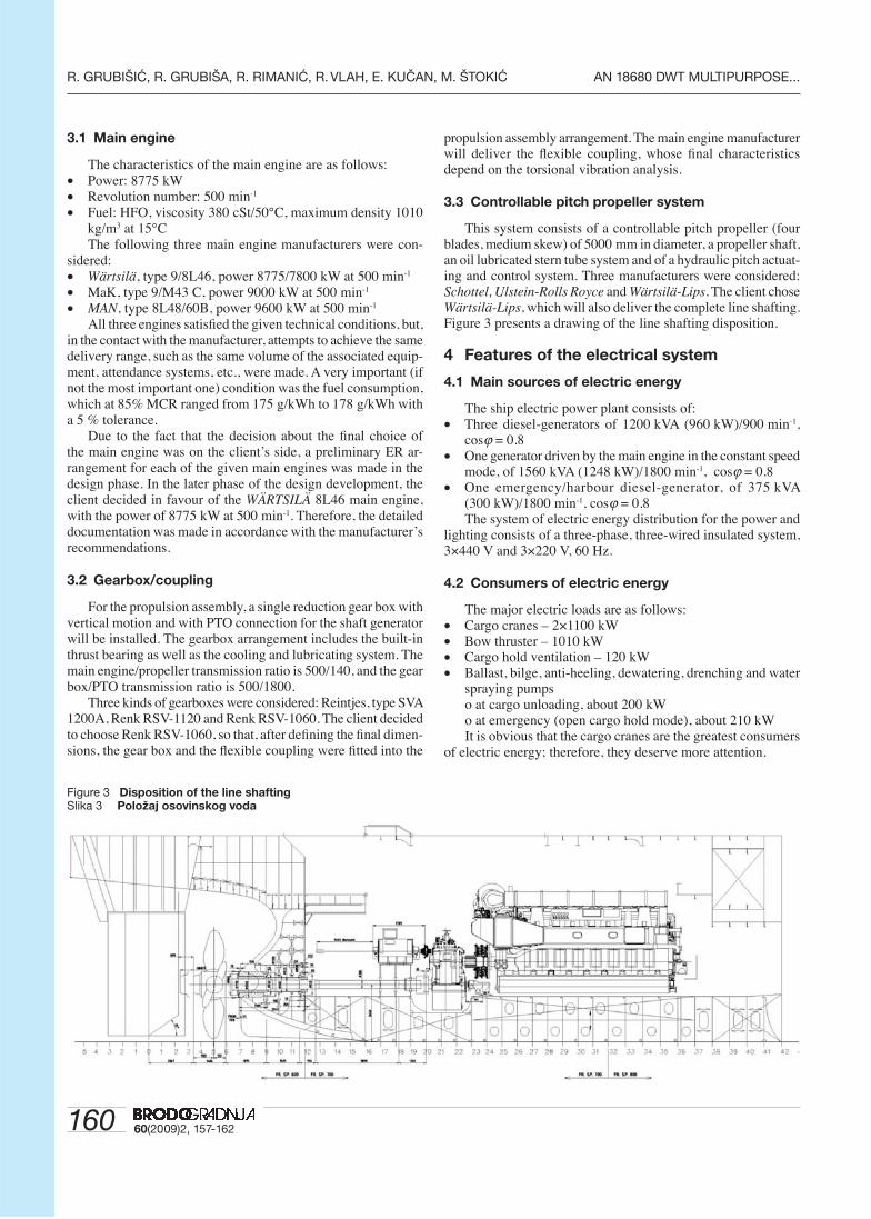
3.3 Controllable pitch propeller system
This system consists of a controllable pitch propeller (four blades, medium skew) of 5000 mm in diameter, a propeller shaft, an oil lubricated stern tube system and of a hydraulic pitch actuat-ing and control system. Three manufacturers were considered: Schottel, Ulstein-Rolls Royce and Wärtsilä-Lips. The client chose Wärtsilä-Lips, which will also deliver the complete line shafting. Figure 3 presents a drawing of the line shafting disposition.
4 Features of the electrical system
4.1 Main sources of electric energy
The ship electric power plant consists of: • Three diesel-generators of 1200 kVA (960 kW)/900 min-1,
cosϕ = 0.8 • One generator driven by the main engine in the constant speed
mode, of 1560 kVA (1248 kW)/1800 min-1, cosϕ = 0.8• One emergency/harbour diesel-generator, of 375 kVA
(300 kW)/1800 min-1, cosϕ = 0.8 The system of electric energy distribution for the power and
lighting consists of a three-phase, three-wired insulated system, 3×440 V and 3×220 V, 60 Hz.
4.2 Consumers of electric energy
The major electric loads are as follows:• Cargo cranes – 2×1100 kW• Bow thruster – 1010 kW• Cargo hold ventilation – 120 kW• Ballast, bilge, anti-heeling, dewatering, drenching and water
spraying pumpso at cargo unloading, about 200 kWo at emergency (open cargo hold mode), about 210 kWIt is obvious that the cargo cranes are the greatest consumers
of electric energy; therefore, they deserve more attention.
Figure 3 Disposition of the line shaftingSlika 3 Položaj osovinskog voda
16160(2009)2, 157-162
AN 18680 DWT MULTIPURPOSE... R. GRUBIŠIĆ, R. GRUBIŠA, R. RIMANIĆ, R. VLAH, E. KUČAN, M. ŠTOKIĆ
4.3 Heavy lift cranes
Main characteristics
Crane type: Huisman Heavy Lift Mast Crane (HLMC) hav-ing Safe Working Load 900 t at 27.5 m radius or 600 t at 33 m radius.
Driving system
The cranes have a redundant electric AC drive system with static frequency converters without the use of any hydraulics. Deceleration occurs by means of electric braking (“0” speed control). All drives have two brakes each.
Drive motors
Main hoist 2×300 kWLuffi ng 200 kWAuxiliary hoist 200 kWTrolley travel 100 kWSlewing 6×60 kWTugger 2×54 kWSling hoist 54 kW
Electric power production
The ship supply 2×440 V, 60 Hz, 1250 kVA is transformed to 12-pulse 690 V by means of a transformer having one primary and two secondary parts, i.e. 6 phases with a 30° shift for reducing the harmonic distortion. Each crane has its own rectifi er system and static inverters for a stepless control of the driving speed. The generators should accomplish the maximum driving power within 4 s; otherwise the drives operate with a lower acceleration than the nominal one.
Auxiliary supply: about 100 kVAEmergency supply: about 20 kVA
Inverter system
The inverters of individual drives are supplied from common DC bus. The fl ux vector controlled AC motors are fi tted with pulse generators for a precise speed and moment control. The control range is 1:1000 for the speed and 1:100 for the moment.
Total installed power: 1820 kWMaximum simultaneous power consumption of one crane: 1100 kWMaximum simultaneous power consumption of both cranes: 1600 kW
Control and supervision of cranes
The cranes are controlled by means of programmable logic controllers in the control cabinet of each crane. The remote control is achieved by means of portable wireless control/supervision units having docking stations and LCD displays in the wheelhouse.
5 3D modelling of the engine room
When designing the 3D model of the ship engine room, it was necessary to satisfy the following conditions:• The forward bulkhead limited by the cargo hold for placing
14 bays of TEU containers
• The breadth of the engine room determined by a relatively fi ne stern form
• The maximum height of the engine room (9.3 m from the double bottom up to the main deck) is limited above the engine room for the CO
2, emergency diesel generator and stern fans
accomodation• The arrangement of the engine equipment on two engine room
platforms and on the engine room fl oor limited due to a very low room height
• The dimensions of the engine room hatch and the funnel, placed on the ship port side, were limited because of the necessary area for manipulation and placement of heavy cargo from the ship stern towards the stem
• The placement of one part of the tweendeck covers on the stern position in the engine room recess
• The requirement of a "box shape" cargo hold, so that the stern ventilation ducts as well as the way down into the hold are made on account of one part of the engine room space
• A greater number of fuel and lubrication oil tanks in the engine room than in ordinary ships
• The position of the ventilation ducts for the engine room ventilation system through the stern cargo crane body and the side passage
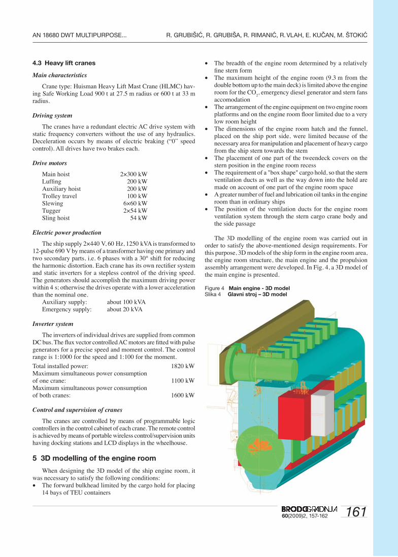
The 3D modelling of the engine room was carried out in order to satisfy the above-mentioned design requirements. For this purpose, 3D models of the ship form in the engine room area, the engine room structure, the main engine and the propulsion assembly arrangement were developed. In Fig. 4, a 3D model of the main engine is presented.
Figure 4 Main engine - 3D modelSlika 4 Glavni stroj – 3D model
162 60(2009)2, 157-162
R. GRUBIŠIĆ, R. GRUBIŠA, R. RIMANIĆ, R. VLAH, E. KUČAN, M. ŠTOKIĆ AN 18680 DWT MULTIPURPOSE...
The 3D modelling of the engine room in the initial design phase enables to the designer a quicker recognition of all critical positions in the space of the ship engine room.
A 3D design model enables the time reduction when mak-ing the technical documentation for the engine room outfi tting because, after the hull classifi cation documentation is made, the developing of the fi nal 3D engine room arrangement model can start without having to wait for the completion of the hull workshop documentation.
In particular, the checking of the 3D design model versus the 2D hull drawings is very important and useful.
6 Summary
The most signifi cant design features of a 18680 dwt multi-purpose/heavy lift cargo vessel are presented in two issues of this journal. The presented design was completely developed by the designers of the shipyard 3. maj in Rijeka and was introduced for the fi rst time to the experts in the fi eld at the annual meeting of the Croatian ship designers held in Rijeka. On that occasion it was decided to publish it in the journal Brodogradnja.
In the fi rst part, the contract particulars are described, with a special focus given to the cooperation of the designers and the client in making the choice of the propulsion assembly items, and also to the agreement that the crane manufacturer will de-liver not only the cranes but will also provide the hull structure underneath them. Then, the basic ship concept with a list of requirements and classifi cation/regulation rules is given. Here, the ship stability calculation in the survival condition for “open ship”, in accordance with additional stability criteria, is pointed out. Results of the stability analysis for 5 heavy cargo loading cases are presented, showing that in all cases the client’s and the USCG requirements are fulfi lled. Finally, the subdivision
and damage stability analysis (probability method) is described. Results for three navigation cases, with and without removable bulkhead in hold and with open hatch openings on the main deck, are given, showing that the attained subdivision index in all three cases satisfi es the required subdivision index.
In the second part, the specifi c features of the ship structure design are fi rst dealt with. The following issues are discussed: the increase in plating thickness beyond the classifi cation rules of the hull shell in the propeller area, of the lower bulkhead part in the hold and of the double bottom top; the non-symmetry of the hull structure due to the starboard position of the heavy lift deck cranes; mobile pontoon tweendeck covers and mobile transverse bulkhead; various structural web and ordinary frames as trans-verse strength elements in the cargo hold area; and, fi nally, the 3D FEM analysis of the hold structure for two main ship states, is presented. Then, the propulsion assembly, including the main engine, the gearbox/coupling and the controllable pitch propel-ler system, is described. Also, features of the electrical system, such as main electric energy sources and consumers, are given, with special emphasis laid on the supply, driving and controlling system of heavy cargo deck cranes as the main electric energy consumers. Finally, the 3D fi nite element modelling of the engine room is described. The advantages of such a design technique, such as the adjustment to the ship form, the appropriate disposi-tion of the fi ttings and of other equipment and the early recogni-tion of critical position, are pointed out.
Aknowledgement
Here again, like at the end of Part I, we would like to express our gratitude to all members of the 3. maj design offi ce. Their contributions and the excellent cooperation with the journal’s editorial offi ce have created this article.

16360(2009)2, 157-162
AN 18680 DWT MULTIPURPOSE... R. GRUBIŠIĆ, R. GRUBIŠA, R. RIMANIĆ, R. VLAH, E. KUČAN, M. ŠTOKIĆ


AXIS
-DES
IGN
2008
The KRALJEVICA Shipyard ranks, in view of its capacities, among medium-sized shipyards (500 employees, area of 110,000 m2).
The KRALJEVICA Shipyard’s activities are divided in three main groups:newbuildings (asphalt tankers, multipurpose vessels, container vessels,dry cargo vessels, paper carriers, RO-RO vessels, car ferries, offshoresupply vessels, tugs, yachts, fishing vessels, small aluminum crafts,etc.), navy vessels (patrol vessels, corvettes, coast guard vessels, etc.),shiprepairing/retrofitting (merchant and navy vessels).
As from the end of Second World War, the Shipyard built more than 180 vessels of which 80 navy vessels and more than 100 merchantvessels on two open slipways of up to 10,000 tdw (125 x 21 m) and one sheltered slipway in hall (for vessels up to 60 x 11 m).
Shiprepairing and marine service-conversions for vessels up to 25,000tdw in two floating docks of 450 tons and 6,500 tons lifting capacity(for vessels of maximum 155 x 21 m), and on shiprepairing quay of 575meters in length.
The Shipyard have awarded for his quality two prestigious prizes:• in Year 1989 for RO-RO/Container/paper carrier of 3,400 tdw
as one of the Most Outstanding Ship of the Year(by US magazine “Maritime Reporter & Engineering News”)
• in Year 2005 for Asphalt carrier of 9,200 tdw as one of the Significant Ship of the Year(by UK magazine “The Naval Architect”)
KRALJEVICA SHIPYARDSHIPBUILDING SINCE 1729
The KRALJEVICA Shipyard, shipbuilding and shiprepairing company, is the oldestshipyard on the eastern coast of the Adriatic Sea. The continuity of shipbuilding in KRALJEVICA has been lasting uninterrupted since1729, when the Shipyard has been established by the Austrian Emperor Karl VI.
KRALJEVICA ShipyardObala Kralja Tomislava 8, P.O.Box 35, 51262 Kraljevica, CroatiaSales Department Tel.: +385 (51) 416 278 Fax: +385 (51) 416 405e-mail: [email protected] www.brodkr.hr

AXIS
-DES
IGN
2008
SHIPYARD TROGIRPut brodograditelja 1621220 TROGIR - CROATIAPhone: +385 21 /883 333 (Switchboard)+385 21 /883 201 (Sales Department)Fax:+385 21 /881 881 (Central)+385 21 /883 417 (Sales Department)e-mail: [email protected]
SHIPREPAIR DIVISIONPut brodograditelja 1621220 TROGIR - CROATIA
Phone: +385 21 /883 303 Fax: +385 21 /883 406E-mail: [email protected]
www.brodotrogir.hr
S H I P Y A R D T R O G I R
Tradition Quality Inovation